Page 3434 of 5135

76±31
AVENSIS REPAIR MANUAL (RM1018E)
(2) Remove the tape from the back door.
(3) Wipe off the stains with cleaner.
(b")
B67164
Double±sided Tape
± EXTERIOR/INTERIOR TRIMREAR SPOILER (WAGON MODELS)
76±31
AVENSIS REPAIR MANUAL (RM1018E)
(2) Remove the tape from the back door.
(3) Wipe off the stains with cleaner.
(b) When reusing the spoiler:
Clean the spoiler.
(1) Using a heat light, heat the spoiler.
Heating temprature: 20 ± 30�C (68 ± 86�F)
NOTICE:
Do not heat the spoiler excessively.
(2) Remove the tape from the spoiler.
(3) Wipe off the stains with cleaner.
(c) Install the spoiler.
(1) Using a heat light, heat the door and spoiler.
Heating temperature:
Door40 ± 60�C (104 ± 140�F)
Spoiler20 ± 30�C (68 ± 86�F)
NOTICE:
Do not heat the door and spoiler excessively.
(2) Apply new double±sided tape to the spoiler, as
shown in the illustration.
(3) Remove the peeling paper from the spoiler.
NOTICE:
Be careful that dirt or foreign objects do not stick to the
adhesive part when removing the peeling paper.
(4) Install the spoiler with the 6 nuts.
Torque: 9.8 N�m (99 kgf�cm, 87 in.�lbf)
NOTICE:
Do not apply excessive force onto the spoiler. Instead, ap-
ply steady pressure with your thumbs.
(5) Connect the stop lamp connector.
(6) Install the 4 hole plugs.
Page 3457 of 5135
031FL±01
± SERVICE SPECIFICATIONSLUBRICATION
03±9
1AZ±FSE ENGINE REPAIR MANUAL (RM1019E)
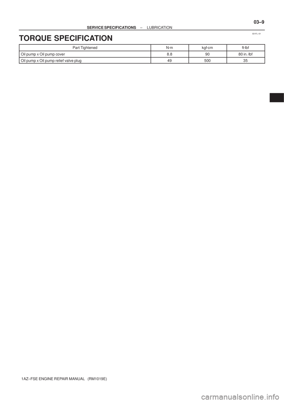
TORQUE SPECIFICATION
Part TightenedN�mkgf�cmft�lbf
Oil pump x Oil pump cover8.89080 in.�lbf
Oil pump x Oil pump relief valve plug4950035
Page 3467 of 5135
141BV±01
A77366
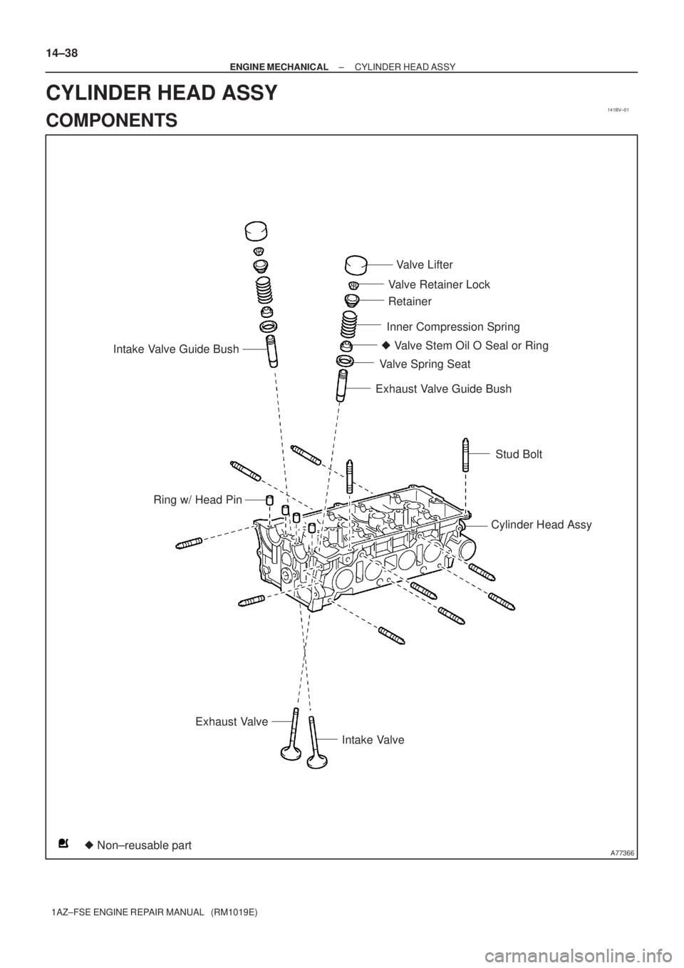
Intake Valve Guide Bush
� Non±reusable part� Valve Stem Oil O Seal or RingValve Lifter
Valve Retainer Lock
Retainer
Inner Compression Spring
Valve Spring Seat
Exhaust Valve Guide Bush
Stud Bolt
Cylinder Head Assy
Intake Valve Exhaust Valve Ring w/ Head Pin
14±38
± ENGINE MECHANICALCYLINDER HEAD ASSY
1AZ±FSE ENGINE REPAIR MANUAL (RM1019E)
CYLINDER HEAD ASSY
COMPONENTS
Page 3469 of 5135
A79722
A82638
A82639
A82640
A82641
Terminal C
Terminal 50Continuity
± STARTING & CHARGINGSTARTER ASSY
19±3
1AZ±FSE ENGINE REPAIR MANUAL (RM1019E)
4. REMOVE STARTER ARMATURE PLATE
(a) Remove the armature plate from the starter yoke.
5. REMOVE STARTER BRUSH HOLDER ASSY
(a) Remove the 2 screws and brush holder assy from the
commutator end frame.
6. REMOVE PLANET GEAR
(a) Remove the 3 planet gears from the repair service starter
kit.
7. INSPECT REPAIR SERVICE STARTER KIT
(a) Check the plunger.
(1) Push in the plunger and check that it returns quickly
to its original position.
If necessary, replace the repair service starter kit.
(b) Check the pull±in coil for open circuit.
(1) Using an ohmmeter, check that there is continuity
between terminals 50 and C.
If there is no continuity, replace the repair service starter kit.
Page 3470 of 5135

(c) Check if the hold±in coil")
A82642
Terminal 50Continuity
A82643
Continuity
A82644No Continuity
A82645
A82646
29mm 19±4
± STARTING & CHARGINGSTARTER ASSY
1AZ±FSE ENGINE REPAIR MANUAL (RM1019E)
(c) Check if the hold±in coil has an open circuit.
(1) Using an ohmmeter, check that there is continuity
between terminal 50 and the switch body.
If there is no continuity, replace the repair service kit.
8. INSPECT STARTER ARMATURE ASSY
(a) Check the commutator for open circuit.
(1) Using an ohmmeter, check that there is continuity
between the segments of the commutator.
If there is no continuity between any segments, replace the ar-
mature.
(b) Check the commutator for ground.
(1) Using an ohmmeter, check that there is no continu-
ity between the commutator and the armature coil
core.
If there is continuity, replace the armature.
(c) Check the commutator for dirty or burned surface.
If the surface is dirty or burnt, smooth the surface with 400±grit
sandpaper.
(d) Check for the commutator circuit runout.
(1) Place the commutator on V±blocks.
(2) Using a dial indicator, measure the circle runout.
Standard runout: 0.02 mm (0.0008 in.)
Maximum runout: 0.05 mm (0.0020 in.)
If the runout is greater than maximum, replace the armature.
(e) Using vernier calipers, measure the commutator diame-
ter.
Standard length: 29 mm (1.142 in.)
Minimum length: 28 mm (1.102 in.)
If the diameter is less than minimum, replace the armature.
Page 3474 of 5135

OVERHAUL
1. REMOVE OIL PUMP RELIEF VALVE PLUG
(a) Using a 27 mm socket wrench, re")
170FM±01
A77229
A77233
A77230
Mark
A77231
17±2
± LUBRICATIONOIL PUMP ASSY
1AZ±FSE ENGINE REPAIR MANUAL (RM1019E)
OVERHAUL
1. REMOVE OIL PUMP RELIEF VALVE PLUG
(a) Using a 27 mm socket wrench, remove the oil pump relief plug.
SST 09011±12271
2. REMOVE OIL PUMP RELIEF VALVE SPRING
3. REMOVE OIL PUMP RELIEF VALVE
4. INSPECT OIL PUMP RELIEF VALVE
(a) Coat the oil pump relief valve with engine oil.
(b) Check that it falls smoothly into the oil pump relief valve
hole by its own weight.
If it does not, replace the oil pump relief valve.
If necessary, replace the oil pump assembly.
5. REMOVE OIL PUMP COVER
(a) Remove 7 bolts and the oil pump cover.
6. INSPECT OIL PUMP ROTOR SET
(a) Place the drive and driven rotors into the oil pump body
with the marks facing the oil pump cover.
7. INSPECT ROTOR TIP CLEARANCE
(a) Using a feeler gauge, measure the clearance between
the drive and driven rotor tip.
Standard tip clearance:
0.080 to 0.160 mm (0.0031 to 0.0063 in.)
Maximum tip clearance: 0.35 mm (0.0138 in.)
If the tip clearance is greater than maximum, replace the rotors
as a set.
Page 3475 of 5135

8. INSPECT ROTOR BODY CLEARANCE
(a) Using a feeler gauge, measure the clearance between
the drive")
A77232
A38022
A77234
Marks
± LUBRICATIONOIL PUMP ASSY
17±3
1AZ±FSE ENGINE REPAIR MANUAL (RM1019E)
8. INSPECT ROTOR BODY CLEARANCE
(a) Using a feeler gauge, measure the clearance between
the driven rotor and body.
Standard body clearance:
0.100 to 0.170 mm (0.0039 to 0.067 in.)
Maximum body clearance: 0.325 mm (0.0128 in.)
If the body clearance is greater than maximum, replace the ro-
tors as a set. If necessary, replace the oil pump assembly.
9. INSPECT ROTOR SIDE CLEARANCE
(a) Using a feeler gauge and precision straight edge, mea-
sure the clearance between the rotors and precision
straight edge.
Standard side clearance:
0.030 to 0.085 mm (0.0012 to 0.0033 in.)
Maximum side clearance: 0.16 mm (0.0063 in.)
If the side clearance is greater than maximum, replace the ro-
tors as a set. If necessary, replace the oil pump assembly.
10. REMOVE OIL PUMP ROTOR SET
11. INSTALL OIL PUMP ROTOR SET
(a) Coat the drive rotor and driven rotor with engine oil.
(b) Place the drive rotor and driven rotor into the pump body
with marks facing the pump body cover.
12. INSTALL OIL PUMP COVER
Torque: 8.8 N�m (90 kgf�cm, 80 in.�lbf)
13. INSTALL OIL PUMP RELIEF VALVE
(a) Coat the oil pump relief valve with engine oil, and insert the oil pump relief valve into oil pump body
hole.
Page 3476 of 5135
17±4
± LUBRICATIONOIL PUMP ASSY
1AZ±FSE ENGINE REPAIR MANUAL (RM1019E)
14. INSTALL OIL PUMP RELIEF VALVE SPRING
15. INSTALL OIL PUMP RELIEF VALVE PLUG
(a) Using a 27 mm socket wrench, install the oil pump relief valve plug.
Torque: 49 N�m (500 kgf�cm, 35 ft�lbf)
SST 09011±12271

4. REMOVE STARTER ARMATURE PLATE
(a) Remove the a")

14. INSTALL OIL PUMP RELIEF VALVE SPRING
15. INSTALL OIL PUMP RELIEF VALVE PLUG
(a) Using a 27 mm socket wrench, install the")