Page 3317 of 5135
730EW±02
I15123
I15122
±
THEFT DETERRENT & DOOR LOCK TRANSMITTER BATTERY
73±17
AVENSIS REPAIR MANUAL (RM1018E)
TRANSMITTER BATTERY
REPLACEMENT
1.REMOVE TRANSMITTER SUB±ASSY MODULE SET DOOR CONTROL (See page 73±18)
NOTICE:
Special caution should be taken for handling each component as they are precisi\
on electronic com-
ponents.
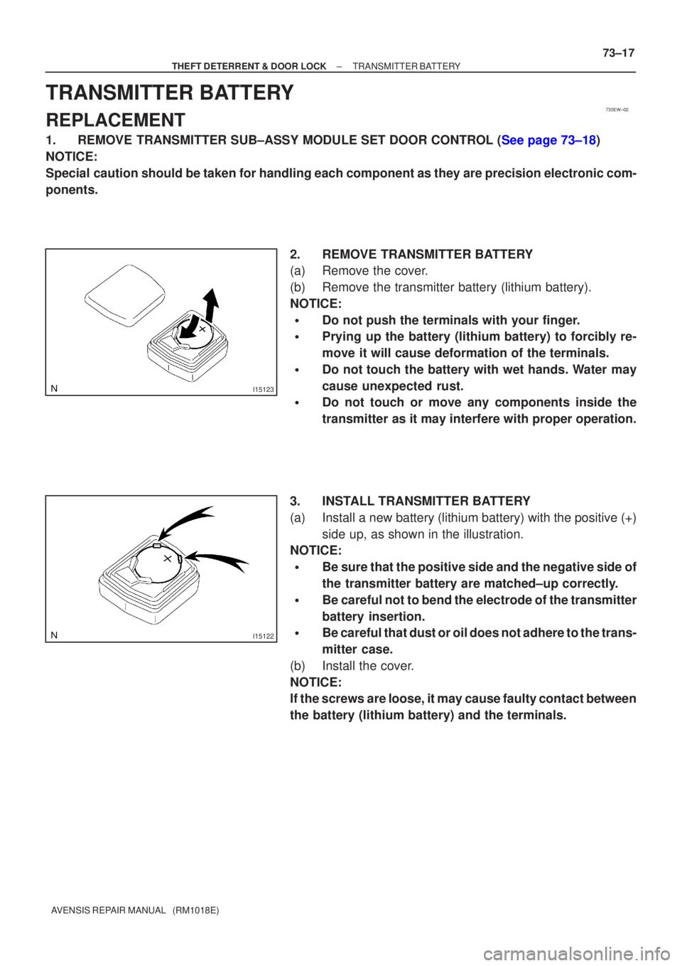
2. REMOVE TRANSMITTER BATTERY
(a) Remove the cover.
(b) Remove the transmitter battery (lithium battery).
NOTICE:
�Do not push the terminals with your finger.
�Prying up the battery (lithium battery) to forcibly re-
move it will cause deformation of the terminals.
�Do not touch the battery with wet hands. Water may
cause unexpected rust.
�Do not touch or move any components inside the
transmitter as it may interfere with proper operation.
3. INSTALL TRANSMITTER BATTERY
(a) Install a new battery (lithium battery) with the positive (+) side up, as shown in the illustration.
NOTICE:
�Be sure that the positive side and the negative side of
the transmitter battery are matched±up correctly.
�Be careful not to bend the electrode of the transmitter
battery insertion.
�Be careful that dust or oil does not adhere to the trans-
mitter case.
(b) Install the cover.
NOTICE:
If the screws are loose, it may cause faulty contact between
the battery (lithium battery) and the terminals.
Page 3393 of 5135
760WY±01
B67425
Claw
B67431
± EXTERIOR/INTERIOR TRIMFRONT BUMPER
76±3
AVENSIS REPAIR MANUAL (RM1018E)
REPLACEMENT
HINT:
The installation is in the reverse order of the removal. However, when there is a special point concerning
the installation, it is indicated.
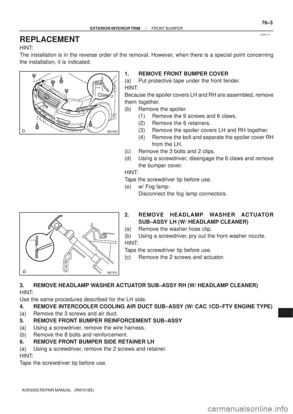
1. REMOVE FRONT BUMPER COVER
(a) Put protective tape under the front fender.
HINT:
Because the spoiler covers LH and RH are assembled, remove
them together.
(b) Remove the spoiler.
(1) Remove the 9 screws and 6 claws.
(2) Remove the 6 retainers.
(3) Remove the spoiler covers LH and RH together.
(4) Remove the bolt and separate the spoiler cover RH
from the LH.
(c) Remove the 3 bolts and 2 clips.
(d) Using a screwdriver, disengage the 6 claws and remove
the bumper cover.
HINT:
Tape the screwdriver tip before use.
(e) w/ Fog lamp:
Disconnect the fog lamp connectors.
2. R E M O V E H E A D L A M P WA S H E R A C T U ATO R
SUB±ASSY LH (W/ HEADLAMP CLEANER)
(a) Remove the washer hose clip.
(b) Using a screwdriver, pry out the front washer nozzle.
HINT:
Tape the screwdriver tip before use.
(c) Remove the 2 screws and actuator.
3. REMOVE HEADLAMP WASHER ACTUATOR SUB±ASSY RH (W/ HEADLAMP CLEANER)
HINT:
Use the same procedures described for the LH side.
4. REMOVE INTERCOOLER COOLING AIR DUCT SUB±ASSY (W/ CAC 1CD±FTV ENGINE TYPE)
(a) Remove the 3 screws and air duct.
5. REMOVE FRONT BUMPER REINFORCEMENT SUB±ASSY
(a) Using a screwdriver, remove the wire harness.
(b) Remove the 8 bolts and reinforcement.
6. REMOVE FRONT BUMPER SIDE RETAINER LH
(a) Using a screwdriver, remove the 2 screws and retainer.
HINT:
Tape the screwdriver tip before use.
Page 3394 of 5135
B67425
76±4
± EXTERIOR/INTERIOR TRIMFRONT BUMPER
AVENSIS REPAIR MANUAL (RM1018E)
7. REMOVE FRONT BUMPER SIDE RETAINER RH
HINT:
Use the same procedures described for the LH side.
8. REMOVE FRONT BUMPER STAY SUB±ASSY LH
(a) Remove the 2 bolts and stay.
9. REMOVE FRONT BUMPER STAY SUB±ASSY RH
(a) Remove the 2 bolts and stay.
10. REMOVE FOG LAMP ASSY LH (W/ FOG LAMP)
(a) Remove the 2 screws and fog lamp.
11. REMOVE FOG LAMP ASSY RH (W/ FOG LAMP)
(a) Remove the 2 screws and fog lamp.
12. REMOVE FRONT BUMPER HOLE COVER LH
13. REMOVE FRONT BUMPER HOLE COVER RH
14. REMOVE FRONT BUMPER SIDE MOULDING LH
(a) Using a screwdriver, disengage the 9 claws and remove the retainer.
HINT:
Tape the screwdriver tip before use.
15. REMOVE FRONT BUMPER SIDE MOULDING RH
HINT:
Use the same procedures described for the LH side.
16. REMOVE HOOD TO FRONT END PANEL SEAL
(a) Using a screwdriver, remove the 10 clips and panel seal.
HINT:
Tape the screwdriver tip before use.
17. REMOVE RADIATOR GRILLE
(a) Using a screwdriver, disengage the 13 claws and remove the 2 screws and radiator grille.
HINT:
Tape the screwdriver tip before use.
18. REMOVE RADIATOR GRILLE LOWER
(a) Using a screwdriver, disengage the 10 claws and remove the grille lower.
HINT:
Tape the screwdriver tip before use.
19. INSTALL FRONT BUMPER REINFORCEMENT SUB±ASSY
(a) Install the reinforcement with the 8 bolts.
(b) Install the wire harness.
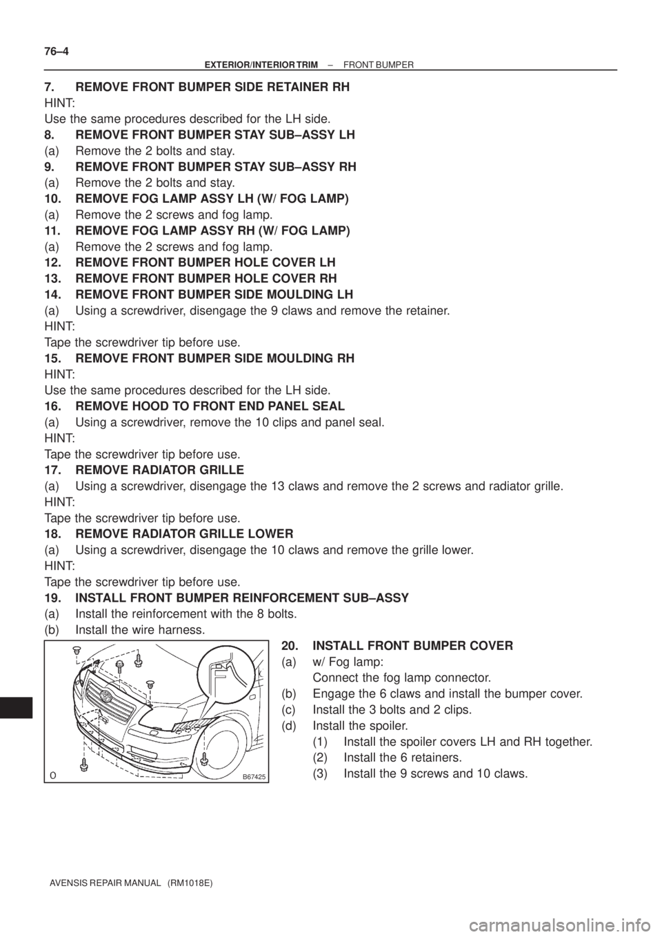
20. INSTALL FRONT BUMPER COVER
(a) w/ Fog lamp:
Connect the fog lamp connector.
(b) Engage the 6 claws and install the bumper cover.
(c) Install the 3 bolts and 2 clips.
(d) Install the spoiler.
(1) Install the spoiler covers LH and RH together.
(2) Install the 6 retainers.
(3) Install the 9 screws and 10 claws.
Page 3395 of 5135
760WX±01
B67422
Front Bumper CoverCAC Cooling
Air Duct Sub±assy Front Bumper
Reinforcement Sub±assy
Front Bumper Side
Retainer LH Front Bumper Side
Retainer RH
w/ Fog Lamp
Fog Lamp
Assy RH
Front Bumper Hole
Cover LH Front Bumper Hole
Cover RH
Front Spoiler
Cover LH Front Spoiler
Cover RHFront Bumper Side
Moulding LH Front Bumper Side
Moulding RHHood to Front
End Panel Seal Radiator GrilleRadiator Grille Lower
w/ CAC
Front Bumper
Stay Sub±assy LH Front Bumper
Stay Sub±assy RH
w/ Fog Lamp
Fog Lamp Assy LH
± EXTERIOR/INTERIOR TRIMFRONT BUMPER
76±1
AVENSIS REPAIR MANUAL (RM1018E)
FRONT BUMPER
COMPONENTS
Page 3396 of 5135
B68229
w/ Headlamp Cleaner
Headlamp Washer
Actuator Sub±assy RH
Headlamp Washer
Actuator Sub±assy LH
Radiator Grille Lower
Front Bumper Cover Headlamp Washer
Nozzle Sub±assy LH Headlamp Washer
Nozzle Sub±assy RH
Front Spoiler
Cover LH Front Spoiler
Cover RH
76±2
± EXTERIOR/INTERIOR TRIMFRONT BUMPER
AVENSIS REPAIR MANUAL (RM1018E)
Page 3399 of 5135
750N9±01
B66997: Clip
H19055Clip
B66998: Clip
������B68469: Clip
±
ENGINE HOOD/DOOR BACK DOOR(WAGON MODELS)
75±45
AVENSIS REPAIR MANUAL (RM1018E)
OVERHAUL
HINT:
The installation is in the reverse order of the removal. However, when there is a special point concerning
the installation, it is indicated.
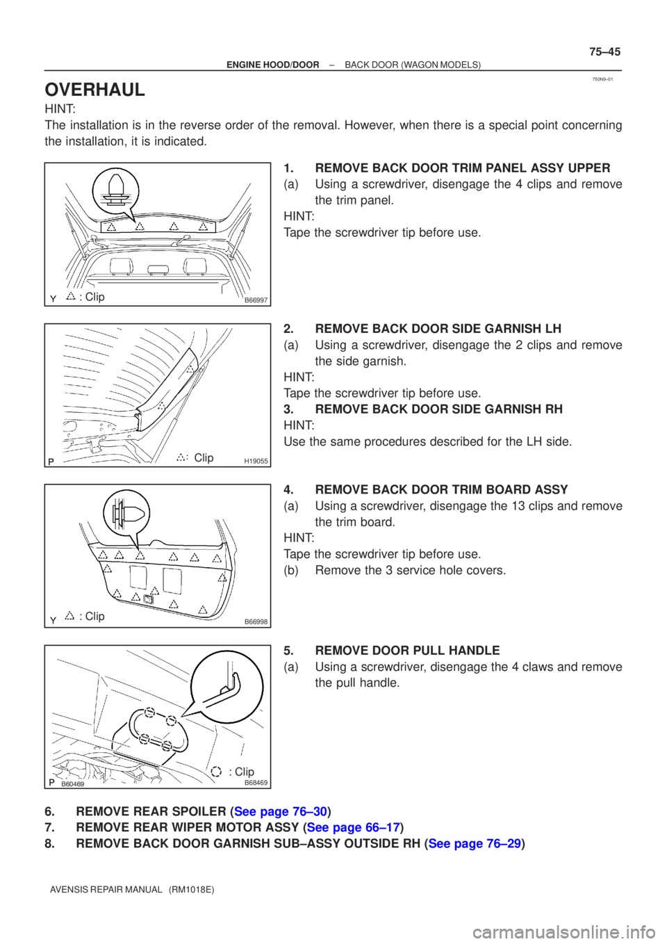
1.REMOVE BACK DOOR TRIM PANEL ASSY UPPER
(a)Using a screwdriver, disengage the 4 clips and removethe trim panel.
HINT:
Tape the screwdriver tip before use.
2.REMOVE BACK DOOR SIDE GARNISH LH
(a)Using a screwdriver, disengage the 2 clips and remove the side garnish.
HINT:
Tape the screwdriver tip before use.
3.REMOVE BACK DOOR SIDE GARNISH RH
HINT:
Use the same procedures described for the LH side.
4.REMOVE BACK DOOR TRIM BOARD ASSY
(a)Using a screwdriver, disengage the 13 clips and remove the trim board.
HINT:
Tape the screwdriver tip before use.
(b)Remove the 3 service hole covers.
5.REMOVE DOOR PULL HANDLE
(a)Using a screwdriver, disengage the 4 claws and remove the pull handle.
6.REMOVE REAR SPOILER (See page 76±30)
7.REMOVE REAR WIPER MOTOR ASSY (See page 66±17)
8.REMOVE BACK DOOR GARNISH SUB±ASSY OUTSIDE RH (See page 76±29)
Page 3403 of 5135
750N7±01
B66987
Back Door Trim Panel Assy Upper
Back Door Side Garnish LH Wiper Motor AssyRear Spoiler
Back Door Garnish Sub±assy Outside RH
Back Door Trim Board Assy
Door Pull Handle
Back Door Lock Striker Back Door Side Garnish RH
Door Pull Handle
: Specified torque
N´m (kgf´cm, ft´lbf)
Floor Finish Plate Rear Wiper Arm and Blade Assy
Wiper Arm Head Cap
5.5 (56, 49 in.´lbf)
Rear Wiper w/ Packing
Washer
Back Door
Stay Assy LH
7.0 (71, 62 in.´lbf)
22 (264, 19)
11.5 (120, 8)
Back Door Stay Assy RH
7.0 (71, 62 in.´lbf)
8.0 (82, 71 in.´lbf)
19.5 (200, 14)
Back Door Service Hole Cover
Back Door Lock Assy
4.9 (49, 43 in.´lbf)4.9 (49, 43 in.´lbf)
75±42
± ENGINE HOOD/DOORBACK DOOR (WAGON MODELS)
AVENSIS REPAIR MANUAL (RM1018E)
BACK DOOR (WAGON MODELS)
COMPONENTS
Page 3433 of 5135
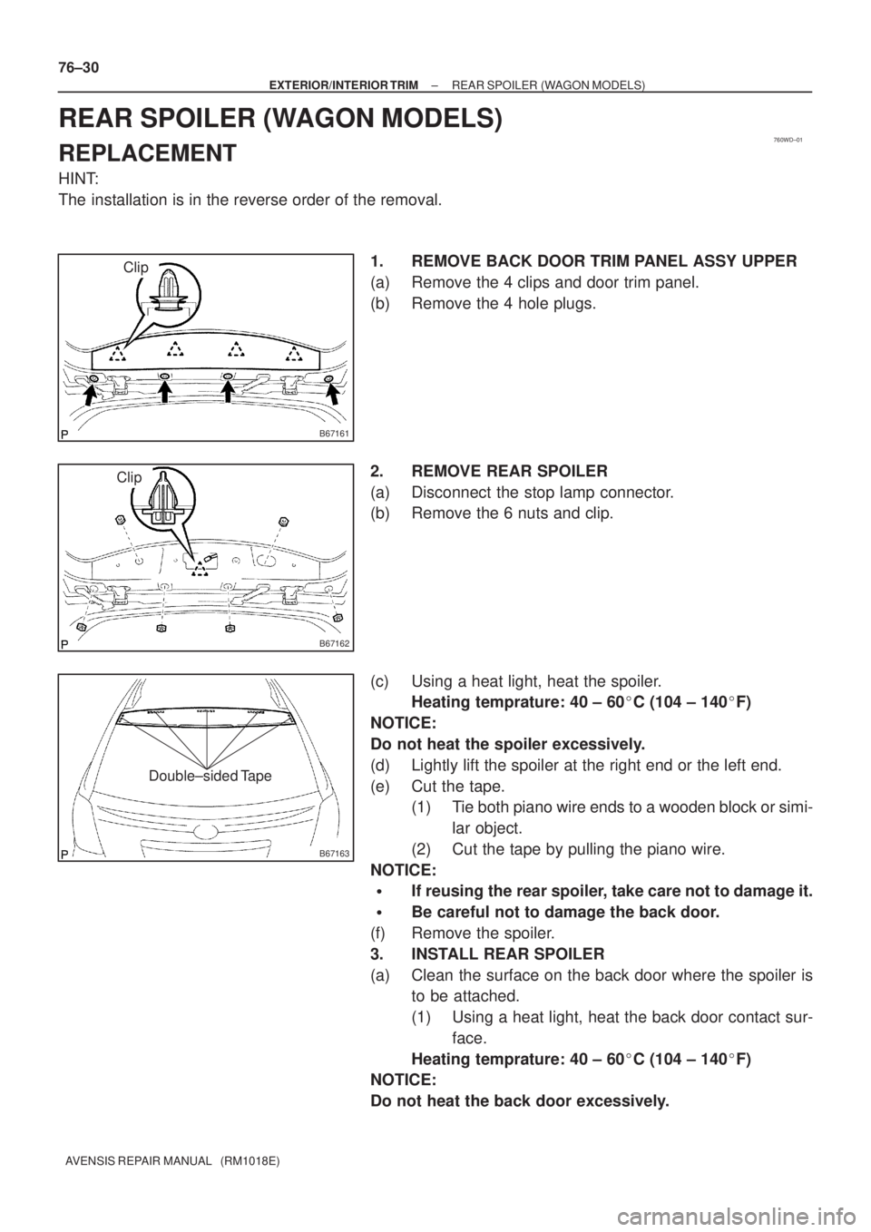
760WD±01
B67161
Clip
B67162
Clip
B67163
Double±sided Tape
76±30
± EXTERIOR/INTERIOR TRIMREAR SPOILER (WAGON MODELS)
AVENSIS REPAIR MANUAL (RM1018E)
REAR SPOILER (WAGON MODELS)
REPLACEMENT
HINT:
The installation is in the reverse order of the removal.
1. REMOVE BACK DOOR TRIM PANEL ASSY UPPER
(a) Remove the 4 clips and door trim panel.
(b) Remove the 4 hole plugs.
2. REMOVE REAR SPOILER
(a) Disconnect the stop lamp connector.
(b) Remove the 6 nuts and clip.
(c) Using a heat light, heat the spoiler.
Heating temprature: 40 ± 60�C (104 ± 140�F)
NOTICE:
Do not heat the spoiler excessively.
(d) Lightly lift the spoiler at the right end or the left end.
(e) Cut the tape.
(1) Tie both piano wire ends to a wooden block or simi-
lar object.
(2) Cut the tape by pulling the piano wire.
NOTICE:
�If reusing the rear spoiler, take care not to damage it.
�Be careful not to damage the back door.
(f) Remove the spoiler.
3. INSTALL REAR SPOILER
(a) Clean the surface on the back door where the spoiler is
to be attached.
(1) Using a heat light, heat the back door contact sur-
face.
Heating temprature: 40 ± 60�C (104 ± 140�F)
NOTICE:
Do not heat the back door excessively.