Page 2883 of 5135

Open
Lock Position
F08858
±
POWER STEERING POWER STEERING SYSTEM
51±7
AVENSIS REPAIR MANUAL (RM1018E)
(k) With the engine idling and valve fully ope")
Z15500
Oil
ReservoirPS Vane
Pump
PS Gear
SST(s)
Open
Lock Position
F08858
±
POWER STEERING POWER STEERING SYSTEM
51±7
AVENSIS REPAIR MANUAL (RM1018E)
(k) With the engine idling and valve fully opened, turn the
steering wheel to full lock position.
Minimum fluid pressure:
AZ Series:
8,300 to 9,000 kPa (85 to 92 kgf/cm
2, 1,204 to 1,305 psi)
1CD±FTV:
8,800 to 9,500 kPa (90 to 97 kgf/cm
2, 1,276 to 1,378 psi)
NOTICE:
�Do not maintain lock position for more than 10 se-
conds.
�Do not let the fluid temperature become too high.
(l) Remove SST(s).
(m) AZ Series:
Connect the pressure feed tube assy to the vane pump
assy (See page 51±9).
(n) 1CD±FTV:
Connect the pressure feed tube assy to the vane pump
assy (See page 51±19).
(o) Bleed the power steering system.
5. CHECK STEERING EFFORT
(a) Center the steering wheel.
(b)Remove the steering wheel pad (See page 60±17).
(c) Start the engine and run it at idle.
(d) Measure the steering effort in both directions. Steering effort (Reference):
5.5 N´m (56 kgf´cm, 49 in.´lbf)
HINT:
Take the tire type, pressure and contact surface into consider-
ation before making your diagnosis.
(e) Torque the steering wheel set nut. Torque: 50 N´m (510 kgf´cm, 37 ft´lbf)
(f)Install the steering wheel pad (See page 60±17).
Page 2885 of 5135
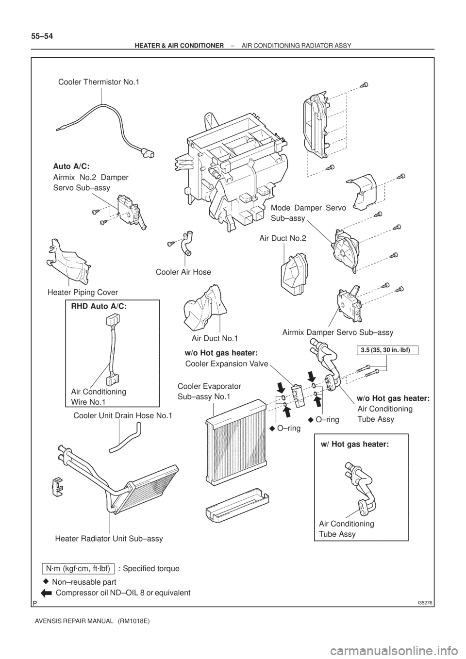
I35276
N�m (kgf�cm, ft�lbf) : Specified torque
Non±reusable part �
Compressor oil ND±OIL 8 or equivalentCooler Thermistor No.1
Auto A/C:
Airmix No.2 Damper
Servo Sub±assy
Heater Piping CoverMode Damper Servo
Sub±assy
Airmix Damper Servo Sub±assy
w/o Hot gas heater:
Cooler Expansion Valve
Cooler Evaporator
Sub±assy No.1
Cooler Unit Drain Hose No.1
Air Conditioning
Tube Assy
Heater Radiator Unit Sub±assyAir Duct No.1Air Duct No.2
w/o Hot gas heater:
Air Conditioning
Tube Assy
w/ Hot gas heater:
O±ring
�
O±ring
�
3.5 (35, 30 in.�lbf)
Cooler Air Hose
RHD Auto A/C:
Air Conditioning
Wire No.1
55±54
± HEATER & AIR CONDITIONERAIR CONDITIONING RADIATOR ASSY
AVENSIS REPAIR MANUAL (RM1018E)
Page 2900 of 5135
 Amount to be charged
Sub±cool system RHD AZ Engine series: 55±38
± HEATER & AIR CO")
550Z8±01
������I37091
Over charged Mean
value
in proper
range
Hight
Pressure
Refrigerant Amount� 30 g (�1.06 oz.) Amount to be charged
Sub±cool system RHD AZ Engine series: 55±38
± HEATER & AIR CONDITIONERREFRIGERANT
AVENSIS REPAIR MANUAL (RM1018E)
REPLACEMENT
1. DISCHARGE REFRIGERANT FROM REFRIGERATION SYSTEM
(a) Turn the A/C switch ON.
(b) Operate the cooler compressor at the engine rpm of approx. 1,000 for 5 to 6 minuites to circulate the
refrigerant and collect the compressor oil remaining in each component into the cooler compressor as
much as possible.
(c) Shut off the engine.
(d) Let the refrigerant gas out.
SST 07110±58060 (07117±58080, 07117±58090, 07117±78050, 07117±88060, 07117±88070,
07117±88080)
2. CHARGE REFRIGERANT
(a) Using a vacuum pump, perform vacuuming.
(b) Charge refrigerant, HFC±134a (R134a).
Standard: 440 � 30 g (15.51 � 1.06 oz.)
SST 07110±58060 (07117±58060, 07117±58070, 07117±58080, 07117±58090, 07117±78050,
07117±88060, 07117±88070, 07117±88080)
3. WARM UP ENGINE
4. INSPECT LEAKAGE OF REFRIGERANT
(a) Using a gas leak detector, check for leakage of the refrigerant.
NOTICE:
1CD±FTV Hot gas heater:
Since the system uses a refrigerant filter (fixed valve), sound of the refrigerant circulation (hissing
sound) can be heard for approx. 30 seconds after turning the A/C off. This is merely a sound of bal-
ancing the low pressure with the high pressure, not a sound of abnormality.
Page 2906 of 5135

I22122
Condition: Air conditioning system does not function.
NOTE : These gauge indica-
tions occur when the refrigera-
tion system opens and the re-
frigerant is charged without
vacuuming.
I22123
Condition
: Air conditioning system does not function effectively.
± HEATER & AIR CONDITIONERREFRIGERANT
55±29
AVENSIS REPAIR MANUAL (RM1018E)
(7) When there is air in the refrigeration system:
SymptomProbable causeDiagnosisCorrective Actions
� Pressure is extreamly high on
both low and the high pressure
sides
� The low pressure piping is too
hot to touch
� RHD AZ engine series:
Bubbles can be seen through sight
glass
Air in refrigeration system
� There is air in refrigeration sys-
tem
� Vacuuming is insufficient
(1) Check it compressor oil is dirty
or insufficient
(2) Vacuum and supply new refrig-
erant
(8) When the expansion valve malfunctions:
SymptomProbable causeDiagnosisCorrective Actions
� Pressure is extreamly high on
both low and high pressure sides
� Frost or dew is on piping on low
pressure side
Trouble with expansion valve
� Excessive refrigerant in low
pressure piping
� Expansion valve opened too
wide
Replace expansion valve
Page 2913 of 5135
I22122
Condition
NOTE : These gauge indica-
tions occur when the refrigera-
tion system opens and the re-
frigerant is charged without
vacuuming. : Air conditioning system does not function.
I22123
Condition : Air conditioning system does not function effectively. 55±36
± HEATER & AIR CONDITIONERREFRIGERANT
AVENSIS REPAIR MANUAL (RM1018E)
(7) When there is air in the refrigeration system:
SymptomProbable causeDiagnosisCorrective Actions
Pressure is extreamly high on both
low and the high pressure sidesAir in refrigeration system
� There is air in refrigeration sys-
tem
� Vacuuming is insufficient(1) Check if compressor oil is dirty
or insufficient
(2) Vacuum air and supply new re-
frigerant
(8) When the refrigerant filter is defective:
SymptomProbable causeDiagnosisCorrective Actions
� Pressure is extreamly high on
low pressure side
� Pressure is extreamly high on
high pressure side
Trouble with refrigerant filterExcessive refrigerantReplace refrigerant filter
Page 2934 of 5135
(2)
(3)
(4)
±
HEATER & AIR CONDITIONER W/PULLEY COMPRESSOR ASSY (1CD±FTV)
55±87
AVENSIS REPAIR MANUAL (RM1018E)
10. REMOVE W/PULLEY COMPRESSOR ASSY
(a) Disconnect the connector.")
I35333
I35333
(1)(2)
(3)
(4)
±
HEATER & AIR CONDITIONER W/PULLEY COMPRESSOR ASSY (1CD±FTV)
55±87
AVENSIS REPAIR MANUAL (RM1018E)
10. REMOVE W/PULLEY COMPRESSOR ASSY
(a) Disconnect the connector.
(b) Remove the 4 bolts and the w/pulley compressor assy.
11. INSPECT COMPRESSOR OIL
(a) When replacing the w/pulley compressor assy with a new one, after gradually \
removing the refrigerant gas from the service valve, drain the following amount of oil from the new w\
/pulley compressor assy
before installation.
Standard:
(Oil capacity inside new w/pulley compressor assy: 90 + 15 cc (3.0 + 0.5 fl. oz.) ) ± (Remaining
oil amount in the removed w/pulley compressor assy) = (Oil amount to be r\
emoved when replac-
ing)
NOTICE:
�When checking the compressor oil level, observe the precautions on the cooler removal/inst\
al-
lation.
�Since compressor oil remains in the pipes of the vehicle, if a new w/pulley c\
ompressor assy
is installed without removing some oil inside, the oil amount becomes ex\
cessive, preventing
heat exchange in the refrigerant cycle and causing refrigerant failure.
�If the remaining oil in the removed w/pulley compressor assy is too smal\
l in volume, check for
oil leakage.
�Be sure to use ND±OIL 8 for compressor oil.
12. INSTALL W/PULLEY COMPRESSOR ASSY
(a) Install the w/pulley compressor assy with the 4 bolts.Torque: 29 N �m (300 kgf �cm, 21 ft �lbf)
NOTICE:
Tighten the bolts in the order shown in the illustration to
install the w/pulley compressor assy.
(b) Connect the connector.
13. INSTALL V (COOLER COMPRESSOR TO CRANKSHAFT PULLEY) BELT NO.1 (See page 55±46)
14. ADJUST V (COOLER COMPRESSOR TO CRANKSHAFT PULLEY) BELT NO.1
(See page 55±46)
15. FULLY TIGHTEN V (COOLER COMPRESSOR TO CRANKSHAFT PULLEY) BELT NO.1 (See page 55±46)
Page 2935 of 5135

AVENSIS REPAIR MANUAL (RM1018E)
16. INSTALL COOLER REFRIGERANT DISCHARGE
HOSE NO.1
(a) Remove the attached")
I35332
I35330
I35331
55±88
± HEATER & AIR CONDITIONERW/PULLEY COMPRESSOR ASSY (1CD±FTV)
AVENSIS REPAIR MANUAL (RM1018E)
16. INSTALL COOLER REFRIGERANT DISCHARGE
HOSE NO.1
(a) Remove the attached vinyl tape from the hose.
(b) Sufficiently apply compressor oil to a new O±ring and the
fitting surface of the w/pulley compressor assy.
Compressor oil: ND±OIL 8 or equivalent
(c) Install the O±ring on the cooler refrigerant discharge hose
No.1.
(d) Install the cooler refrigerant discharge hose No.1 on the
w/pulley compressor assy with the bolt.
Torque: 9.8 N�m (100 kgf�cm, 87 in.�lbf)
17. INSTALL COOLER REFRIGERANT SUCTION HOSE
NO.1 (RHD STEERING POSITION TYPE)
(a) Remove the attached vinyl tape from the hose.
(b) Sufficiently apply compressor oil to a new O±ring and the
fitting surface of the w/pulley compressor assy.
Compressor oil: ND±OIL 8 or equivalent
(c) Install the O±ring on the cooler refrigerant suction hose
No.1.
(d) Install the cooler refrigerant suction hose No.1 on the w/
pulley compressor assy with the bolt.
Torque: 9.8 N�m (100 kgf�cm, 87 in.�lbf)
18. INSTALL SUCTION SERVIC VALVE (LHD STEERING
POSITION TYPE)
(a) Remove the attached vinyl tape from the hose.
(b) Sufficiently apply compressor oil to a new O±ring and the
fitting surface of the w/pulley compressor assy.
Compressor oil: ND±OIL 8 or equivalent
(c) Install the O±ring on the suction service valve.
(d) Install the suction servic valve on the w/pulley compres-
sor assy with the 2 bolts.
Torque: 9.8 N�m (100 kgf�cm, 87 in.�lbf)
19. INSTALL COOLER REFRIGERANT SUCTION HOSE
NO.1 (LHD STEERING POSITION TYPE)
(a) Remove the attached vinyl tape from the hose.
(b) Sufficiently apply compressor oil to a new O±ring and the
fitting surface of the w/pulley compressor assy.
Compressor oil: ND±OIL 8 or equivalent
(c) Install the O±ring on the cooler refrigerant suction hose
No.1.
Page 2938 of 5135

AVENSIS REPAIR MANUAL (RM1018E)
REPLACEMENT
1.DISCHARGE REFRIGERANT FROM REFRIGERATION SYSTEM (Se")
550Z4±01
I35326
I35327
I35328
55±82
±
HEATER & AIR CONDITIONER W/PULLEY COMPRESSOR ASSY (1AZ±FE)
AVENSIS REPAIR MANUAL (RM1018E)
REPLACEMENT
1.DISCHARGE REFRIGERANT FROM REFRIGERATION SYSTEM (See page 55±38) SST 07110±58060 (07117±58080, 07117±58090, 07117±78050, 07117±88060, 07117±88070, 07117±88080)
2. DISCONNECT COOLER REFRIGERANT SUCTIONHOSE NO.1
(a) Remove the bolt and disconnect the cooler refrigerant suction hose No.1 from the w/pulley compressor assy.
(b) Remove the O±ring from the cooler refrigerant suction hose No.1.
NOTICE:
Seal the opening of the disconnected parts using vinyl tape
to prevent moisture and foreign matters from entering.
3. DISCONNECT COOLER REFRIGERANT DISCHARGE
HOSE NO.1
(a) Remove the bolt and disconnect the cooler refrigerant discharge hose No.1 from the w/pulley compressor assy.
(b) Remove the O±ring from the cooler refrigerant discharge
hose No.1.
NOTICE:
Seal the opening of the disconnected parts using vinyl tape
to prevent moisture and foreign matters from entering.
4.REMOVE RADIATOR SUPPORT OPENING COVER (See page 14±105)
5.REMOVE ENGINE ROOM COVER SIDE (See page 14±105)
6.REMOVE ENGINE UNDER COVER RH (See page 14±105)
7.REMOVE FAN AND GENERATOR V BELT (See page 14±105) SST 09249±63010 8. REMOVE W/PULLEY COMPRESSOR ASSY
(a) Disconnect the connector.
(b) Remove the 4 bolts and the w/pulley compressor assy.
9. INSPECT COMPRESSOR OIL
(a) When replacing the w/pulley compressor assy with a new one, after gradually \
removing the refrigerant gas from the service valve, drain the following amount of oil from the new w\
/pulley compressor assy
before installation.
Standard:
(Oil capacity inside new w/pulley compressor assy: 90 + 15 cc (3.0 + 0.5 fl. oz.) ) ± (Remaining
oil amount in the removed w/pulley compressor assy) = (Oil amount to be r\
emoved when replac-
ing)