Page 2795 of 5135
D30480
±
MANUAL TRANSMISSION/TRANSAXLE MANUAL TRANSAXLE ASSY (1ZZ±FE/3ZZ±FE)
41±21
AVENSIS REPAIR MANUAL (RM1018E)
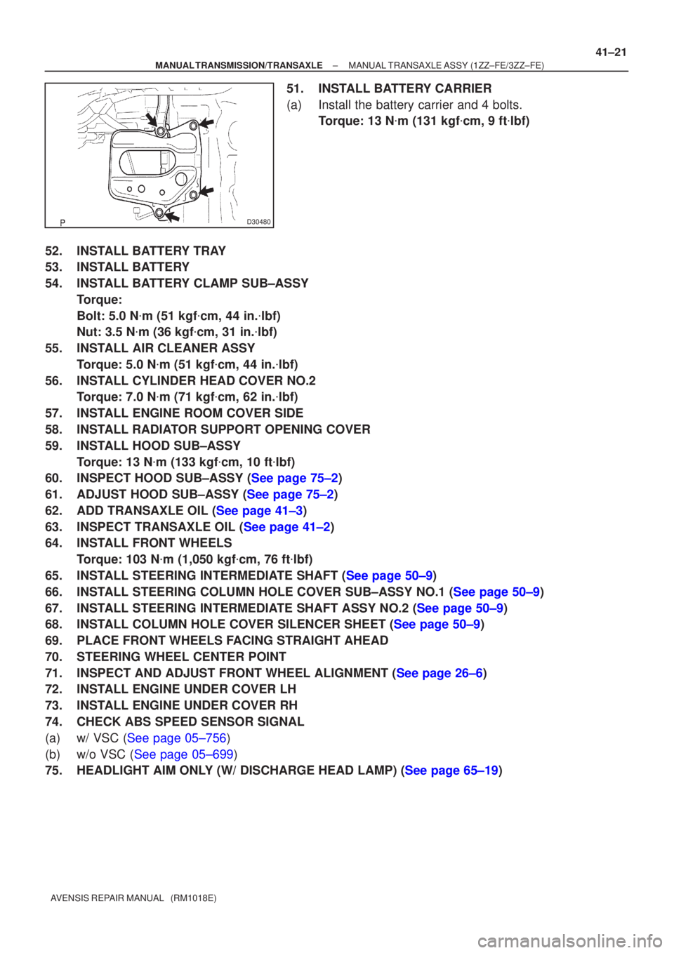
51. INSTALL BATTERY CARRIER
(a) Install the battery carrier and 4 bolts.
Torque: 13 N �m (131 kgf �cm, 9 ft �lbf)
52. INSTALL BATTERY TRAY
53. INSTALL BATTERY
54. INSTALL BATTERY CLAMP SUB±ASSY Torque:
Bolt: 5.0 N �m (51 kgf �cm, 44 in. �lbf)
Nut: 3.5 N �m (36 kgf �cm, 31 in. �lbf)
55. INSTALL AIR CLEANER ASSY Torque: 5.0 N �m (51 kgf �cm, 44 in. �lbf)
56. INSTALL CYLINDER HEAD COVER NO.2 Torque: 7.0 N �m (71 kgf �cm, 62 in. �lbf)
57. INSTALL ENGINE ROOM COVER SIDE
58. INSTALL RADIATOR SUPPORT OPENING COVER
59. INSTALL HOOD SUB±ASSY Torque: 13 N �m (133 kgf �cm, 10 ft �lbf)
60.INSPECT HOOD SUB±ASSY (See page 75±2)
61.ADJUST HOOD SUB±ASSY (See page 75±2)
62.ADD TRANSAXLE OIL (See page 41±3)
63.INSPECT TRANSAXLE OIL (See page 41±2)
64. INSTALL FRONT WHEELS
Torque: 103 N �m (1,050 kgf �cm, 76 ft �lbf)
65.INSTALL STEERING INTERMEDIATE SHAFT (See page 50±9)
66.INSTALL STEERING COLUMN HOLE COVER SUB±ASSY NO.1 (See page 50±9)
67.INSTALL STEERING INTERMEDIATE SHAFT ASSY NO.2 (See page 50±9)
68.INSTALL COLUMN HOLE COVER SILENCER SHEET (See page 50±9)
69. PLACE FRONT WHEELS FACING STRAIGHT AHEAD
70. STEERING WHEEL CENTER POINT
71.INSPECT AND ADJUST FRONT WHEEL ALIGNMENT (See page 26±6)
72. INSTALL ENGINE UNDER COVER LH
73. INSTALL ENGINE UNDER COVER RH
74. CHECK ABS SPEED SENSOR SIGNAL
(a)w/ VSC (See page 05±756)
(b)w/o VSC (See page 05±699)
75.HEADLIGHT AIM ONLY (W/ DISCHARGE HEAD LAMP) (See page 65±19)
Page 2810 of 5135
F44798
F44799
F44793Matchmarks
±
STEERING COLUMN STEERING COLUMN ASSY
50±15
AVENSIS REPAIR MANUAL (RM1018E)
38. REMOVE UN±LOCK WARNING SWITCH ASSY
(a) Slide the unlock warning switch assy out of the steering column upper br\
acket.
39. REMOVE IGNITION OR STARTER SWITCH ASSY
(a) Remove the 2 screws and ignition or starter switch assy.
40. INSTALL IGNITION OR STARTER SWITCH ASSY
(a) Install the ignition or starter switch assy to the steering column upper w/swit\
ch bracket assy with the
2 screws.
41. INSTALL UN±LOCK WARNING SWITCH ASSY
(a) Install the un±lock warning switch assy.
(b) Connect the un±lock warning switch assy connector to the ignition or \
starter switch assy.
42. INSTALL IGNITION SWITCH LOCK CYLINDER ASSY
(a) Make sure of the ignition switch lock cylinder assy at the ACC position.\
(b) Install the ignition switch lock cylinder assy.
43. INSPECT STEERING LOCK OPERATION
(a) Check that the steering lock mechanism is activated when removing the ke\
y.
(b) Check that the steering lock mechanism is deactivated when inserting the\
key and turning it to ACC position.
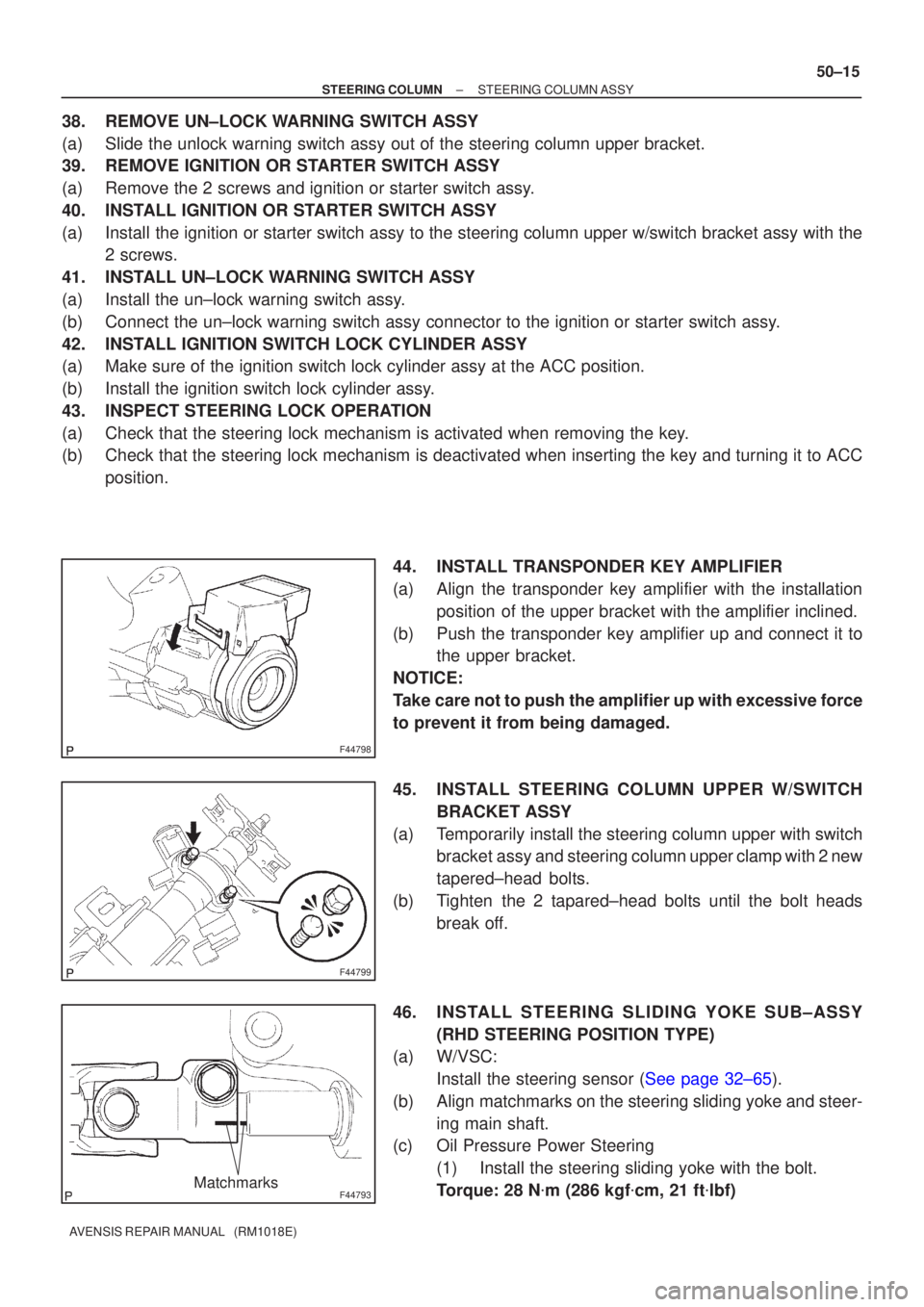
44. INSTALL TRANSPONDER KEY AMPLIFIER
(a) Align the transponder key amplifier with the installationposition of the upper bracket with the amplifier inclined.
(b) Push the transponder key amplifier up and connect it to the upper bracket.
NOTICE:
Take care not to push the amplifier up with excessive force
to prevent it from being damaged.
45. INSTALL STEERING COLUMN UPPER W/SWITCH BRACKET ASSY
(a) Temporarily install the steering column upper with switch bracket assy and steering column upper clamp with 2 new
tapered±head bolts.
(b) Tighten the 2 tapared±head bolts until the bolt heads break off.
46. INSTALL STEERING SLIDING YOKE SUB±ASSY (RHD STEERING POSITION TYPE)
(a) W/VSC:
Install the steering sensor (See page 32±65).
(b) Align matchmarks on the steering sliding yoke and steer- ing main shaft.
(c) Oil Pressure Power Steering
(1) Install the steering sliding yoke with the bolt.
Torque: 28 N �m (286 kgf �cm, 21 ft �lbf)
Page 2811 of 5135
F44793Matchmarks
F44789
RHD:
Matchmarks
A
B
F45709
50−16
−
STEERING COLUMN STEERING COLUMN ASSY
(d) Electric Pressure Power Steering
(1) Install the steering sliding yoke with the bolt.
Torque: 35 N �m (360 kgf�cm, 26 ft �lbf)
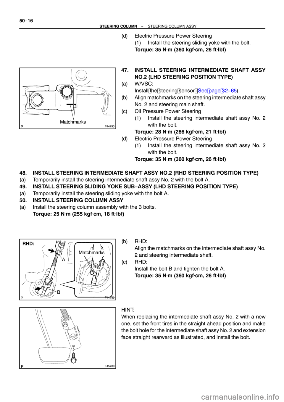
47. INSTALL STEERING INTERMEDIATE SHAFT ASSY NO.2 (LHD STEERING POSITION TYPE)
(a) W/VSC:
Install the steering sensor (See page 32− 65).
(b) Align matchmarks on the steering intermediate shaft assy
No. 2 and steering main shaft.
(c) Oil Pressure Power Steering (1) Install the steering intermediate shaft assy No. 2
with the bolt.
Torque: 28 N �m (286 kgf�cm, 21 ft �lbf)
(d) Electric Pressure Power Steering (1) Install the steering intermediate shaft assy No. 2
with the bolt.
Torque: 35 N �m (360 kgf�cm, 26 ft �lbf)
48. INSTALL STEERING INTERMEDIATE SHAFT ASSY NO.2 (RHD STEERING POSITION TYPE)
(a) Temporarily install the steering intermediate shaft assy No. 2 with the bolt A.
49. INSTALL STEERING SLIDING YOKE SUB −ASSY (LHD STEERING POSITION TYPE)
(a) Temporarily install the steering sliding yoke with the bolt A.
50. INSTALL STEERING COLUMN ASSY
(a) Install the steering column assembly with the 3 bolts.
Torque: 25 N �m (255 kgf�cm, 18 ft �lbf)
(b) RHD: Align the matchmarks on the intermediate shaft assy No.
2 and steering intermediate shaft.
(c) RHD: Install the bolt B and tighten the bolt A.
Torque: 35 N �m (360 kgf�cm, 26 ft �lbf)
HINT:
When replacing the intermediate shaft assy No. 2 with a new
one, set the front tires in the straight ahead position and make
the bolt hole for the intermediate shaft assy No. 2 and extension
face straight rearward as illustrated, and install the bolt.
Page 2815 of 5135
5006X−01
Steering
Column
Protector No.1
F44781
Horn Button Assy
Steering Wheel Assy
Spiral Cable Sub −Assy
Steering Column Cover
Headlamp Dimmer Switch AssySteering Column Assy
Steering
Sliding Yoke
Sub− Assy
Steering Intermediate
Shaft Assy No.2
Column Hole Cover Silencer Sheet
Steering Column Cover LWR
Windshield Wiper
Switch Assy
N
�m (kgf �cm, ft�lbf): Specified torque
OIL Pressure Power Steering:
Steering Intermediate
Shaft Assy No.2
Steering
Sliding Yoke
Sub−Assy
35 (360, 26)
Column Hole Cover
Silencer Sheet
LHD Steering Position Type:
LHD Steering Position
Type: w/ Instrument Cluster
Finish Panel Assy
Floor Shift
Parking Lock Cable
Assy (A/T Transaxle)
Instrument Panel
Hole Cover
5 (51, 44 in.�
�� � lbf)
18 (184, 13)
18 (184, 13)
Instrument Panel
Airbag Assy
18 (184, 13)
18 (184, 13)
18 (184, 13)
25 (255, 18)
50 (510, 37)
35 (360, 26)
35 (360, 26)
28 (286, 21)
35 (360, 26)
28 (286, 21)
25 (255, 18)
25 (255, 18)
−
STEERING COLUMN STEERING COLUMN ASSY
50−5
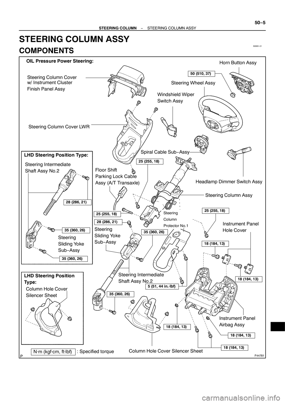
STEERING COLUMN ASSY
COMPONENTS
Page 2820 of 5135
5000D±14
50±2
±
STEERING COLUMN STEERING SYSTEM
AVENSIS REPAIR MANUAL (RM1018E)
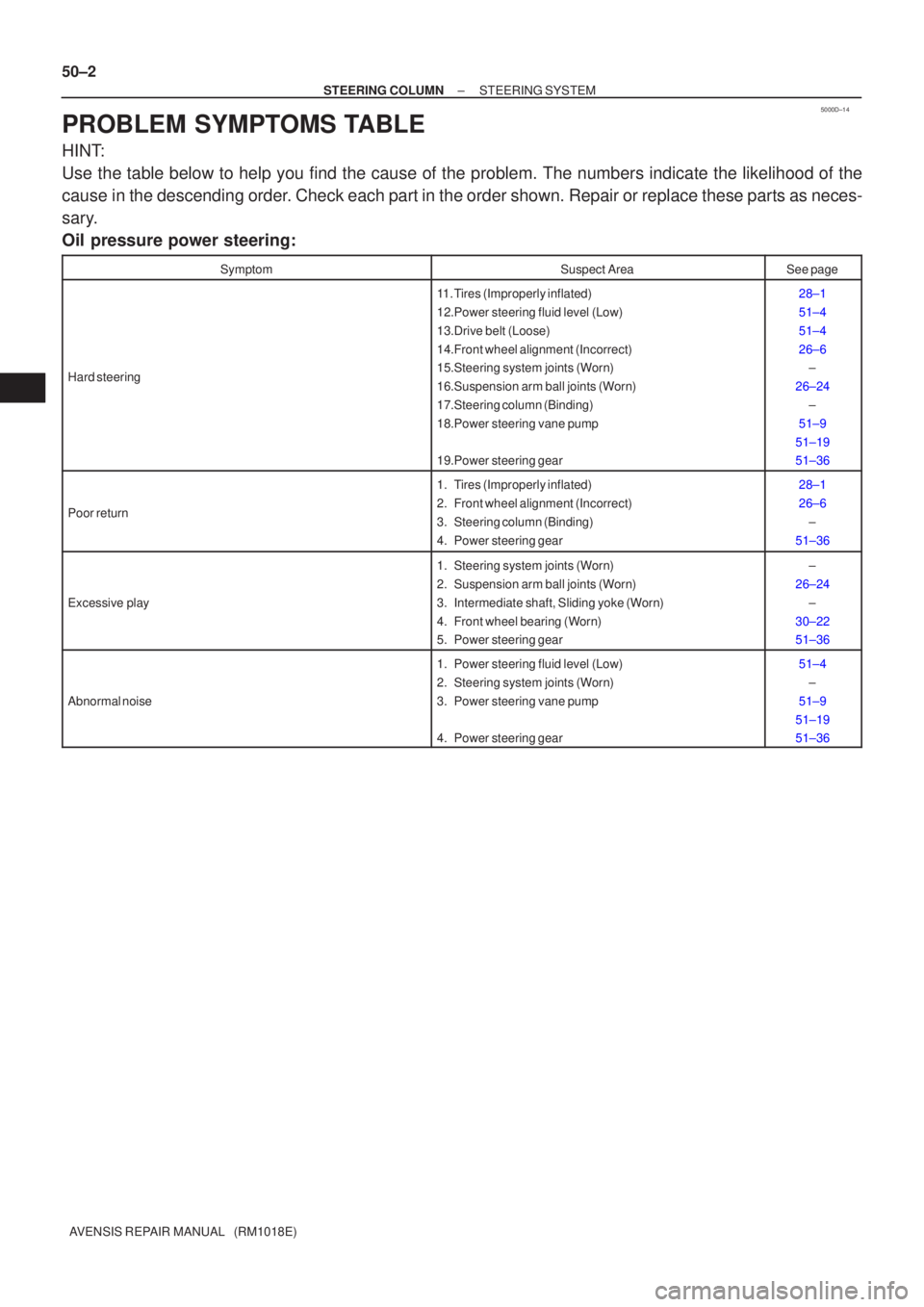
PROBLEM SYMPTOMS TABLE
HINT:
Use the table below to help you find the cause of the problem. The numbers \
indicate the likelihood of the
cause in the descending order. Check each part in the order shown. Repair or replace these parts as n\
eces-
sary.
Oil pressure power steering:
SymptomSuspect AreaSee page
Hard steering
11. Tires (Improperly inflated)
12.Power steering fluid level (Low)
13.Drive belt (Loose)
14.Front wheel alignment (Incorrect)
15.Steering system joints (Worn)
16.Suspension arm ball joints (Worn)
17.Steering column (Binding)
18.Power steering vane pump
19.Power steering gear28±1
51±4
51±4
26±6 ±
26±24 ±
51±9
51±19
51±36
Poor return
1. Tires (Improperly inflated)
2. Front wheel alignment (Incorrect)
3. Steering column (Binding)
4. Power steering gear28±1
26±6 ±
51±36
Excessive play
1. Steering system joints (Worn)
2. Suspension arm ball joints (Worn)
3. Intermediate shaft, Sliding yoke (Worn)
4. Front wheel bearing (Worn)
5. Power steering gear±
26±24 ±
30±22
51±36
Abnormal noise
1. Power steering fluid level (Low)
2. Steering system joints (Worn)
3. Power steering vane pump
4. Power steering gear51±4 ±
51±9
51±19
51±36
Page 2824 of 5135
C62956
D30058
1CD±FTV Engine Type: Others:
Transaxle Side
������
D25281
AB
C62958
± CLUTCHCLUTCH UNIT (MTM)
42±27
AVENSIS REPAIR MANUAL (RM1018E)
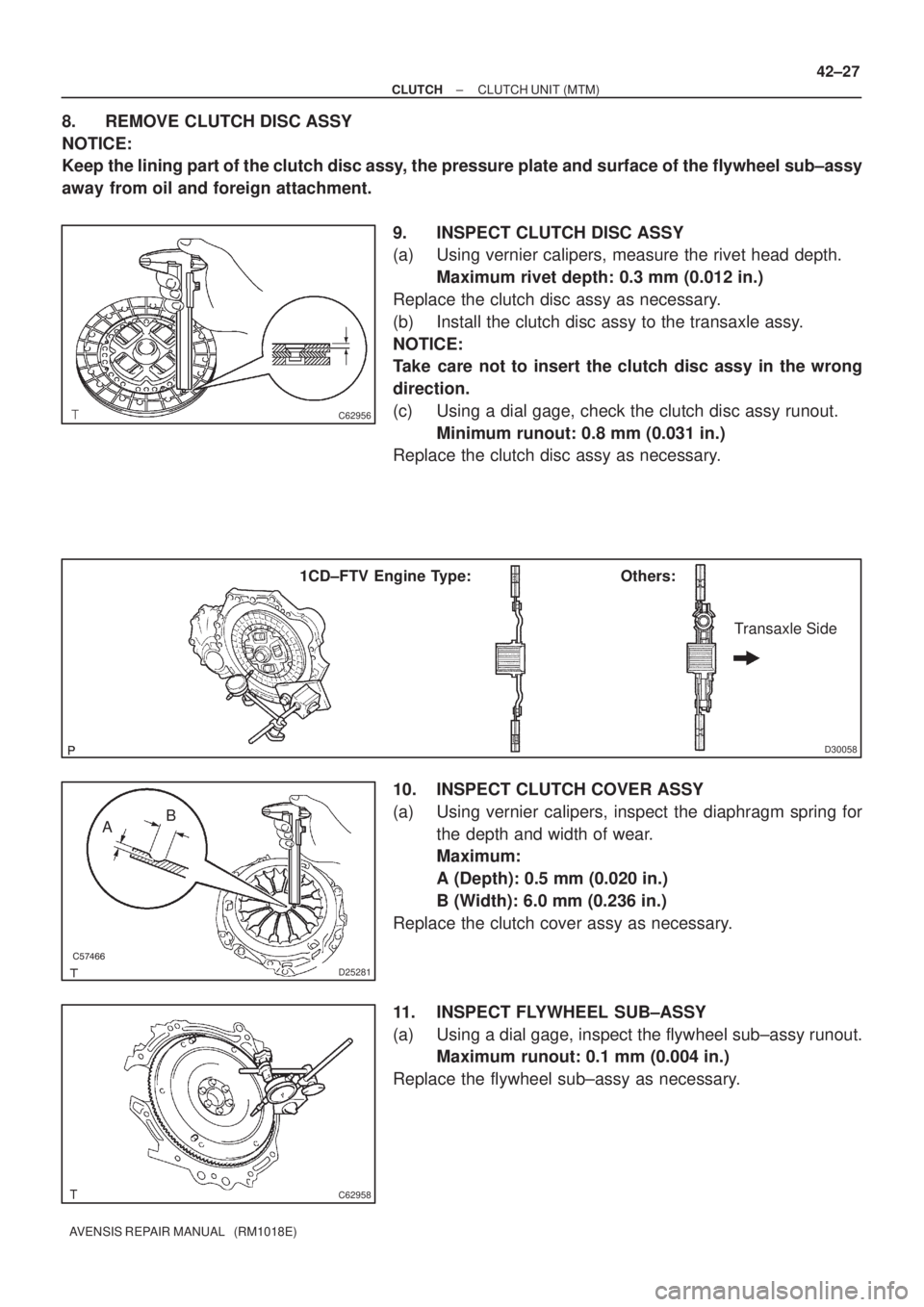
8. REMOVE CLUTCH DISC ASSY
NOTICE:
Keep the lining part of the clutch disc assy, the pressure plate and surface of the flywheel sub±assy
away from oil and foreign attachment.
9. INSPECT CLUTCH DISC ASSY
(a) Using vernier calipers, measure the rivet head depth.
Maximum rivet depth: 0.3 mm (0.012 in.)
Replace the clutch disc assy as necessary.
(b) Install the clutch disc assy to the transaxle assy.
NOTICE:
Take care not to insert the clutch disc assy in the wrong
direction.
(c) Using a dial gage, check the clutch disc assy runout.
Minimum runout: 0.8 mm (0.031 in.)
Replace the clutch disc assy as necessary.
10. INSPECT CLUTCH COVER ASSY
(a) Using vernier calipers, inspect the diaphragm spring for
the depth and width of wear.
Maximum:
A (Depth): 0.5 mm (0.020 in.)
B (Width): 6.0 mm (0.236 in.)
Replace the clutch cover assy as necessary.
11. INSPECT FLYWHEEL SUB±ASSY
(a) Using a dial gage, inspect the flywheel sub±assy runout.
Maximum runout: 0.1 mm (0.004 in.)
Replace the flywheel sub±assy as necessary.
Page 2840 of 5135
5507E±03
AC2810
AC2811
N11084
Wrong Okay
HI
LO HI LO
± HEATER & AIR CONDITIONERAIR CONDITIONING SYSTEM
55±1
AVENSIS REPAIR MANUAL (RM1018E)
AIR CONDITIONING SYSTEM
PRECAUTION
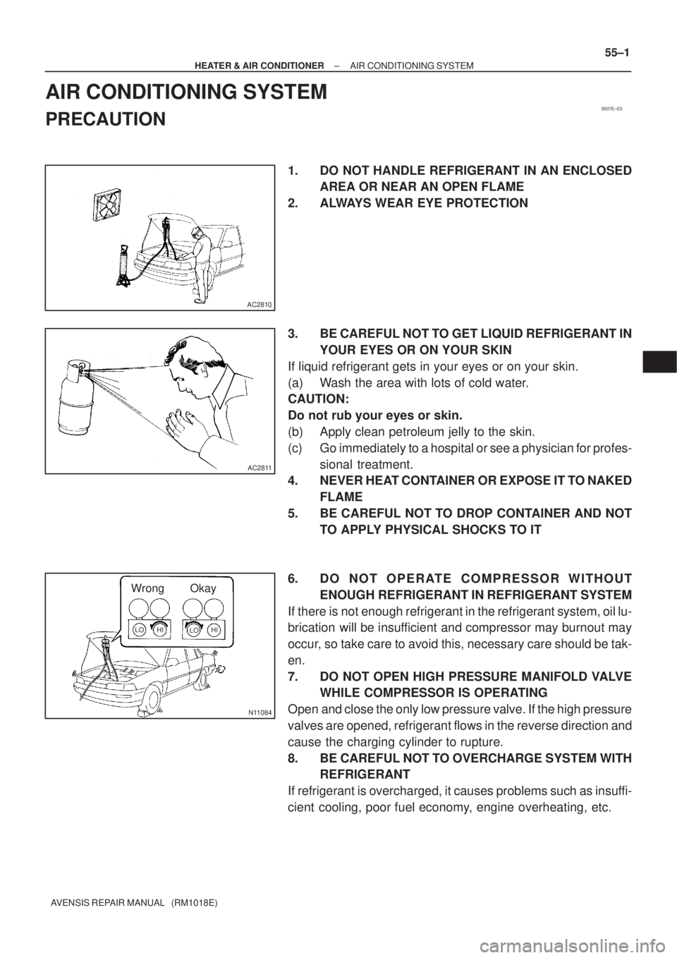
1. DO NOT HANDLE REFRIGERANT IN AN ENCLOSED
AREA OR NEAR AN OPEN FLAME
2. ALWAYS WEAR EYE PROTECTION
3. BE CAREFUL NOT TO GET LIQUID REFRIGERANT IN
YOUR EYES OR ON YOUR SKIN
If liquid refrigerant gets in your eyes or on your skin.
(a) Wash the area with lots of cold water.
CAUTION:
Do not rub your eyes or skin.
(b) Apply clean petroleum jelly to the skin.
(c) Go immediately to a hospital or see a physician for profes-
sional treatment.
4. NEVER HEAT CONTAINER OR EXPOSE IT TO NAKED
FLAME
5. BE CAREFUL NOT TO DROP CONTAINER AND NOT
TO APPLY PHYSICAL SHOCKS TO IT
6. DO NOT OPERATE COMPRESSOR WITHOUT
ENOUGH REFRIGERANT IN REFRIGERANT SYSTEM
If there is not enough refrigerant in the refrigerant system, oil lu-
brication will be insufficient and compressor may burnout may
occur, so take care to avoid this, necessary care should be tak-
en.
7. DO NOT OPEN HIGH PRESSURE MANIFOLD VALVE
WHILE COMPRESSOR IS OPERATING
Open and close the only low pressure valve. If the high pressure
valves are opened, refrigerant flows in the reverse direction and
cause the charging cylinder to rupture.
8. BE CAREFUL NOT TO OVERCHARGE SYSTEM WITH
REFRIGERANT
If refrigerant is overcharged, it causes problems such as insuffi-
cient cooling, poor fuel economy, engine overheating, etc.
Page 2861 of 5135
510DH±02
D30579SST(s)
D30580
C84636
SST(s)
±
POWER STEERING VANE PUMP ASSY (1CD±FTV)
51±19
AVENSIS REPAIR MANUAL (RM1018E)
OVERHAUL
NOTICE:
�When using a vise, do not overtighten.
�When installing, coat the parts indicated by the arrows with power steer\
ing fluid
(See page 51±18).
1. REMOVE V (COOLER COMPRESSOR TO CRANKSHAFT PULLEY) BELT NO.1 (See page 55±46)
2. REMOVE ENGINE COVER NO.1
(a) Remove the bolt, 4 nuts and the engine cover No. 1.
3. DISCONNECT OIL RESERVOIR TO PUMP HOSE NO.1
(a) Remove the clip and disconnect the oil reservoir to pump hose No. 1.
NOTICE:
Take care not to spill fluid on the V belt.
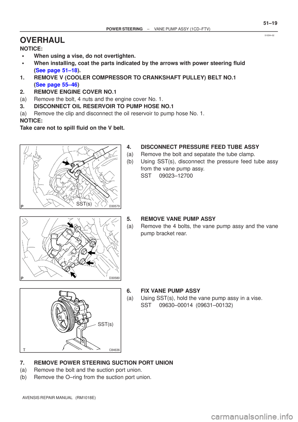
4. DISCONNECT PRESSURE FEED TUBE ASSY
(a) Remove the bolt and sepatate the tube clamp.
(b) Using SST(s), disconnect the pressure feed tube assyfrom the vane pump assy.
SST 09023±12700
5. REMOVE VANE PUMP ASSY
(a) Remove the 4 bolts, the vane pump assy and the vane pump bracket rear.
6. FIX VANE PUMP ASSY
(a) Using SST(s), hold the vane pump assy in a vise. SST 09630±00014 (09631±00132)
7. REMOVE POWER STEERING SUCTION PORT UNION
(a) Remove the bolt and the suction port union.
(b) Remove the O±ring from the suction port union.