Page 2681 of 5135
C50017
D03553
B C
A
A
A
B B �
C
C�
C69150
D09179
± AUTOMATIC TRANSMISSION / TRANSTRANSMISSION VALVE BODY ASSY (U241E)
40±49
AVENSIS REPAIR MANUAL (RM1018E)
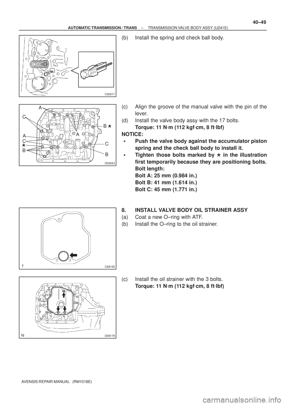
(b) Install the spring and check ball body.
(c) Align the groove of the manual valve with the pin of the
lever.
(d) Install the valve body assy with the 17 bolts.
Torque: 11 N�m (112 kgf�cm, 8 ft�lbf)
NOTICE:
�Push the valve body against the accumulator piston
spring and the check ball body to install it.
�Tighten those bolts marked by � in the illustration
first temporarily because they are positioning bolts.
Bolt length:
Bolt A: 25 mm (0.984 in.)
Bolt B: 41 mm (1.614 in.)
Bolt C: 45 mm (1.771 in.)
8. INSTALL VALVE BODY OIL STRAINER ASSY
(a) Coat a new O±ring with ATF.
(b) Install the O±ring to the oil strainer.
(c) Install the oil strainer with the 3 bolts.
Torque: 11 N�m (112 kgf�cm, 8 ft�lbf)
Page 2682 of 5135
D25591
D25674
Magnet
C83111
40±50
±
AUTOMATIC TRANSMISSION / TRANS TRANSMISSION VALVE BODY ASSY (U241E)
AVENSIS REPAIR MANUAL (RM1018E)
9. INSTALL TRANSMISSION WIRE
(a) Coat an O±ring with ATF.
(b) Install the ATF temperature sensor with the lock plate and bolt.
Torque: 6.6 N �m (67 kgf �cm, 58 in. �lbf)
(c) Connect the 5 solenoid valve connectors.
10. INSTALL AUTOMATIC TRANSAXLE OIL PAN SUB±ASSY
(a) Install the 2 magnets in the oil pan.
(b) Apply the seal packing or equivalent to the 18 bolts. Seal packing:
THREE BOND 1344 or equivalent
(c) Install a new gasket and the oil pan to the transaxle case with the 18 bolts.
Torque: 7.8 N �m (80 kgf �cm, 69 in. �lbf)
NOTICE:
Apply the seal packing or equivalent to the bolts and tight-
en them within 10 minutes after application because the
bolts should be seal bolts.
11. ADD AUTOMATIC TRANSAXLE FLUID
12.INSPECT AUTOMATIC TRANSAXLE FLUID (See page 40±2)
13. RESET MEMORY
(a)1AZ±FE (See pege 05±863)
(b)1AZ±FSE (See pege 05±920)
Page 2683 of 5135

AVENSIS REPAIR MANUAL (RM1018E)
TRANSMISSION VALVE BODY ASSY (U341E)
REPLACE")
40123±01
C62684
AT0103
D30631
D05904O±Ring
40±42
± AUTOMATIC TRANSMISSION / TRANSTRANSMISSION VALVE BODY ASSY (U341E)
AVENSIS REPAIR MANUAL (RM1018E)
TRANSMISSION VALVE BODY ASSY (U341E)
REPLACEMENT
1. REMOVE ENGINE UNDER COVER LH
2. DRAIN AUTOMATIC TRANSAXLE FLUID
(a) Remove the drain plug, gasket, and drain ATF.
(b) Install a new gasket and the drain plug.
Torque: 49 N�m (500 kgf�cm, 36 ft�lbf)
3. REMOVE AUTOMATIC TRANSAXLE OIL PAN
SUB±ASSY
(a) Remove the 19 bolts, oil pan and gasket.
NOTICE:
Some fluid will remain in the oil pan. Remove all of the pan
bolts, and carefully remove the oil pan assembly. Discard
the gasket.
(b) Remove the 2 magnets from the oil pan.
(c) Examine the particles in the oil pan.
(1) Remove the magnets and use them to collect any
steel chips. Look at the chips and particles in the oil
pan and on the magnet carefully to see the type of
wear which might be found in the tranaxle.
Steel (magnetic): bearing, gear and plate wear
Brass (non±magnetic): bearing wear
4. REMOVE VALVE BODY OIL STRAINER ASSY
(a) Remove the 3 bolts and oil strainer.
NOTICE:
Be careful as some fluid will come out with the oil strainer.
(b) Remove the O±ring from the oil strainer.
Page 2686 of 5135

40±45
AVENSIS REPAIR MANUAL (RM1018E)
(g) Tempo")
D30633
Detent
Spring
Cover
A
B
D30632
C62926
O±Ring
D30631
������C93943
Magnet
± AUTOMATIC TRANSMISSION / TRANSTRANSMISSION VALVE BODY ASSY (U341E)
40±45
AVENSIS REPAIR MANUAL (RM1018E)
(g) Temporarily install the detent spring and cover with the 2
bolts.
Bolt length:
Bolt A: 14 mm (0.55 in.)
Bolt B: 45 mm (1.77 in.)
(h) Check that the manual valve lever contacts the center of
the roller at the tip of the detent spring.
(i) Tighten the 15 bolts.
Torque: 11 N�m (110 kgf�cm, 8 ft�lbf)
(j) Install the ATF temperature sensor with the lock plate and
bolt.
Torque: 11 N�m (110 kgf�cm, 8 ft�lbf)
(k) Connect the 5 shift solenoid valve connectors.
7. INSTALL VALVE BODY OIL STRAINER ASSY
(a) Coat a new O±ring with ATF.
(b) Install the O±ring to the oil strainer.
(c) Install the oil strainer with the 3 bolts.
Torque: 11 N�m (110 kgf�cm, 8 ft�lbf)
8. INSTALL AUTOMATIC TRANSAXLE OIL PAN
SUB±ASSY
(a) Install the 2 magnets in the oil pan, as shown in the il-
lustration.
(b) Install a new gasket to the oil pan.
Page 2687 of 5135
D08009
40±46
±
AUTOMATIC TRANSMISSION / TRANS TRANSMISSION VALVE BODY ASSY(U341E)
AVENSIS REPAIR MANUAL (RM1018E)
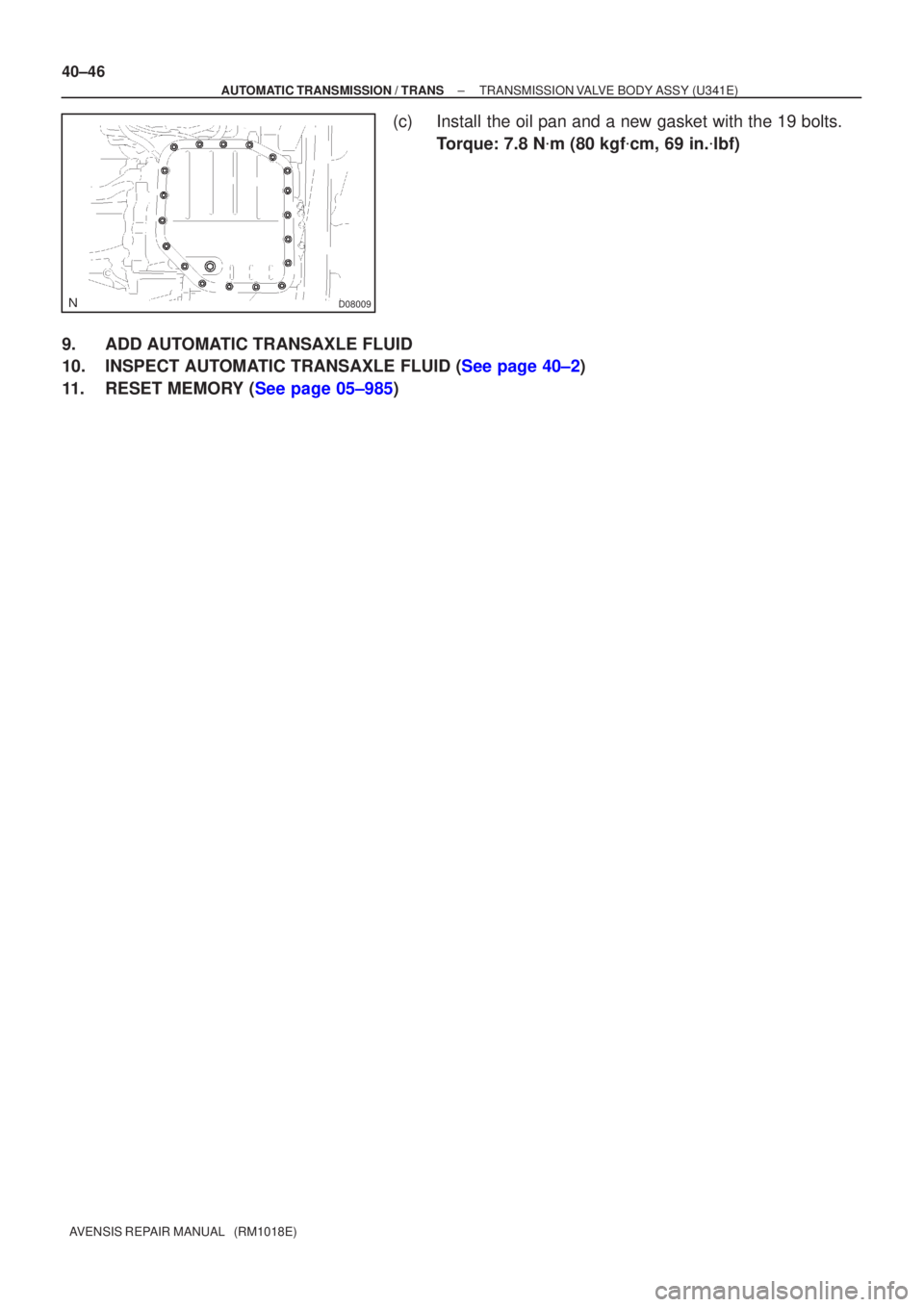
(c)Install the oil pan and a new gasket with the 19 bolts. Torque: 7.8 N �m (80 kgf �cm, 69 in. �lbf)
9.ADD AUTOMATIC TRANSAXLE FLUID
10.INSPECT AUTOMATIC TRANSAXLE FLUID (See page 40±2)
11.RESET MEMORY (See page 05±985)
Page 2692 of 5135

AVENSIS REPAIR MANUAL (RM1018E)
(d) Clean and check the oil coo")
C11090
D25368
OK NG
The Bottom is
Damaged
C81014
40±38± AUTOMATIC TRANSMISSION / TRANSTORQUE CONVERTER CLUTCH AND DRIVE
PLATE (ATM)
AVENSIS REPAIR MANUAL (RM1018E)
(d) Clean and check the oil cooler and oil pipe line.
(1) If the torque converter clutch is inspected or the ATF
is exchanged, clean the oil cooler and oil pipe line.
HINT:
�Spray compressed air of 196 kPa (2 kgf/cm2, 28 psi) from
the inlet hose.
�If plenty of fine powders are identified in the ATF, add new
ATF using a bucket pump and clean it again.
(2) If the ATF is cloudy, inspect the oil cooler.
(e) Prevent deformation of the torque converter clutch and
damage to the oil pump gear.
(1) When any marks due to interference are found on
the end of the bolt for the torque converter clutch
and on the bottom of the bolt hole, replace the bolt
and the torque converter clutch.
(2) All of the bolts shall have the same length.
(3) Do not lose the spring washer.
2. INSPECT DRIVE PLATE & RING GEAR SUB±ASSY
(a) Set up a dial indicator and measure the drive plate runout.
(b) Check the damage of the ring gear.
Maximum runout: 0.20 mm (0.0079 in.)
If the runout is not within the specification or ring gear is dam-
aged, replace the drive plate.
Page 2694 of 5135

AVENSIS REPAIR MANUAL (RM1018E)
11. SEPARATE CONNECTOR
(a) Separate the 2 wire harnesse clamps")
D30342
D30343
D30346
D30344
40±26
±
AUTOMATIC TRANSMISSION / TRANS AUTOMATIC TRANSAXLE ASSY (U241E)
AVENSIS REPAIR MANUAL (RM1018E)
11. SEPARATE CONNECTOR
(a) Separate the 2 wire harnesse clamps from the oil filler tube.
(b) Separate the transmission wire connector.
(c) Separate the park/neutral position switch connector.
(d) Separate the 2 speed sensor connectors.
12. REMOVE TRANSMISSION CONTROL CABLE CLAMP
(a) Remove the bolt and transmission control cable clamp from the automatic transaxle.
13. REMOVE TRANSMISSION OIL FILLER TUBE SUB±ASSY
(a) Remove the ATF level gauge.
(b) Remove the bolt and oil filler tube.
(c) Remove the O±ring from the oil filler tube.
14. REMOVE TRANSMISSION CONTROL CABLE BRACKET NO.1
(a) Remove the 3 bolts and control cable bracket No.1.
15. REMOVE FRONT WHEELS
16. REMOVE ENGINE UNDER COVER RH
17. REMOVE ENGINE UNDER COVER LH
18. DRAIN AUTOMATIC TRANSAXLE FLUID
(a) Remove the drain plug gasket and drain ATF.
(b) Install a new gasket and drain plug. Torque: 49 N �m (500 kgf �cm, 36 ft �lbf)
19. DRAIN COOLANT
(a)1AZ±FE (See pege 16±19)
(b)1AZ±FSE (See pege 16±31)
Page 2695 of 5135

40±27
AVENSIS REPAIR MANUAL (RM1018E)
20. SEPARATE OIL COOLER INLET TU")
D30345
D25745
No. 1 Engine HangerNo. 2 Engine Hanger
C80168
±
AUTOMATIC TRANSMISSION / TRANS AUTOMATIC TRANSAXLE ASSY (U241E)
40±27
AVENSIS REPAIR MANUAL (RM1018E)
20. SEPARATE OIL COOLER INLET TUBE NO.1
(a) Using SST, disconnect the oil cooler inlet tube No.1.
SST 09023±12700
21. SEPARATE OIL COOLER OUTLET TUBE NO.1
(a) Using SST, disconnect the oil cooler outlet tube No.1. SST 09023±12700
22. SUSPEND ENGINE ASSY
(a) Install the No.1 and No.2 engine hangers in the correctdirection.
Parts No.:
No. 1 engine hanger: 12281±28010
No. 2 engine hanger: 12282±28010
Bolt: 91512±61020
Torque: 38 N �m (387 kgf �cm, 28 ft �lbf)
(b) Attach the engine chain hoist to the engine hanger.
CAUTION:
Do not attempt to hang the engine by hooking the chain to
any other part.
23.REMOVE EXHAUST PIPE ASSY FRONT (See page 15±7)
24.REMOVE FRONT DRIVE SHAFT ASSY RH (See page 30±6)
25.REMOVE FRONT DRIVE SHAFT ASSY LH (See page 30±6) SST 09520±01010, 09520±24010 (09520±32040)
26. REMOVE STARTER ASSY
(a) Remove the nut and disconnect the starter wire.
(b) Disconnect the connector.
(c) Remove the 2 bolts and starter.
27. SUPPORT AUTOMATIC TRANSAXLE ASSY
(a) Support the automatic transaxle with a transmission jack.
28. REMOVE ENGINE MOUNTING MEMBER SUB±ASSYCENTER
(a) Remove the 4 bolts and center member with engine
mounting insulator FR.

AVENSIS REPAIR MANUAL (RM1018E)
9. INSTALL TRANSMISSION WIRE
(a) Coat an O±ring with ATF.
(")