Page 2548 of 5135

C91598
������F45254
(A)
C83851
C83155
1AZ±FSE/
1AZ±FE:
F44774
1CD±FTV: 30±18
± DRIVE SHAFT / PROPELLER SHAFTFRONT DRIVE SHAFT
AVENSIS REPAIR MANUAL (RM1018E)
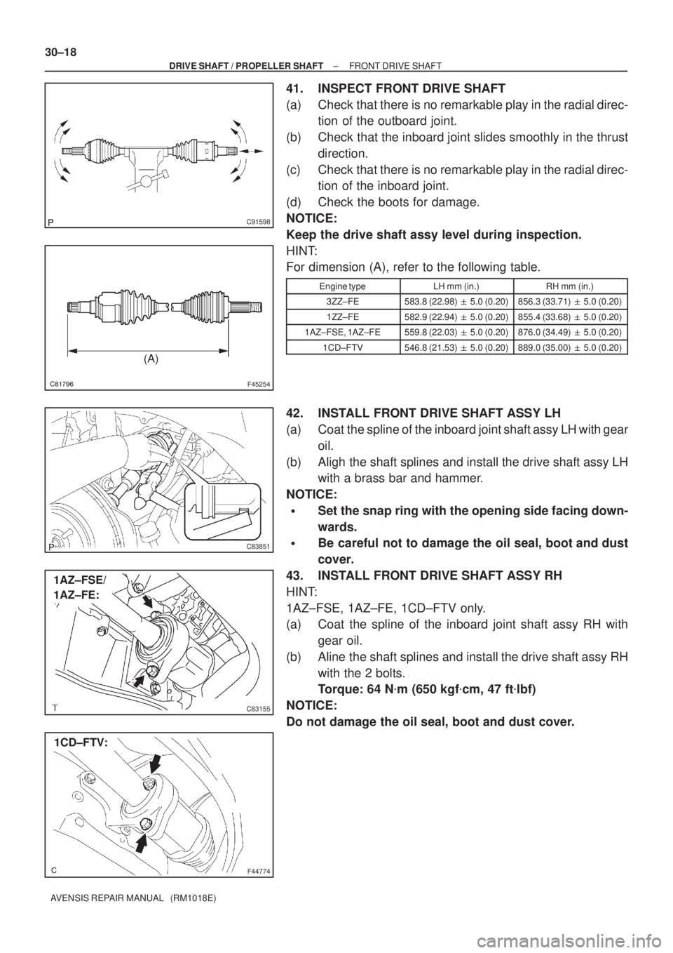
41. INSPECT FRONT DRIVE SHAFT
(a) Check that there is no remarkable play in the radial direc-
tion of the outboard joint.
(b) Check that the inboard joint slides smoothly in the thrust
direction.
(c) Check that there is no remarkable play in the radial direc-
tion of the inboard joint.
(d) Check the boots for damage.
NOTICE:
Keep the drive shaft assy level during inspection.
HINT:
For dimension (A), refer to the following table.
Engine typeLH mm (in.)RH mm (in.)
3ZZ±FE583.8 (22.98) � 5.0 (0.20)856.3 (33.71) � 5.0 (0.20)
1ZZ±FE582.9 (22.94) � 5.0 (0.20)855.4 (33.68) � 5.0 (0.20)
1AZ±FSE, 1AZ±FE559.8 (22.03) � 5.0 (0.20)876.0 (34.49) � 5.0 (0.20)
1CD±FTV546.8 (21.53) � 5.0 (0.20)889.0 (35.00) � 5.0 (0.20)
42. INSTALL FRONT DRIVE SHAFT ASSY LH
(a) Coat the spline of the inboard joint shaft assy LH with gear
oil.
(b) Aligh the shaft splines and install the drive shaft assy LH
with a brass bar and hammer.
NOTICE:
�Set the snap ring with the opening side facing down-
wards.
�Be careful not to damage the oil seal, boot and dust
cover.
43. INSTALL FRONT DRIVE SHAFT ASSY RH
HINT:
1AZ±FSE, 1AZ±FE, 1CD±FTV only.
(a) Coat the spline of the inboard joint shaft assy RH with
gear oil.
(b) Aline the shaft splines and install the drive shaft assy RH
with the 2 bolts.
Torque: 64 N�m (650 kgf�cm, 47 ft�lbf)
NOTICE:
Do not damage the oil seal, boot and dust cover.
Page 2550 of 5135

F13686
HoldTurn
C68609
30±20
±
DRIVE SHAFT / PROPELLER SHAFT FRONT DRIVE SHAFT
AVENSIS REPAIR MANUAL (RM1018E)
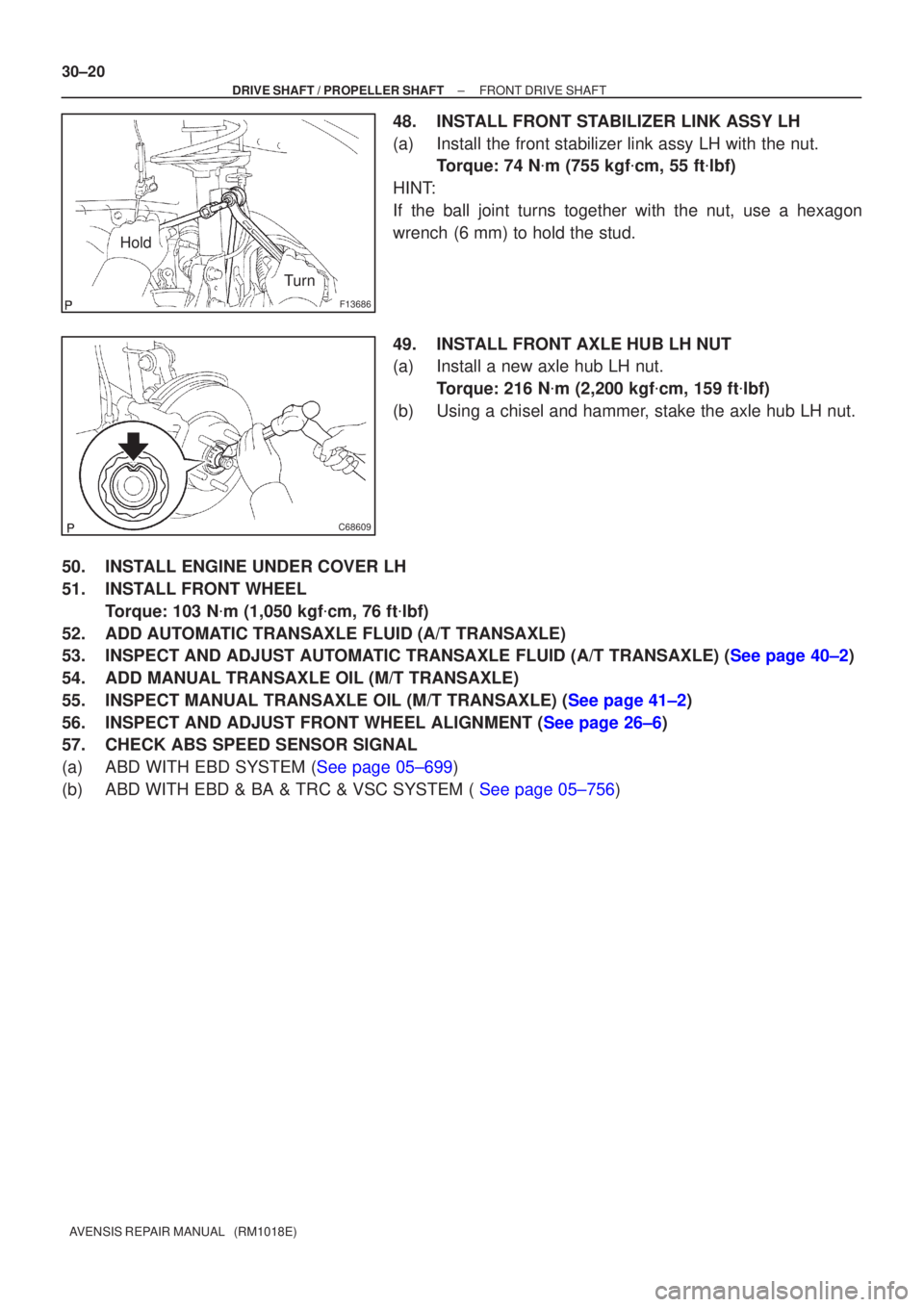
48.INSTALL FRONT STABILIZER LINK ASSY LH
(a)Install the front stabilizer link assy LH with the nut. Torque: 74 N �m (755 kgf �cm, 55 ft �lbf)
HINT:
If the ball joint turns together with the nut, use a hexagon
wrench (6 mm) to hold the stud.
49.INSTALL FRONT AXLE HUB LH NUT
(a)Install a new axle hub LH nut. Torque: 216 N �m (2,200 kgf �cm, 159 ft �lbf)
(b)Using a chisel and hammer, stake the axle hub LH nut.
50.INSTALL ENGINE UNDER COVER LH
51.INSTALL FRONT WHEEL Torque: 103 N �m (1,050 kgf �cm, 76 ft �lbf)
52.ADD AUTOMATIC TRANSAXLE FLUID (A/T TRANSAXLE)
53.INSPECT AND ADJUST AUTOMATIC TRANSAXLE FLUID (A/T TRANSAXLE) (See page 40±2)
54. ADD MANUAL TRANSAXLE OIL (M/T TRANSAXLE)
55.INSPECT MANUAL TRANSAXLE OIL (M/T TRANSAXLE) (See page 41±2)
56.INSPECT AND ADJUST FRONT WHEEL ALIGNMENT (See page 26±6)
57. CHECK ABS SPEED SENSOR SIGNAL
(a)ABD WITH EBD SYSTEM (See page 05±699)
(b)ABD WITH EBD & BA & TRC & VSC SYSTEM ( See page 05±756)
Page 2567 of 5135
G23881
G23865
G23874
G23868
G24531
± REAR SUSPENSIONREAR SUSPENSION ARM ASSY NO.1 LH
27±17
AVENSIS REPAIR MANUAL (RM1018E)
(c) Remove the bolt and nut, and separate the rear axle carri-
er sub±assy LH rear side from rear suspension arm assy
No.1 LH.
NOTICE:
When removing the bolt, hold the nut not to rotate.
(d) Remove the bolt and nut, and remove the rear shock ab-
sorber with coil spring.
NOTICE:
When removing the bolt, hold the nut not to rotate.
(e) Remove the bolt and nut, and separate the rear side rear
suspension arm assy No.1 LH.
NOTICE:
When removing the bolt, hold the nut not to rotate.
(f) Remove the 3 bolts on the front side and rear suspension
arm assy No.1 LH.
(g) Remove the nut, rear suspension arm bracket assy LH
and rear suspension support stopper.
Page 2570 of 5135
G23874
G23868
G23880
G23881
G23865
27±20
± REAR SUSPENSIONREAR SUSPENSION ARM ASSY NO.1 LH
AVENSIS REPAIR MANUAL (RM1018E)
(b) Install the rear side rear suspension arm assy No.1 LH,
and temporarily tighten bolt and nut.
NOTICE:
When installing the bolt, hold the nut not to rotate.
(c) Install the 3 bolts.
Torque: 65 N�m (663 kgf�cm, 48 ft�lbf)
(d) Install the front side rear axle carrier sub±assy LH to the
rear suspension arm assy No.1 LH, and temporarily tight-
en the nut.
(e) Install the axle carrier sub±assy LH to the rear suspension
arm assy No.1 LH, and temporarily tighten the bolt and
nut.
(f) Install the rear shock absorber with coil spring to the rear
suspension arm assy No.1 LH, and temporarily tighten
the bolt and nut.
Page 2574 of 5135
320W3±01
F45167
Engine Cover Sub±assy No.1
1ZZ±FE,3ZZ±FE Engine Type:
Wire Harness
Ignition Coil Cylinder Head
Cover Sub±assy
7.0 (71, 62 in.�lbf)
PCV Hose
N�m (kgf�cm, ft�lbf)
: Specified torquex8 w/o Washer:
w/ Washer:
11 (113, 8)
9.0 (92, 80 in.�lbf)
9.0 (92, 80 in.�lbf)
32±22
± BRAKEBRAKE BOOSTER ASSY (RHD)
AVENSIS REPAIR MANUAL (RM1018E)
COMPONENTS
Page 2595 of 5135

3201B±12
32±2
±
BRAKE BRAKE SYSTEM
AVENSIS REPAIR MANUAL (RM1018E)
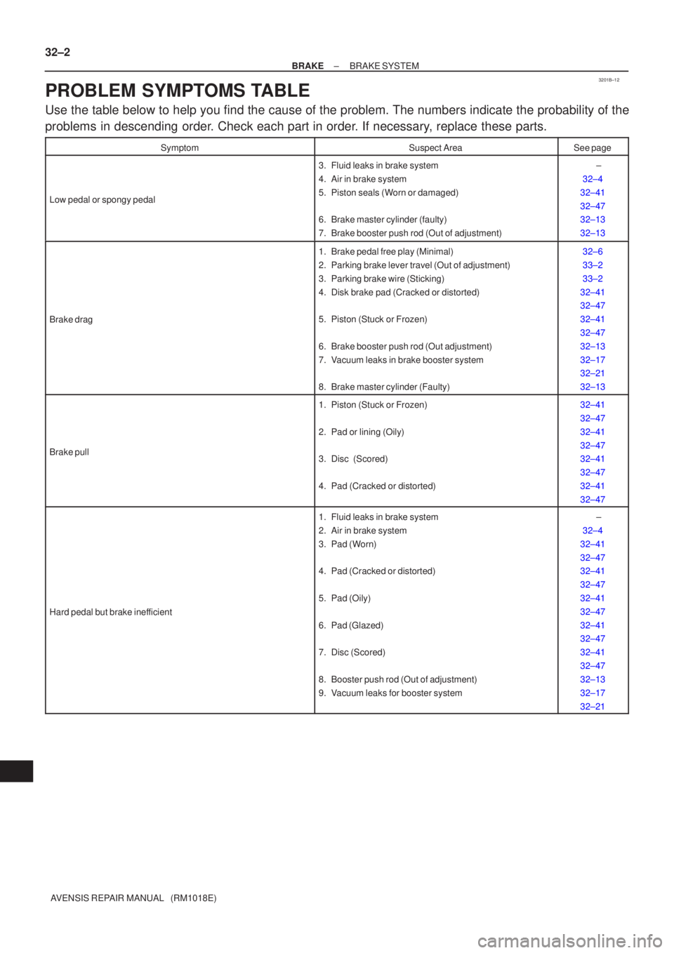
PROBLEM SYMPTOMS TABLE
Use the table below to help you find the cause of the problem. The numbers \
indicate the probability of the
problems in descending order. Check each part in order. If necessary, replace these parts.
SymptomSuspect AreaSee page
Low pedal or spongy pedal
3. Fluid leaks in brake system
4. Air in brake system
5. Piston seals (Worn or damaged)
6. Brake master cylinder (faulty)
7. Brake booster push rod (Out of adjustment) ±
32±4
32±41
32±47
32±13
32±13
Brake drag
1. Brake pedal free play (Minimal)
2. Parking brake lever travel (Out of adjustment)
3. Parking brake wire (Sticking)
4. Disk brake pad (Cracked or distorted)
5. Piston (Stuck or Frozen)
6. Brake booster push rod (Out adjustment)
7. Vacuum leaks in brake booster system
8. Brake master cylinder (Faulty)32±6
33±2
33±2
32±41
32±47
32±41
32±47
32±13
32±17
32±21
32±13
Brake pull
1. Piston (Stuck or Frozen)
2. Pad or lining (Oily)
3. Disc (Scored)
4. Pad (Cracked or distorted) 32±41
32±47
32±41
32±47
32±41
32±47
32±41
32±47
Hard pedal but brake inefficient
1. Fluid leaks in brake system
2. Air in brake system
3. Pad (Worn)
4. Pad (Cracked or distorted)
5. Pad (Oily)
6. Pad (Glazed)
7. Disc (Scored)
8. Booster push rod (Out of adjustment)
9. Vacuum leaks for booster system ±
32±4
32±41
32±47
32±41
32±47
32±41
32±47
32±41
32±47
32±41
32±47
32±13
32±17
32±21
Page 2609 of 5135
320VX±01
F42291
F42290
To
Master
Cylinder
FrontTo Master
Cylinder
Rear
To Rear
Wheel RH
To Front Wheel LHTo Front Wheel RH
To Rear
Wheel LH
F42292
± BRAKEBRAKE ACTUATOR ASSY (W/ VSC)
32±57
AVENSIS REPAIR MANUAL (RM1018E)
REPLACEMENT
1. DRAIN BRAKE FLUID
NOTICE:
Wash the brake fluid off immediately if it adheres to any painted surfaces.
2. REMOVE FRONT WHEEL RH
3. REMOVE FRONT FENDER LINER RH
4. REMOVE BRAKE ACTUATOR WITH BRACKET
(a) Release the latch of the brake actuator connector to dis-
connect the connector.
(b) Disconnect oil presser sensor connector.
(c) Using SST, disconnect the brake tubes from the brake ac-
tuator.
SST 09023±00100, 09023±38400
(d) Use tags or make a memo to identify the place to recon-
nect.
(e) Remove the nut, 2 bolts and brake actuator with bracket.
Page 2610 of 5135

F42292
F42290
To
Master
Cylinder
FrontTo Master
Cylinder
Rear
To Rear
Wheel RH
To Front Wheel LHTo Front Wheel RH
To Rear
Wheel LH
AA
A
A
BB
32±58
±
BRAKE BRAKE ACTUATOR ASSY (W/ VSC)
AVENSIS REPAIR MANUAL (RM1018E)
5. REMOVE BRAKE ACTUATOR ASSY
(a) Remove the 3 bolts and brake actuator from the brake acutuator bracket.
6. REMOVE OIL PRESSURE SENSOR
7. REMOVE SKID CONTROL ECU
(a) Disconnect the connector from the skid control ECU.
(b) Using a torx driver (T20), remove the 6 screws and the skid control EC\
U from the brake actuator.
8. INSTALL SKID CONTROL ECU
(a) Install the skid control ECU and 6 screws with a torx driver (T20).
(b) Connect the connector to the skid control ECU.
9. INSTALL OIL PRESSURE SENSOR
10. INSTALL BRAKE ACTUATOR ASSY
(a) Install the brake actuator with 3 the bolts to the brake actuator bracke\
t. Torque: 4.7 N �m (48 kgf �cm, 42 in. �lbf)
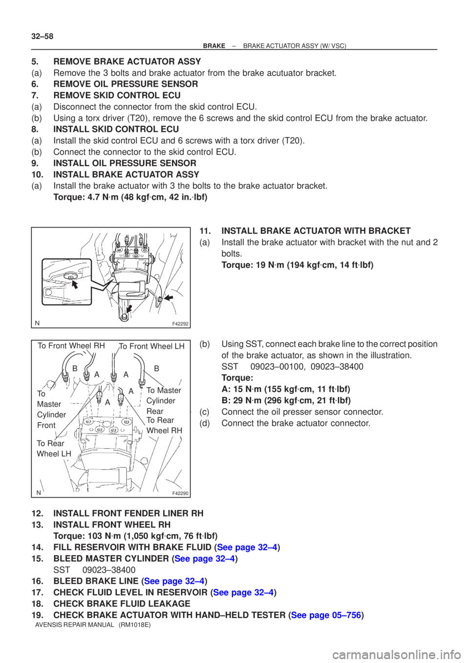
11. INSTALL BRAKE ACTUATOR WITH BRACKET
(a) Install the brake actuator with bracket with the nut and 2 bolts.
Torque: 19 N �m (194 kgf �cm, 14 ft �lbf)
(b) Using SST, connect each brake line to the correct position of the brake actuator, as shown in the illustration.
SST 09023±00100, 09023±38400
Torque:
A: 15 N �m (155 kgf �cm, 11 ft �lbf)
B: 29 N �m (296 kgf �cm, 21 ft �lbf)
(c) Connect the oil presser sensor connector.
(d) Connect the brake actuator connector.
12. INSTALL FRONT FENDER LINER RH
13. INSTALL FRONT WHEEL RH Torque: 103 N �m (1,050 kgf �cm, 76 ft �lbf)
14.FILL RESERVOIR WITH BRAKE FLUID (See page 32±4)
15.BLEED MASTER CYLINDER (See page 32±4) SST 09023±38400
16.BLEED BRAKE LINE (See page 32±4)
17.CHECK FLUID LEVEL IN RESERVOIR (See page 32±4)
18. CHECK BRAKE FLUID LEAKAGE
19.CHECK BRAKE ACTUATOR WITH HAND±HELD TESTER (See page 05±756)