Page 2650 of 5135
400D8±02
± AUTOMATIC TRANSMISSION / TRANSAUTOMATIC TRANSAXLE ASSY (ATM)
40±1
AVENSIS REPAIR MANUAL (RM1018E)
AUTOMATIC TRANSAXLE ASSY (ATM)
PRECAUTION
1. The automatic transaxle is composed of highly precision±finished parts which need careful in-
spection before reassembly because even a small nick could cause fluid leakage or affect the
performance. The instructions here are organized in order to work on only one component
group at a time. This will help avoid confusion comes from the similar±looking part of the differ-
ent sub±assemblies being on your workbench at the same time. Inspect and repair the compo-
nent groups from the converter housing side. Complete the inspection, repair and reassembly
before proceeding to the next component group. If a defect is found in a certain component
group during reassembly, inspect and repair this group immediately. If a component group can-
not be assembled because the necessary parts are being ordered, be sure to keep all the parts
of the group in a separate container while proceeding with disassembly, inspection, repair and
reassembly of the other component groups.
Recommended ATF: T±IV
2. All the disassembled parts should be washed clean and any fluid passages and holes should
be blown through with compressed air.
3. Dry all parts with compressed air. Never use shop rags to dry them.
4. Be careful of ATF or kerosene not to be squirted over your face when using compressed air.
5. The recommended automatic transaxle fluid or kerosene should be used for cleaning.
6. After cleaning, the parts should be arranged in the correct order for efficient inspection, repairs,
and reassembly.
7. When disassembling the valve body, be sure to match each valve together with the correspond-
ing spring.
8. New discs for the replacement of the brakes and clutches must be soaked in ATF for at least
15 minutes before reassembly.
9. All the oil seal rings, clutch discs, clutch plates, rotating parts, and sliding surfaces should be
coated with ATF prior to reassembly.
10. Replace all the gaskets and rubber O±rings.
11. Do not apply adhesive cements to the gaskets and similar parts.
12. Make sure that the ends of the snap ring are not aligned with one of the cutouts and are installed
in the groove correctly.
13. If a worn bushing is to be replaced, the sub±assembly containing the bushing must also be re-
placed.
14. Check the thrust bearings and races for wear or damage. Replace them as necessary.
15. Use petroleum jelly to keep the parts in place.
16. When working with FIPG material, you must follow the procedure below.
�Remove all the old packing (FIPG) material from the gasket surface using a razor blade and a
gasket scraper.
�Thoroughly clean all the components to remove all the loose material.
�Clean both the sealing surfaces with non±residue solvent.
�Parts must be reassembled within 10 minutes of application. Otherwise, the packing (FIPG) ma-
terial must be removed and reapplied.
Page 2655 of 5135
F44823
RH
LH
Front
Front
F44708
Expand
Contract 33±18
± PARKING BRAKEPARKING BRAKE ASSY
AVENSIS REPAIR MANUAL (RM1018E)
16. CHECK PARKING BRAKE INSTALLATION
(a) Check that each part is installed properly.
NOTICE:
There should be no oil or grease on the friction surface of the shoe lining and disc.
17. INSTALL REAR DISC
18. ADJUST PARKING BRAKE SHOE CLEARANCE
(a) Temporarily install the hub nuts.
(b) Remove the hole plug, and turn the adjuster and expand
the shoes until the disc locks.
(c) Contract the shoe adjuster until the disc can rotate
smoothly.
Standard : Return 8 notches
(d) Check that there is no brake drag.
(e) Install the hole plug.
19. CONNECT REAR DISC BRAKE CALIPER ASSY LH
(a) Install the rear disc brake caliper with the 2 bolts.
Torque: 47 N�m (475 kgf�cm, 34 ft�lbf)
20. INSTALL REAR WHEEL
Torque: 103 N�m (1,050 kgf�cm, 76 ft�lbf)
Page 2670 of 5135
320G5±02
F45426
F45427
F42642
±
BRAKE STEERING SENSOR
32±65
AVENSIS REPAIR MANUAL (RM1018E)
STEERING SENSOR
REPLACEMENT
1.PRECAUTION (See page 60±1)
2. REMOVE PLACE FRONT WHEELS FACING STRAIGHT AHEAD
3.DISCONNECT BATTERY NEGATIVE TERMINAL (See page 60±1)
4.REMOVE HORN BUTTON ASSY (See page 60±17)
5.REMOVE STEERING WHEEL ASSY (See page 50±9)
6.REMOVE STEERING COLUMN COVER LWR (See page 50±9)
7. REMOVE STEERING COLUMN COVER W/INSTRUMENT CLUSTER FINISH PANEL ASSY
(See page 50±9)
8.REMOVE STEERING COLUMN ASSY(See page 50±9)
9.REMOVE STEERING INTERMEDIATE SHAFT ASSY NO.2 (See page 50±9)
10. REMOVE STEERING SENSOR
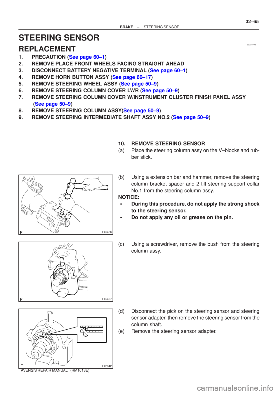
(a) Place the steering column assy on the V±blocks and rub-ber stick.
(b) Using a extension bar and hammer, remove the steering column bracket spacer and 2 tilt steering support collar
No.1 from the steering column assy.
NOTICE:
�During this procedure, do not apply the strong shock
to the steering sensor.
�Do not apply any oil or grease on the pin.
(c) Using a screwdriver, remove the bush from the steering column assy.
(d) Disconnect the pick on the steering sensor and steering sensor adapter, then remove the steering sensor from the
column shaft.
(e) Remove the steering sensor adapter.
Page 2671 of 5135
F42641
F42642
F45427
F45426
32±66
±
BRAKE STEERING SENSOR
AVENSIS REPAIR MANUAL (RM1018E)
11. INSTALL STEERING SENSOR
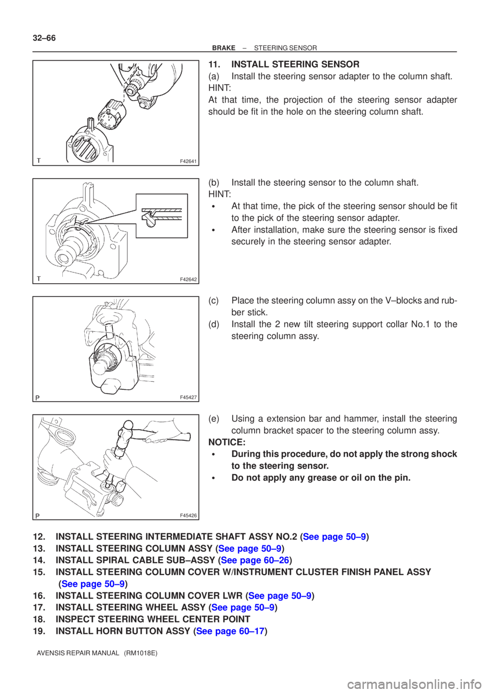
(a) Install the steering sensor adapter to the column shaft.
HINT:
At that time, the projection of the steering sensor adapter
should be fit in the hole on the steering column shaft.
(b) Install the steering sensor to the column shaft.
HINT:
�At that time, the pick of the steering sensor should be fit
to the pick of the steering sensor adapter.
�After installation, make sure the steering sensor is fixed
securely in the steering sensor adapter.
(c) Place the steering column assy on the V±blocks and rub- ber stick.
(d) Install the 2 new tilt steering support collar No.1 to the steering column assy.
(e) Using a extension bar and hammer, install the steering column bracket spacer to the steering column assy.
NOTICE:
�During this procedure, do not apply the strong shock
to the steering sensor.
�Do not apply any grease or oil on the pin.
12.INSTALL STEERING INTERMEDIATE SHAFT ASSY NO.2 (See page 50±9)
13.INSTALL STEERING COLUMN ASSY (See page 50±9)
14.INSTALL SPIRAL CABLE SUB±ASSY (See page 60±26)
15. INSTALL STEERING COLUMN COVER W/INSTRUMENT CLUSTER FINISH PANEL ASSY (See page 50±9)
16.INSTALL STEERING COLUMN COVER LWR (See page 50±9)
17.INSTALL STEERING WHEEL ASSY (See page 50±9)
18. INSPECT STEERING WHEEL CENTER POINT
19.INSTALL HORN BUTTON ASSY (See page 60±17)
Page 2675 of 5135
400DD±02
C83111
AT0103
D25591
C50009
40±52
± AUTOMATIC TRANSMISSION / TRANSTRANSMISSION WIRE (U241E)
AVENSIS REPAIR MANUAL (RM1018E)
TRANSMISSION WIRE (U241E)
REPLACEMENT
1. REMOVE ENGINE UNDER COVER LH
2. DRAIN AUTOMATIC TRANSAXLE FLUID
(a) Remove the drain plug, gasket and drain ATF.
(b) Install a new gasket and the drain plug.
Torque: 49 N�m (500 kgf�cm, 36 ft�lbf)
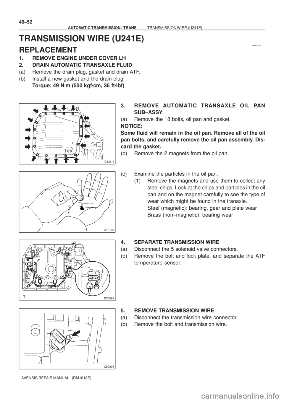
3. REMOVE AUTOMATIC TRANSAXLE OIL PAN
SUB±ASSY
(a) Remove the 18 bolts, oil pan and gasket.
NOTICE:
Some fluid will remain in the oil pan. Remove all of the oil
pan bolts, and carefully remove the oil pan assembly. Dis-
card the gasket.
(b) Remove the 2 magnets from the oil pan.
(c) Examine the particles in the oil pan.
(1) Remove the magnets and use them to collect any
steel chips. Look at the chips and particles in the oil
pan and on the magnet carefully to see the type of
wear which might be found in the tranaxle.
Steel (magnetic): bearing, gear and plate wear
Brass (non±magnetic): bearing wear
4. SEPARATE TRANSMISSION WIRE
(a) Disconnect the 5 solenoid valve connectors.
(b) Remove the bolt and lock plate, and separate the ATF
temperature sensor.
5. REMOVE TRANSMISSION WIRE
(a) Disconnect the transmission wire connector.
(b) Remove the bolt and transmission wire.
Page 2676 of 5135
D03636
C50009
D25591
D25674
Magnet
C83111
± AUTOMATIC TRANSMISSION / TRANSTRANSMISSION WIRE (U241E)
40±53
AVENSIS REPAIR MANUAL (RM1018E)
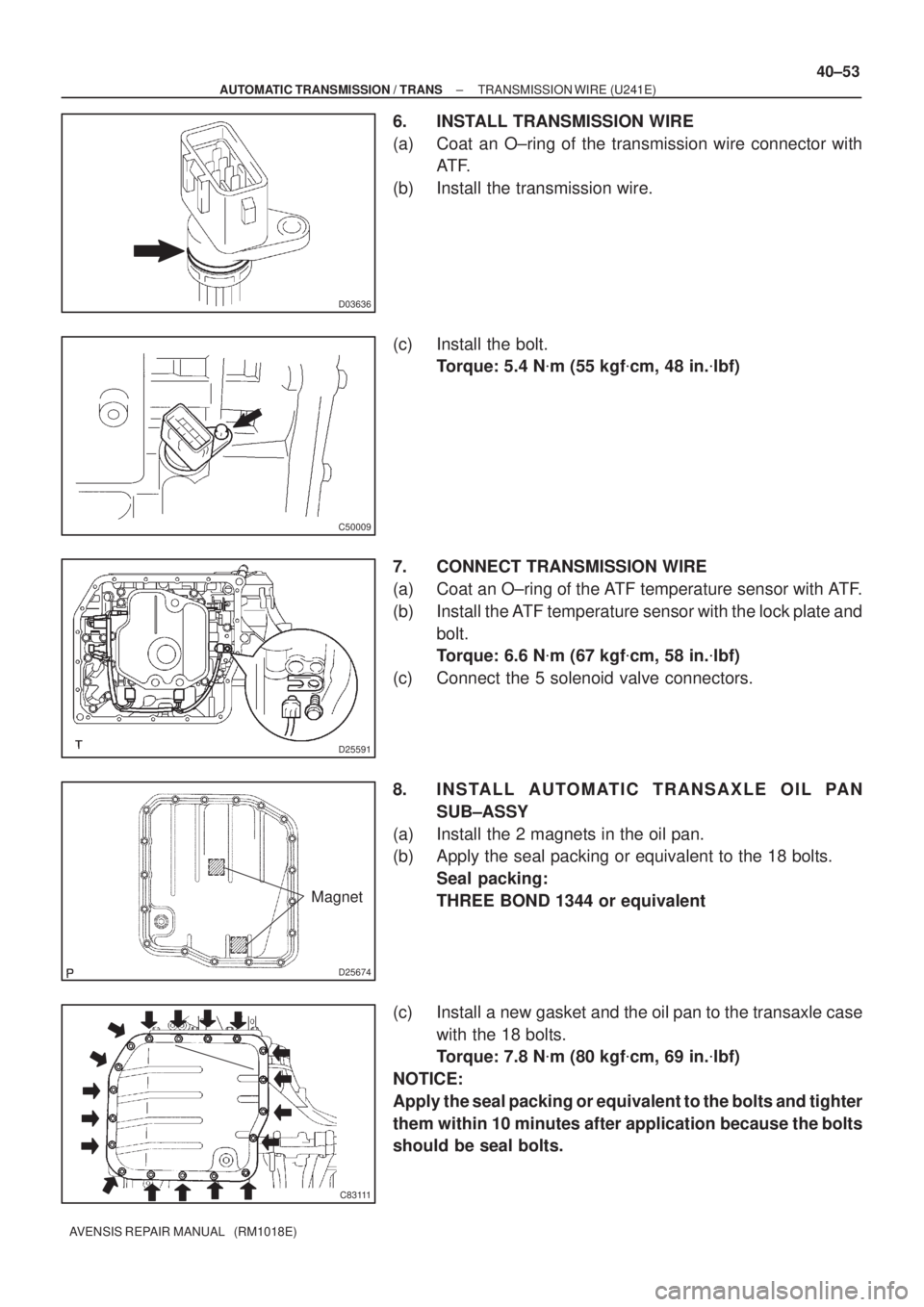
6. INSTALL TRANSMISSION WIRE
(a) Coat an O±ring of the transmission wire connector with
AT F.
(b) Install the transmission wire.
(c) Install the bolt.
Torque: 5.4 N�m (55 kgf�cm, 48 in.�lbf)
7. CONNECT TRANSMISSION WIRE
(a) Coat an O±ring of the ATF temperature sensor with ATF.
(b) Install the ATF temperature sensor with the lock plate and
bolt.
Torque: 6.6 N�m (67 kgf�cm, 58 in.�lbf)
(c) Connect the 5 solenoid valve connectors.
8. INSTALL AUTOMATIC TRANSAXLE OIL PAN
SUB±ASSY
(a) Install the 2 magnets in the oil pan.
(b) Apply the seal packing or equivalent to the 18 bolts.
Seal packing:
THREE BOND 1344 or equivalent
(c) Install a new gasket and the oil pan to the transaxle case
with the 18 bolts.
Torque: 7.8 N�m (80 kgf�cm, 69 in.�lbf)
NOTICE:
Apply the seal packing or equivalent to the bolts and tighter
them within 10 minutes after application because the bolts
should be seal bolts.
Page 2679 of 5135
400DC±02
C83111
AT0103
D25591
D09179
± AUTOMATIC TRANSMISSION / TRANSTRANSMISSION VALVE BODY ASSY (U241E)
40±47
AVENSIS REPAIR MANUAL (RM1018E)
TRANSMISSION VALVE BODY ASSY (U241E)
REPLACEMENT
1. REMOVE ENGINE UNDER COVER LH
2. DRAIN AUTOMATIC TRANSAXLE FLUID
(a) Remove the drain plug, gasket and drain ATF.
(b) Install a new gasket and the drain plug.
Torque: 49 N�m (500 kgf�cm, 36 ft�lbf)
3. REMOVE AUTOMATIC TRANSAXLE OIL PAN
SUB±ASSY
(a) Remove the 18 bolts, oil pan and gasket.
NOTICE:
Some fluid will remain in the oil pan. Remove all of the oil
pan bolts, and carefully remove the oil pan assembly. Dis-
card the gasket.
(b) Remove the 2 magnets from the oil pan.
(c) Examine the particles in the oil pan.
(1) Remove the magnets and use them to collect any
steel chips. Look at the chips and particles in the oil
pan and on the magnet carefully to see the type of
wear which might be found in the tranaxle.
Steel (magnetic): bearing, gear and plate wear
Brass (non±magnetic): bearing wear
4. SEPARATE TRANSMISSION WIRE
(a) Disconnect the 5 solenoid valve connectors.
(b) Remove the bolt and lock plate, and separate the ATF
temperature sensor.
5. REMOVE VALVE BODY OIL STRAINER ASSY
(a) Remove the 3 bolts and oil strainer.
Be careful as some fluid will come out with the oil strainer.
Page 2680 of 5135
C69150
D03553
C50017
D02938
D02938
AAB
B
B
40±48
± AUTOMATIC TRANSMISSION / TRANSTRANSMISSION VALVE BODY ASSY (U241E)
AVENSIS REPAIR MANUAL (RM1018E)
(b) Remove the O±ring from the oil strainer.
6. REMOVE TRANSMISSION VALVE BODY ASSY
(a) Support the valve body assy, and remove the 17 bolts and
the valve body assy.
NOTICE:
Be careful not to drop the check ball body and spring.
(b) Remove the check ball body and spring.
(c) Remove the 5 bolts and 5 solenoid valves.
7. INSTALL TRANSMISSION VALVE BODY ASSY
(a) Install the 5 solenoid valves with the 5 bolts.
Torque:
Bolt A: 6.6 N´m (67 kgf´cm, 58 in.�lbf)
Bolt B: 11 N´m (112 kgf´cm, 8 ft ´lbf)
Bolt length:
Bolt A: 12 mm (0.47 in.)
Bolt B: 45 mm (1.77 in.)