Page 2626 of 5135
F45419
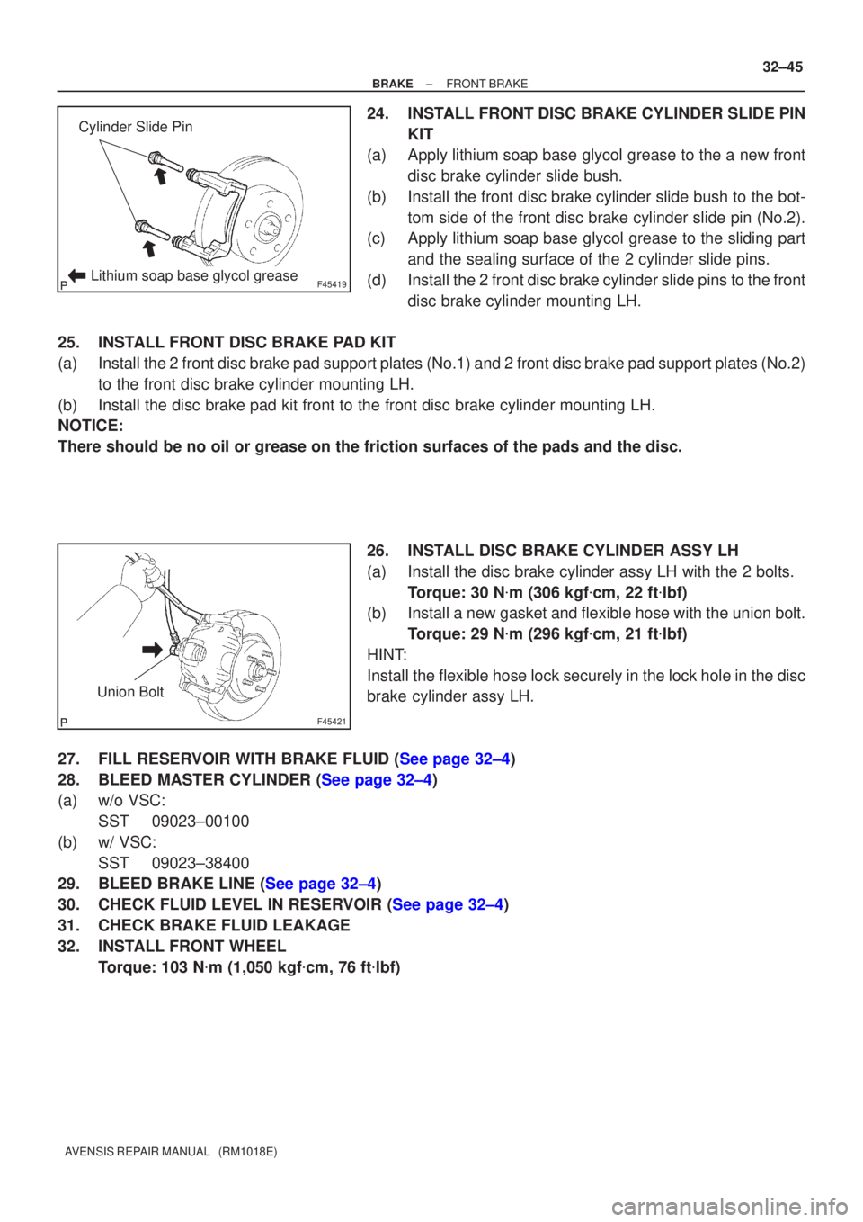
Cylinder Slide Pin
Lithium soap base glycol grease
F45421
Union Bolt
±
BRAKE FRONT BRAKE
32±45
AVENSIS REPAIR MANUAL (RM1018E)
24. INSTALL FRONT DISC BRAKE CYLINDER SLIDE PIN
KIT
(a) Apply lithium soap base glycol grease to the a new front
disc brake cylinder slide bush.
(b) Install the front disc brake cylinder slide bush to the bot- tom side of the front disc brake cylinder slide pin (No.2).
(c) Apply lithium soap base glycol grease to the sliding part
and the sealing surface of the 2 cylinder slide pins.
(d) Install the 2 front disc brake cylinder slide pins to the front disc brake cylinder mounting LH.
25. INSTALL FRONT DISC BRAKE PAD KIT
(a) Install the 2 front disc brake pad support plates (No.1) and 2 front disc bra\
ke pad support plates (No.2) to the front disc brake cylinder mounting LH.
(b) Install the disc brake pad kit front to the front disc brake cylinder mo\
unting LH.
NOTICE:
There should be no oil or grease on the friction surfaces of the pads an\
d the disc.
26. INSTALL DISC BRAKE CYLINDER ASSY LH
(a) Install the disc brake cylinder assy LH with the 2 bolts.Torque: 30 N �m (306 kgf �cm, 22 ft �lbf)
(b) Install a new gasket and flexible hose with the union bolt.
Torque: 29 N �m (296 kgf �cm, 21 ft �lbf)
HINT:
Install the flexible hose lock securely in the lock hole in the disc
brake cylinder assy LH.
27.FILL RESERVOIR WITH BRAKE FLUID (See page 32±4)
28.BLEED MASTER CYLINDER (See page 32±4)
(a) w/o VSC: SST 09023±00100
(b) w/ VSC: SST 09023±38400
29.BLEED BRAKE LINE (See page 32±4)
30.CHECK FLUID LEVEL IN RESERVOIR (See page 32±4)
31. CHECK BRAKE FLUID LEAKAGE
32. INSTALL FRONT WHEEL
Torque: 103 N �m (1,050 kgf �cm, 76 ft �lbf)
Page 2628 of 5135
320W2±01
G24251
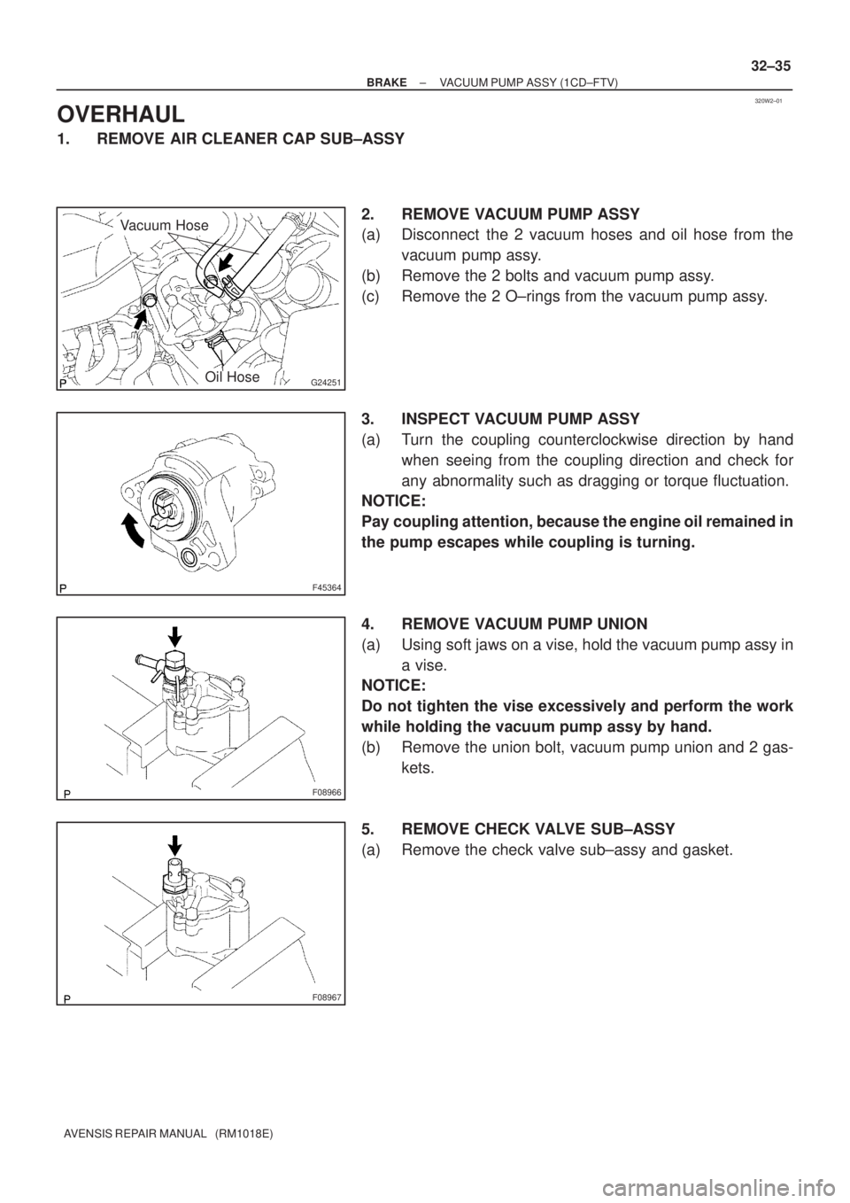
Vacuum Hose
Oil Hose
F45364
F08966
F08967
± BRAKEVACUUM PUMP ASSY (1CD±FTV)
32±35
AVENSIS REPAIR MANUAL (RM1018E)
OVERHAUL
1. REMOVE AIR CLEANER CAP SUB±ASSY
2. REMOVE VACUUM PUMP ASSY
(a) Disconnect the 2 vacuum hoses and oil hose from the
vacuum pump assy.
(b) Remove the 2 bolts and vacuum pump assy.
(c) Remove the 2 O±rings from the vacuum pump assy.
3. INSPECT VACUUM PUMP ASSY
(a) Turn the coupling counterclockwise direction by hand
when seeing from the coupling direction and check for
any abnormality such as dragging or torque fluctuation.
NOTICE:
Pay coupling attention, because the engine oil remained in
the pump escapes while coupling is turning.
4. REMOVE VACUUM PUMP UNION
(a) Using soft jaws on a vise, hold the vacuum pump assy in
a vise.
NOTICE:
Do not tighten the vise excessively and perform the work
while holding the vacuum pump assy by hand.
(b) Remove the union bolt, vacuum pump union and 2 gas-
kets.
5. REMOVE CHECK VALVE SUB±ASSY
(a) Remove the check valve sub±assy and gasket.
Page 2630 of 5135
F05383
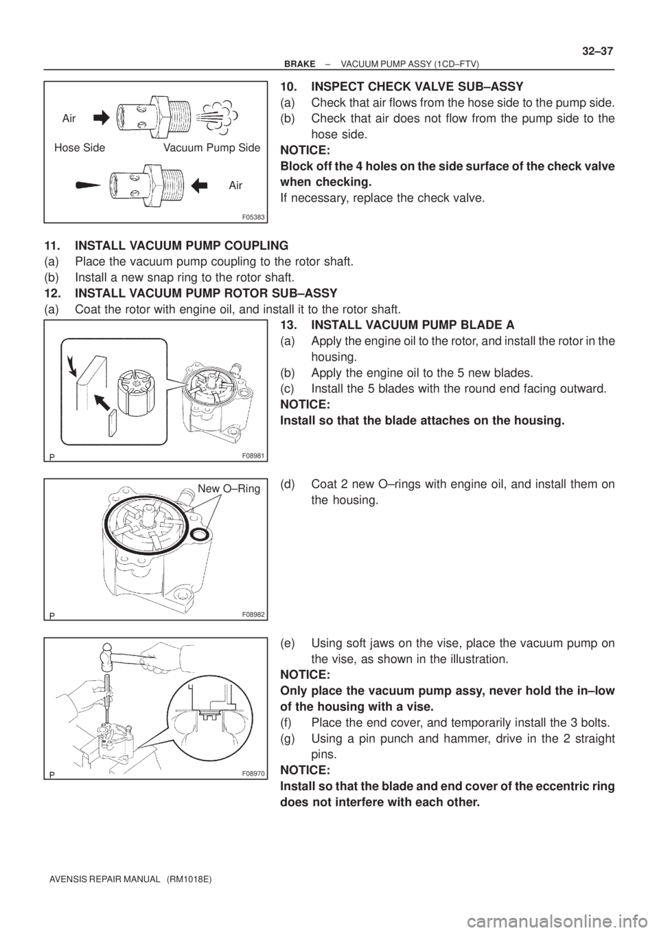
Air
Hose Side Vacuum Pump Side
Air
F08981
F08982
New O±Ring
F08970
± BRAKEVACUUM PUMP ASSY (1CD±FTV)
32±37
AVENSIS REPAIR MANUAL (RM1018E)
10. INSPECT CHECK VALVE SUB±ASSY
(a) Check that air flows from the hose side to the pump side.
(b) Check that air does not flow from the pump side to the
hose side.
NOTICE:
Block off the 4 holes on the side surface of the check valve
when checking.
If necessary, replace the check valve.
11. INSTALL VACUUM PUMP COUPLING
(a) Place the vacuum pump coupling to the rotor shaft.
(b) Install a new snap ring to the rotor shaft.
12. INSTALL VACUUM PUMP ROTOR SUB±ASSY
(a) Coat the rotor with engine oil, and install it to the rotor shaft.
13. INSTALL VACUUM PUMP BLADE A
(a) Apply the engine oil to the rotor, and install the rotor in the
housing.
(b) Apply the engine oil to the 5 new blades.
(c) Install the 5 blades with the round end facing outward.
NOTICE:
Install so that the blade attaches on the housing.
(d) Coat 2 new O±rings with engine oil, and install them on
the housing.
(e) Using soft jaws on the vise, place the vacuum pump on
the vise, as shown in the illustration.
NOTICE:
Only place the vacuum pump assy, never hold the in±low
of the housing with a vise.
(f) Place the end cover, and temporarily install the 3 bolts.
(g) Using a pin punch and hammer, drive in the 2 straight
pins.
NOTICE:
Install so that the blade and end cover of the eccentric ring
does not interfere with each other.
Page 2632 of 5135
G24250
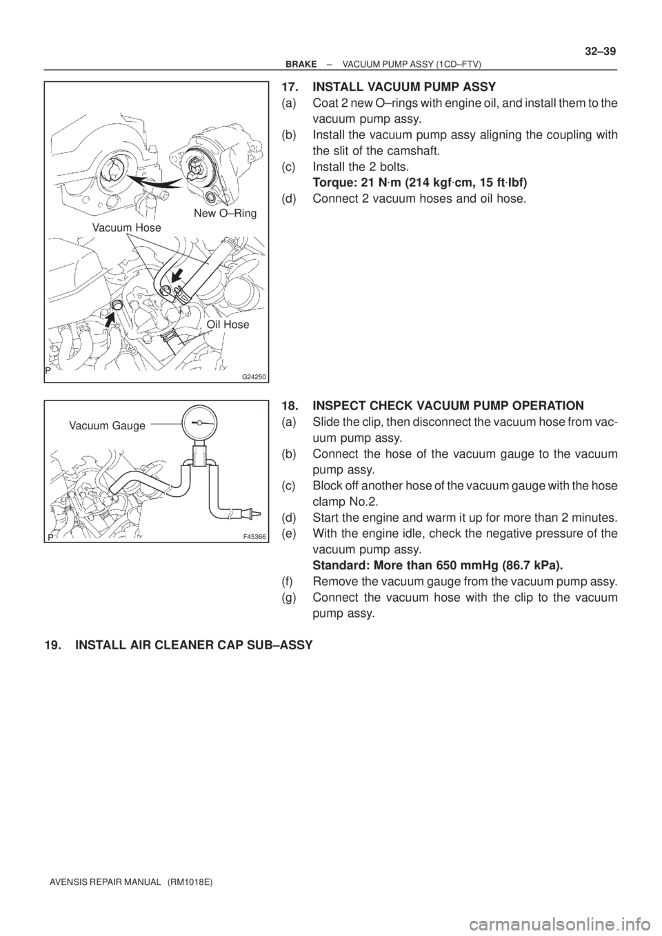
Vacuum HoseNew O±Ring
Oil Hose
F45366
Vacuum Gauge
± BRAKEVACUUM PUMP ASSY (1CD±FTV)
32±39
AVENSIS REPAIR MANUAL (RM1018E)
17. INSTALL VACUUM PUMP ASSY
(a) Coat 2 new O±rings with engine oil, and install them to the
vacuum pump assy.
(b) Install the vacuum pump assy aligning the coupling with
the slit of the camshaft.
(c) Install the 2 bolts.
Torque: 21 N�m (214 kgf�cm, 15 ft�lbf)
(d) Connect 2 vacuum hoses and oil hose.
18. INSPECT CHECK VACUUM PUMP OPERATION
(a) Slide the clip, then disconnect the vacuum hose from vac-
uum pump assy.
(b) Connect the hose of the vacuum gauge to the vacuum
pump assy.
(c) Block off another hose of the vacuum gauge with the hose
clamp No.2.
(d) Start the engine and warm it up for more than 2 minutes.
(e) With the engine idle, check the negative pressure of the
vacuum pump assy.
Standard: More than 650 mmHg (86.7 kPa).
(f) Remove the vacuum gauge from the vacuum pump assy.
(g) Connect the vacuum hose with the clip to the vacuum
pump assy.
19. INSTALL AIR CLEANER CAP SUB±ASSY
Page 2633 of 5135
32092±05
G24249
Oil Hose
Vacuum HoseO±Ring
Vacuum Pump Assy
Vacuum Hose
Check Valve Sub±assy
Vacuum Pump Union Gasket
Straight Pin
Vacuum Pump End Cover Snap Ring
CouplingVaccup Pump Housing
Vacuum pump Blade A
Straight Pin
N�m (kgf�cm, ft�lbf) : Specified torque
� Non±reusable part�
O±Ring �
�
Gasket �
Gasket � �
O±Ring �
Union bolt
7.8 (80, 69 in.�lbf)
7.8 (80, 69 in.�lbf)
7.8 (80, 69 in.�lbf)
14 (140, 10)
21 (214, 15)
21 (214, 15)
Air Cleaner Cap Sub±assy
74 (750, 54)
Connector
Vacuum pump Rotor
32±34
± BRAKEVACUUM PUMP ASSY (1CD±FTV)
AVENSIS REPAIR MANUAL (RM1018E)
COMPONENTS
Page 2635 of 5135
320W4±01
G24211
F42291
±
BRAKE BRAKE BOOSTER ASSY (RHD)
32±25
AVENSIS REPAIR MANUAL (RM1018E)
REPLACEMENT
NOTICE:
Do not adjust the brake booster push rod.
1. DRAIN BRAKE FLUID
NOTICE:
Wash the brake fluid off immediately if it adheres to any painted surface\
.
2.REMOVE BRAKE MASTER CYLINDER SUB±ASSY (See page 32±13)
(a) w/o VSC:
SST 09023±00100
(b) w/ VSC: SST 09023±38400
3.REMOVE CLUTCH MASTER CYLINDER ASSY (M/T TRANSAXLE) (See page 42±13) SST 09023±00100
4. REMOVE ENGINE ASSEMBLY WITH TRANSAXLE (1AZ±FSE ENGINE TYPE) (See page 14±204)
5. REMOVE ENGINE COVER NO.1
6.REMOVE IGNITION COIL ASSY (GASOLINE ENGINE TYPE) (See page 14±81)
7.REMOVE CYLINDER HEAD COVER SUB±ASSY (GASOLINE ENGINE TYPE) (See page 14±81)
8.REMOVE TIMING BELT NO.2 COVER (DIESEL ENGINE TYPE) (See page 14±307)
9.REMOVE CYLINDER HEAD COVER SUB±ASSY (DIESEL ENGINE TYPE) (See page 14±318)
10.REMOVE INJECTOR ASSY (DIESEL ENGINE TYPE) (See page 14±318)
11. REMOVE FRONT WHEEL RH
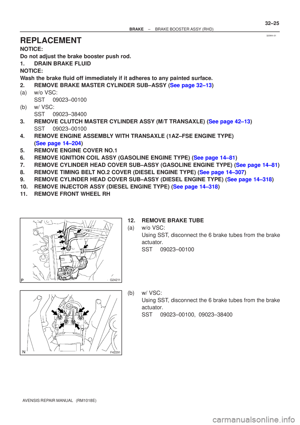
12. REMOVE BRAKE TUBE
(a) w/o VSC:Using SST, disconnect the 6 brake tubes from the brake
actuator.
SST 09023±00100
(b) w/ VSC: Using SST, disconnect the 6 brake tubes from the brake
actuator.
SST 09023±00100, 09023±38400
Page 2641 of 5135
F45057
w/o VSC:
w/ VSC:
To Master
Cylinder Rear
To
Master
Cylinder
Front
To Rear Wheel
RH
To Front Wheel LH
To Front Wheel RH
To Rear Wheel
LH
A
To
Master
Cylinder
FrontTo Master
Cylinder
Rear
To Rear
Wheel RH
To Front Wheel LHTo Front Wheel RH
To Rear
Wheel LH
AA
AA
BB
C80806
±
BRAKE BRAKE BOOSTER ASSY (RHD)
32±31
AVENSIS REPAIR MANUAL (RM1018E)
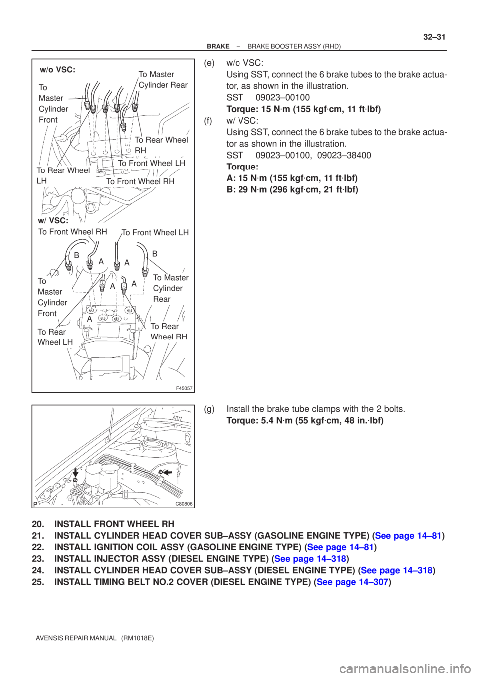
(e) w/o VSC:
Using SST, connect the 6 brake tubes to the brake actua-
tor, as shown in the illustration.
SST 09023±00100
Torque: 15 N �m (155 kgf �cm, 11 ft �lbf)
(f) w/ VSC: Using SST, connect the 6 brake tubes to the brake actua-
tor as shown in the illustration.
SST 09023±00100, 09023±38400
Torque:
A: 15 N �m (155 kgf �cm, 11 ft �lbf)
B: 29 N �m (296 kgf �cm, 21 ft �lbf)
(g) Install the brake tube clamps with the 2 bolts. Torque: 5.4 N �m (55 kgf �cm, 48 in. �lbf)
20. INSTALL FRONT WHEEL RH
21.INSTALL CYLINDER HEAD COVER SUB±ASSY (GASOLINE ENGINE TYPE) (See page 14±81)
22.INSTALL IGNITION COIL ASSY (GASOLINE ENGINE TYPE) (See page 14±81)
23.INSTALL INJECTOR ASSY (DIESEL ENGINE TYPE) (See page 14±318)
24.INSTALL CYLINDER HEAD COVER SUB±ASSY (DIESEL ENGINE TYPE) (See page 14±318)
25.INSTALL TIMING BELT NO.2 COVER (DIESEL ENGINE TYPE) (See page 14±307)
Page 2649 of 5135
400D7±02
D25120
OK if hot
Add if hot 40±2
± AUTOMATIC TRANSMISSION / TRANSAUTOMATIC TRANSAXLE FLUID (ATM)
AVENSIS REPAIR MANUAL (RM1018E)
AUTOMATIC TRANSAXLE FLUID (ATM)
ON±VEHICLE INSPECTION
1. CHECK THE FLUID LEVEL
HINT:
Drive the vehicle so that the engine and transaxle are at the nor-
mal operating temperature.
Fluid temperature: 70 ± 80 �C (158 ± 176 �F)
(a) Park the vehicle on a level surface and set the parking
brake.
(b) With the engine idling and the brake pedal depressed,
shift the shift lever into all position from P to L position and
return to P position.
(c) Pull out the dipstick and wipe it clean.
(d) Push it back fully into the pipe.
(e) Pull it out and check that the fluid level is in the HOT posi-
tion.
If there are leaks, it is necessary to repair or replace O±rings,
FIPGs, oil seals, plugs or other parts.