Page 2461 of 5135
F44616
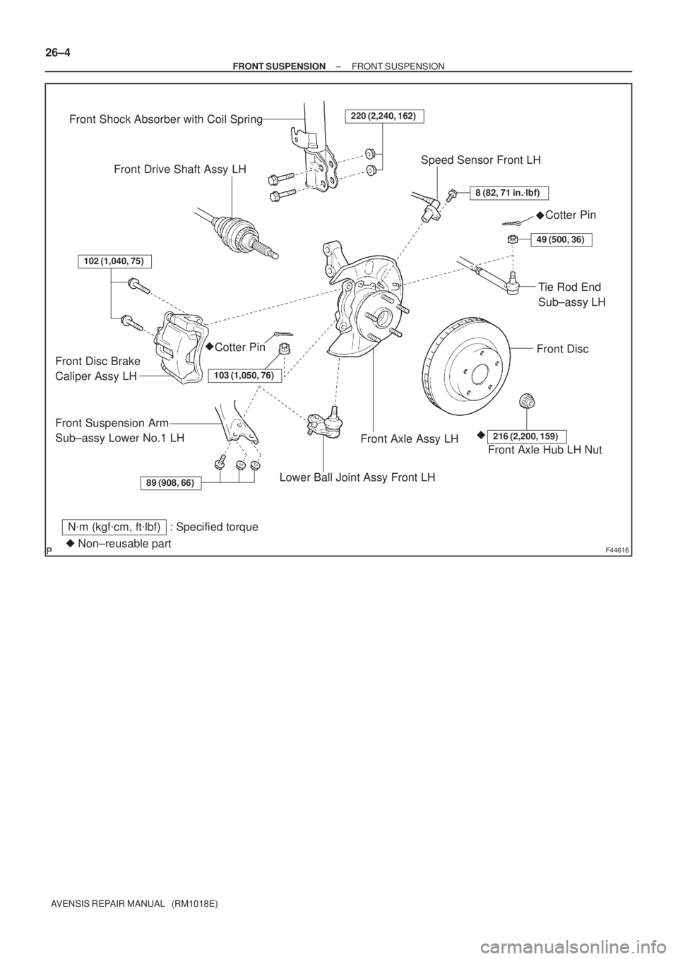
89 (908, 66)
102 (1,040, 75)
220 (2,240, 162)
8 (82, 71 in.�lbf)
49 (500, 36)
103 (1,050, 76)
216 (2,200, 159)
Front Shock Absorber with Coil Spring
Front Drive Shaft Assy LHSpeed Sensor Front LH
Cotter Pin
Front Disc
Tie Rod End
Sub±assy LH
Cotter Pin
Front Disc Brake
Caliper Assy LH
Front Suspension Arm
Sub±assy Lower No.1 LH
Lower Ball Joint Assy Front LH
Front Axle Assy LHFront Axle Hub LH Nut
N�m (kgf�cm, ft�lbf) : Specified torque
�Non±reusable part�
�� 26±4
± FRONT SUSPENSIONFRONT SUSPENSION
AVENSIS REPAIR MANUAL (RM1018E)
Page 2467 of 5135
B08263
Ohmmeter
Continuity
± STARTING & CHARGINGPRE±HEATING SYSTEM (1CD±FTV)
19±31
AVENSIS REPAIR MANUAL (RM1018E)
4. INSPECT GLOW PLUGS
(a) Using an ohmmeter, check that there is continuity be-
tween the glow plug terminal and ground.
Standard resistance: Approx. 0.72 � at 20�C (68�F)
NOTICE:
�Be careful not to damage the glow plug pipes as it
could cause an open circuit or shorten life of the glow
plugs.
�Avoid getting oil and gasoline on the glow plug when
cleaning.
�Wipe up any oil on the terminal and Bakelite washer
with a dry cloth if they are stained with oil during in-
spection.
�Be careful not to apply more than 11 V to the glow plug
as it could cause an open circuit.
Page 2474 of 5135

AVENSIS REPAIR MANUAL (RM1018E)
STARTING SYSTEM (1CD±FTV)
INSPECTIO")
190NL±01
A78633
Terminal CTerminal 50
A78634Disconnect
A78635
Disconnect
19±22
± STARTING & CHARGINGSTARTING SYSTEM (1CD±FTV)
AVENSIS REPAIR MANUAL (RM1018E)
STARTING SYSTEM (1CD±FTV)
INSPECTION
1. INSPECT STARTER ASSY
NOTICE:
These tests must be performed within 3 to 5 seconds to
avoid burning out the coil.
(a) Do pull±in test
(1) Disconnect the field coil lead wire from terminal C.
(2) Connect the battery to the magnetic switch as
shown in the illustration on the left. Check that the
clutch pinion gear is extended.
If the clutch pinion gear is not extended, replace the magnetic
switch.
(b) Do hold±in test
(1) Disconnect the negative (±) lead from the terminal
C with the above condition (a) is being maintained.
Check that the pinion gear remains extended.
If the clutch pinion gear returns, replace the magnetic switch.
(c) Inspect clutch pinion gear return
(1) Disconnect the negative (±) lead from the switch
body. Check that the clutch pinion gear returns.
If the clutch pinion gear does not return, replace the magnetic
switch.
Page 2475 of 5135
A78637
Terminal 30
Terminal 50
Ammeter
B16200
± STARTING & CHARGINGSTARTING SYSTEM (1CD±FTV)
19±23
AVENSIS REPAIR MANUAL (RM1018E)
(d) Do no±load performance test
(1) Connect the field coil lead wire to terminal C. Make
sure that the lead is not grounded.
Torque: 5.9 N�m (60 kgf�cm, 52 in�lbf)
(2) Clamp the starter in a vise.
(3) Connect the battery and an ammeter to the starter
as shown in the illustration.
(4) Check that the starter rotates smoothly and steadily
with the clutch pinion gear extended. Check that the
ammeter reads the specified current.
Specified current: 190 A or less at 11.5 V
2. INSPECT STARTER RELAY ASSY
(a) Continuity inspection.
(1) Using an ohmmeter, check for continuity between
each terminal.
Specified condition:
Terminal No.Specified condition
1 ± 2Continuity
No continuity
3 ± 5Continuity
(Apply battery voltage terminals 1 and 2)
Page 2486 of 5135

AVENSIS REPAIR MANUAL (RM1018E)
STARTING SYSTEM (1AZ±FSE)
INSPECTIO")
190NR±01
A78629
Terminal CTerminal 50
A78630Disconnect
A78631
Disconnect
19±10
± STARTING & CHARGINGSTARTING SYSTEM (1AZ±FSE)
AVENSIS REPAIR MANUAL (RM1018E)
STARTING SYSTEM (1AZ±FSE)
INSPECTION
1. INSPECT STARTER ASSY
NOTICE:
These tests must be performed within 3 to 5 seconds to
avoid burning out the coil.
(a) Do pull±in test
(1) Disconnect the field coil lead wire from terminal C.
(2) Connect the battery to the magnetic switch as
shown in the illustration on the left. Check that the
clutch pinion gear is extended.
If the clutch pinion gear is not extended, replace the magnetic
switch.
(b) Do hold±in test
(1) Disconnect the negative (±) lead from terminal C
with the above condition (a) is being maintained.
Check that the pinion gear remains extended.
If the clutch pinion gear returns, replace the magnetic switch.
(c) Inspect clutch pinion gear return
(1) Disconnect the negative (±) lead from the switch
body. Check that the clutch pinion gear returns.
If the clutch pinion gear does not return, replace the magnetic
switch.
Page 2487 of 5135
A78632
Terminal 30
Terminal 50
Ammeter
B16200
± STARTING & CHARGINGSTARTING SYSTEM (1AZ±FSE)
19±11
AVENSIS REPAIR MANUAL (RM1018E)
(d) Do no±load performance test
(1) Connect the field coil lead wire to terminal C. Make
sure that the lead is not grounded.
Torque: 5.9 N�m (60 kgf�cm, 52 in�lbf)
(2) Clamp the starter in a vise.
(3) Connect the battery and an ammeter to the starter
as shown in the illustration.
(4) Check that the starter rotates smoothly and steadily
with the clutch pinion gear extended. Check that the
ammeter reads the specified current.
Specified current:
1.3kw 85 A or less at 11.5 V
1.6kw 75 A or less at 11.5 V
2. INSPECT STARTER RELAY ASSY
(a) Continuity inspection.
(1) Using an ohmmeter, check for continuity between
each terminal.
Specified condition:
Terminal No.Specified condition
1 ± 2Continuity
No continuity
3 ± 5Continuity
(Applying battery voltage terminals 1 and 2)
Page 2488 of 5135

AVENSIS REPAIR MANUAL (RM1018E)
STARTING SYSTEM (1AZ±FE)
INSPECTION
1")
190NU±01
A78629
Terminal CTerminal 50
A78630Disconnect
A78631
Disconnect
19±8
± STARTING & CHARGINGSTARTING SYSTEM (1AZ±FE)
AVENSIS REPAIR MANUAL (RM1018E)
STARTING SYSTEM (1AZ±FE)
INSPECTION
1. INSPECT STARTER ASSY
NOTICE:
These tests must be performed within 3 to 5 seconds to
avoid burning out the coil.
(a) Do pull±in test
(1) Disconnect the field coil lead wire from terminal C.
(2) Connect the battery to the magnetic switch as
shown in the illustration on the left. Check that the
clutch pinion gear is extended.
If the clutch pinion gear is not extended, replace the magnetic
switch.
(b) Do hold±in test
(1) Disconnect the negative (±) lead from terminal C
with the above condition (a) is being maintained.
Check that the pinion gear remains extended.
If the clutch pinion gear returns, replace the magnetic switch.
(c) Inspect clutch pinion gear return
(1) Disconnect the negative (±) lead from the switch
body. Check that the clutch pinion gear returns.
If the clutch pinion gear does not return, replace the magnetic
switch.
Page 2489 of 5135
A78632
Terminal 30
Terminal 50
Ammeter
B16200
± STARTING & CHARGINGSTARTING SYSTEM (1AZ±FE)
19±9
AVENSIS REPAIR MANUAL (RM1018E)
(d) Do no±load performance test
(1) Connect the field coil lead wire to terminal C. Make
sure that the lead is not grounded.
Torque: 5.9 N�m (60 kgf�cm, 52 in�lbf)
(2) Clamp the starter in a vise.
(3) Connect the battery and an ammeter to the starter
as shown in the illustration.
(4) Check that the starter rotates smoothly and steadily
with the clutch pinion gear extended. Check that the
ammeter reads the specified current.
Specified current: 85 A or less at 11.5 V
2. INSPECT STARTER RELAY ASSY
(a) Continuity inspection.
(1) Using an ohmmeter, check for continuity between
each terminal.
Specified condition:
Terminal No.Specified condition
1 ± 2Continuity
No continuity
3 ± 5Continuity
(Apply battery voltage terminals 1 and 2)

19±31
AVENSIS REPAIR MANUAL (RM1018E)
4. INSPECT GLOW PLUGS
(a) Using an ohmmeter, check that there is continuity be-")

19±23
AVENSIS REPAIR MANUAL (RM1018E)
(d) Do no±load performance test
(1) Connect the field coil lea")

19±11
AVENSIS REPAIR MANUAL (RM1018E)
(d) Do no±load performance test
(1) Connect the field coil lea")

19±9
AVENSIS REPAIR MANUAL (RM1018E)
(d) Do no±load performance test
(1) Connect the field coil lead")