Page 2425 of 5135
Adhesive
A50082
17±2
± LUBRICATIONLUBRICATION SYSTEM (1ZZ±FE/3ZZ±FE)
AVENSIS REPAIR MANUAL (RM1018E)
6. CHECK OIL PRESSURE
Oil pressure:
At idle29 kPa (0.3 kgf/cm2, 4.3 psi) or more
At 3,000 rpm294 to 539 kPa (3.0 to 5.5 kgf/cm2, 43 to 78 psi) or more
7. REMOVE OIL PRESSURE GAUGE
8. INSTALL OIL PRESSURE SWITCH ASSY
(a) Apply adhesive to 2 or 3 threads of the oil pressure switch.
Adhesive:
Part No. 08833±00080, THREE BOND 1344,
LOCTITE 242 or equivalent
(b) Using a 24mm deep socket wrench, install the oil pres-
sure switch.
Torque: 15 N�m (153 kgf�cm, 11 ft�lbf)
NOTICE:
Do not start the engine within 1 hour of installation.
(c) Connect the oil pressure switch connector.
9. START ENGINE AND CHECK FOR LEAKS
Page 2428 of 5135
160ME±01
A79148
SST
16±46
±
COOLING WATER PUMP ASSY(1CD±FTV)
AVENSIS REPAIR MANUAL (RM1018E)
WATER PUMP ASSY(1CD±FTV)
REPLACEMENT
1.REMOVE RADIATOR SUPPORT OPENING COVER
2.REMOVE ENGINE ROOM COVER SIDE
3.DRAIN ENGINE COOLANT(See page 16±44)
4.REMOVE FRONT WHEEL RH
5.REMOVE ENGINE UNDER COVER SUB±ASSY NO.1
6.REMOVE ENGINE UNDER COVER RH
7.REMOVE ENGINE COVER NO.1
(a)Remove the 5 nuts and the engine cover.
8.REMOVE INJECTOR DRIVER (See page 14±286)
9.REMOVE V (COOLER COMPRESSOR TO CRANKSHAFT PULLEY) BELT NO.1 (See page 14±269)
10.REMOVE GENERATOR V BELT (See page 14±269)
11.SEPARATE POWER STEERING IDLE PULLEY BRACKET (See page 14±286)
12.SEPARATE ENGINE MOUNTING INSULATOR SUB±ASSY RH(See page 14±307)
13.REMOVE CRANKSHAFT PULLEY(See page 14±307) SST 09213±54015 (90105±08076), 09330±00021, 09950±50013 (0995\
1±05010, 09952±05010, 09953±05020, 09954±05031)
14. REMOVE IDLER PULLEY SUB±ASSY
(a) Remove the bolt, the washer and the pulley.
15.REMOVE TIMING BELT NO.2 COVER(See page 14±307)
16.REMOVE TIMING BELT NO.1 COVER(See page 14±307)
17. REMOVE TIMING BELT GUIDE
18.REMOVE TRANSVERSE ENGINE ENGINE MOUNTING BRACKET(See page 14±307)
19.SET NO. 1 CYLINDER TO TDC/COMPRESSION(See page 14±307)
20.REMOVE TIMING CHAIN COVER PLATE(See page 14±307)
21.REMOVE TIMING BELT(See page 14±307)
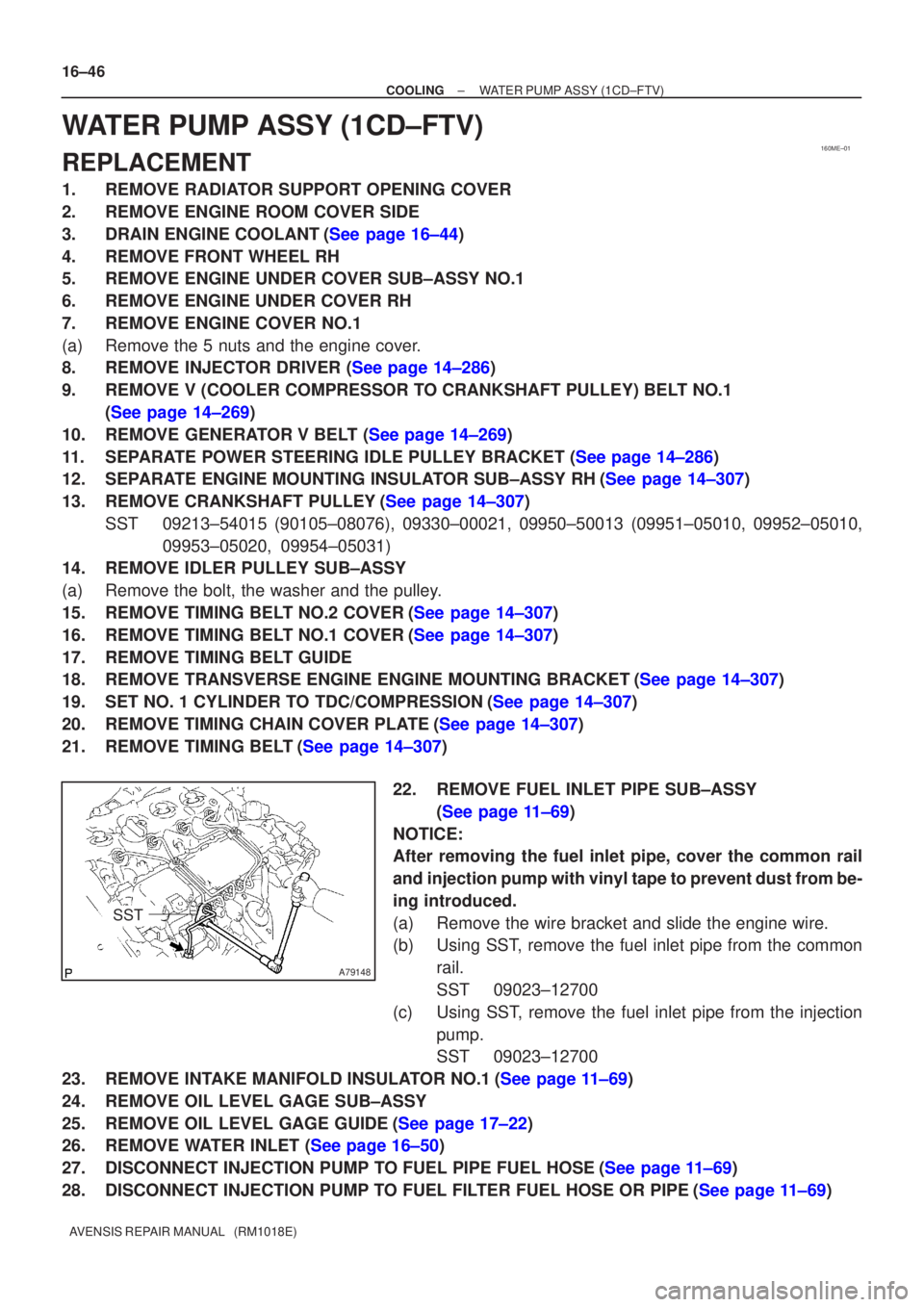
22. REMOVE FUEL INLET PIPE SUB±ASSY(See page 11±69)
NOTICE:
After removing the fuel inlet pipe, cover the common rail
and injection pump with vinyl tape to prevent dust from be-
ing introduced.
(a) Remove the wire bracket and slide the engine wire.
(b) Using SST, remove the fuel inlet pipe from the common rail.
SST 09023±12700
(c) Using SST, remove the fuel inlet pipe from the injection pump.
SST 09023±12700
23.REMOVE INTAKE MANIFOLD INSULATOR NO.1(See page 11±69)
24. REMOVE OIL LEVEL GAGE SUB±ASSY
25.REMOVE OIL LEVEL GAGE GUIDE(See page 17±22)
26.REMOVE WATER INLET (See page 16±50)
27.DISCONNECT INJECTION PUMP TO FUEL PIPE FUEL HOSE(See page 11±69)
28.DISCONNECT INJECTION PUMP TO FUEL FILTER FUEL HOSE OR PIPE(See page 11±69)
Page 2429 of 5135
A09580
8 mm
Hexagon
Wrench
A79170
A79170
A09581
8 mm
Hexagon
Wrench
Plate Washer
±
COOLING WATER PUMP ASSY(1CD±FTV)
16±47
AVENSIS REPAIR MANUAL (RM1018E)
29.REMOVE INJECTION PUMP DRIVE PULLEY(See page 11±69)
SST09960±10010 (09962±01000, 09963±01000), 09950±50013 (0995\
1±05010, 09952±05010, 09953±05020, 09954±05021)
30.REMOVE INJECTION OR SUPPLY PUMP ASSY(See page 11±69)
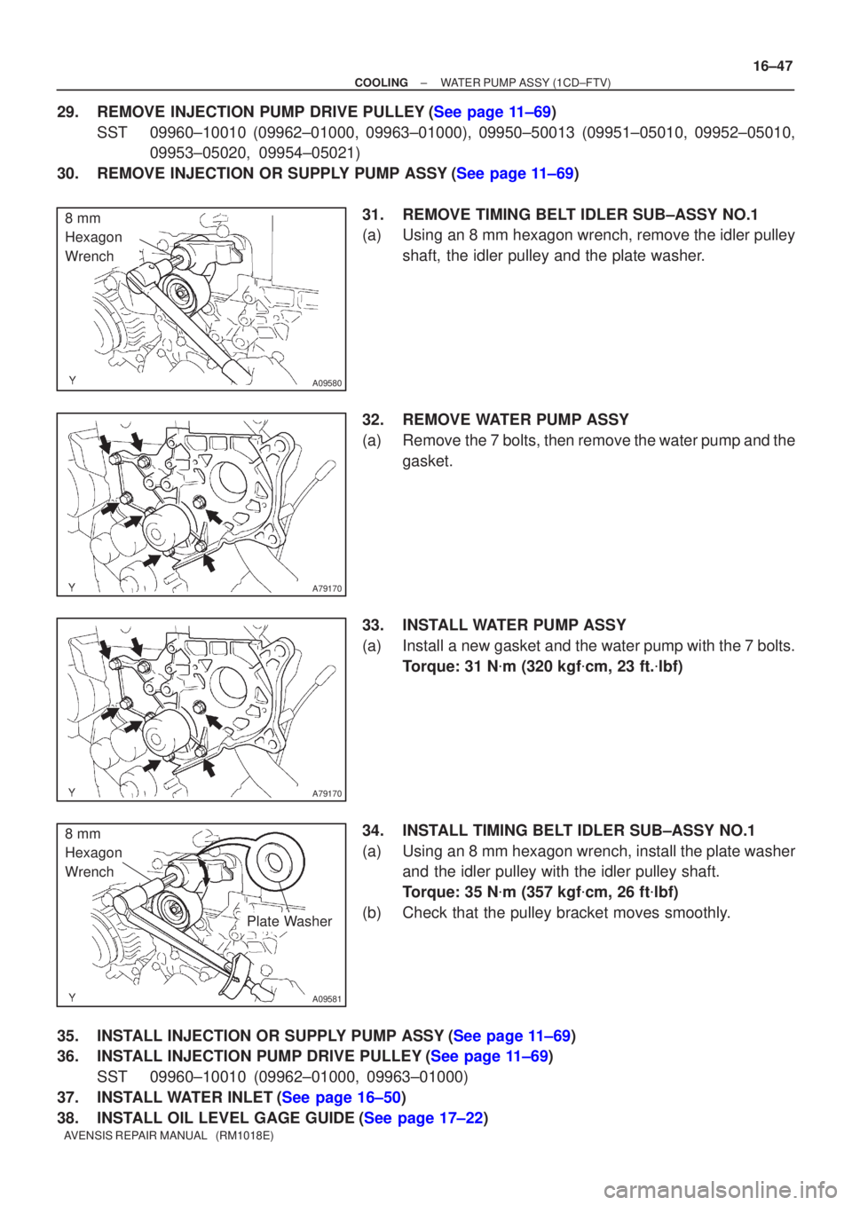
31.REMOVE TIMING BELT IDLER SUB±ASSY NO.1
(a)Using an 8 mm hexagon wrench, remove the idler pulleyshaft, the idler pulley and the plate washer.
32.REMOVE WATER PUMP ASSY
(a)Remove the 7 bolts, then remove the water pump and the gasket.
33.INSTALL WATER PUMP ASSY
(a)Install a new gasket and the water pump with the 7 bolts. Torque: 31 N �m (320 kgf �cm, 23 ft. �lbf)
34.INSTALL TIMING BELT IDLER SUB±ASSY NO.1
(a)Using an 8 mm hexagon wrench, install the plate washer and the idler pulley with the idler pulley shaft.
Torque: 35 N �m (357 kgf �cm, 26 ft �lbf)
(b)Check that the pulley bracket moves smoothly.
35.INSTALL INJECTION OR SUPPLY PUMP ASSY(See page 11±69)
36.INSTALL INJECTION PUMP DRIVE PULLEY(See page 11±69) SST 09960±10010 (09962±01000, 09963±01000)
37.INSTALL WATER INLET(See page 16±50)
38.INSTALL OIL LEVEL GAGE GUIDE(See page 17±22)
Page 2437 of 5135
190NO±01
A82615Terminal CTerminal 50
A82616Terminal C Terminal 50
A82617
Terminal C Terminal 50
± STARTING & CHARGINGSTARTING SYSTEM (1ZZ±FE/3ZZ±FE)
19±1
AVENSIS REPAIR MANUAL (RM1018E)
STARTING SYSTEM (1ZZ±FE/3ZZ±FE)
INSPECTION
1. INSPECT STARTER ASSY
NOTICE:
These tests must be performed within 3 to 5 seconds to
avoid burning out the coil.
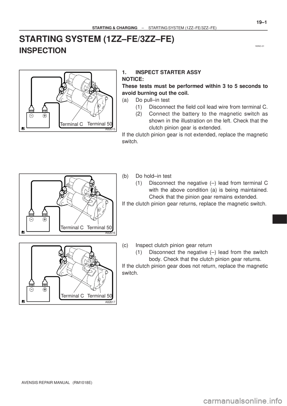
(a) Do pull±in test
(1) Disconnect the field coil lead wire from terminal C.
(2) Connect the battery to the magnetic switch as
shown in the illustration on the left. Check that the
clutch pinion gear is extended.
If the clutch pinion gear is not extended, replace the magnetic
switch.
(b) Do hold±in test
(1) Disconnect the negative (±) lead from terminal C
with the above condition (a) is being maintained.
Check that the pinion gear remains extended.
If the clutch pinion gear returns, replace the magnetic switch.
(c) Inspect clutch pinion gear return
(1) Disconnect the negative (±) lead from the switch
body. Check that the clutch pinion gear returns.
If the clutch pinion gear does not return, replace the magnetic
switch.
Page 2438 of 5135
A82618Terminal C Terminal 50
B16200
19±2
± STARTING & CHARGINGSTARTING SYSTEM (1ZZ±FE/3ZZ±FE)
AVENSIS REPAIR MANUAL (RM1018E)
(d) Do no±load performance test
(1) Connect the field coil lead wire to terminal C. Make
sure that the lead is not grounded.
Torque: 5.9 N�m (60 kgf�cm, 52 in�lbf)
(2) Clamp the starter in a vise.
(3) Connect the battery and an ammeter to the starter
as shown in the illustration.
(4) Check that the starter rotates smoothly and steadily
with the clutch pinion gear extended. Check that the
ammeter reads the specified current.
Specified current: 85 A or less at 11.5 V
2. INSPECT STARTER RELAY ASSY
(a) Continuity inspection.
(1) Using an ohmmeter, check for continuity between
each terminal.
Specified condition:
Terminal No.Specified condition
1 ± 2Continuity
No continuIty
3 ± 5Continuity
(Apply battery voltage terminals 1 and 2)
Page 2439 of 5135
1807L±01
A77896
(a)(b)
(c)
(d)
±
IGNITION CRANKSHAFT POSITION
SENSOR(1AZ±FE/1AZ±FSE)18±17
AVENSIS REPAIR MANUAL (RM1018E)
CRANKSHAFT POSITION SENSOR(1AZ±FE/1AZ±FSE)
REPLACEMENT
1.REMOVE ENGINE UNDER COVER LH (See page 19±20)
2.REMOVE ENGINE UNDER COVER RH (See page 19±20)
3.REMOVE RADIATOR SUPPORT OPENING COVER (See page 10±26)
4.REMOVE ENGINE ROOM COVER SIDE (See page 10±26)
5.REMOVE FAN AND GENERATOR V BELT
6.REMOVE GENERATOR ASSY (See page 19±20)
SST09249±63010
HINT:
�1AZ±FE: 14±105
�1AZ±FSE: 14±185
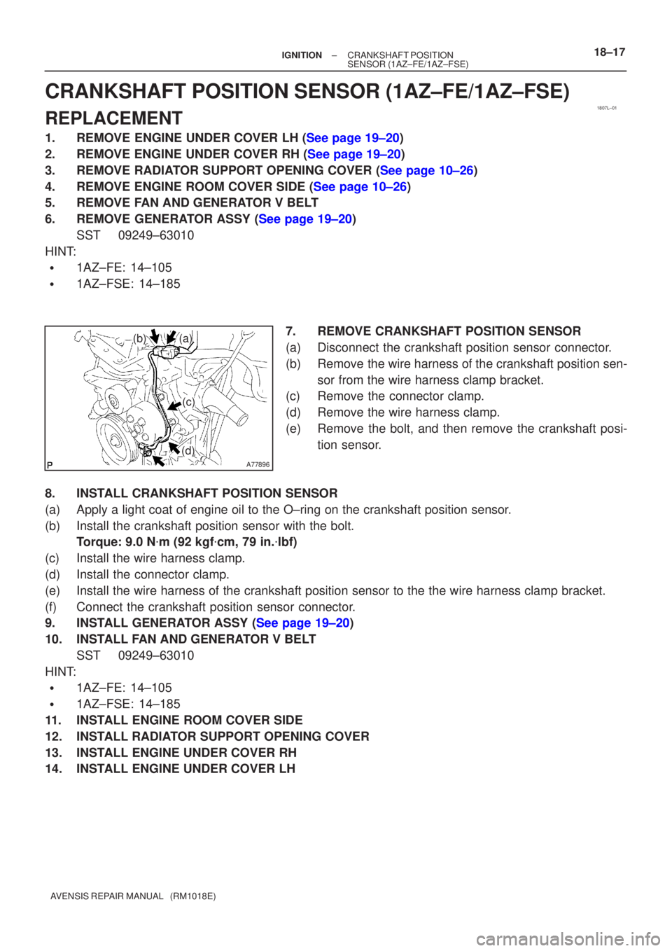
7.REMOVE CRANKSHAFT POSITION SENSOR
(a)Disconnect the crankshaft position sensor connector.
(b)Remove the wire harness of the crankshaft position sen-sor from the wire harness clamp bracket.
(c)Remove the connector clamp.
(d)Remove the wire harness clamp.
(e)Remove the bolt, and then remove the crankshaft posi-
tion sensor.
8.INSTALL CRANKSHAFT POSITION SENSOR
(a)Apply a light coat of engine oil to the O±ring on the crankshaft posi\
tion sensor.
(b)Install the crankshaft position sensor with the bolt. Torque: 9.0 N �m (92 kgf �cm, 79 in. �lbf)
(c)Install the wire harness clamp.
(d)Install the connector clamp.
(e)Install the wire harness of the crankshaft position sensor to the the wi\
re harness clamp bracket.
(f)Connect the crankshaft position sensor connector.
9.INSTALL GENERATOR ASSY (See page 19±20)
10. INSTALL FAN AND GENERATOR V BELT SST 09249±63010
HINT:
�1AZ±FE: 14±105
�1AZ±FSE: 14±185
11. INSTALL ENGINE ROOM COVER SIDE
12. INSTALL RADIATOR SUPPORT OPENING COVER
13. INSTALL ENGINE UNDER COVER RH
14. INSTALL ENGINE UNDER COVER LH
Page 2440 of 5135
1807K±01
A77895
18±16
±
IGNITION CAMSHAFT POSITION SENSOR(1AZ±FE/1AZ±FSE)
AVENSIS REPAIR MANUAL (RM1018E)
CAMSHAFT POSITION SENSOR(1AZ±FE/1AZ±FSE)
REPLACEMENT
1.REMOVE RADIATOR SUPPORT OPENING COVER (See page 10±26) 2. REMOVE CAMSHAFT POSITION SENSOR
(a) Disconnect the camshaft position sensor connector.
(b) Remove the bolt, and then remove the camshaft positionsensor.
3. INSTALL CAMSHAFT POSITION SENSOR
(a) Apply a light coat of engine oil to the O±ring on the camshaft positi\
on sensor.
(b) Install the camshaft position sensor with the bolt. Torque: 9.0 N �m (92 kgf �cm, 79 in. �lbf)
(c) Connect the camshaft position sensor connector.
4. INSTALL RADIATOR SUPPORT OPENING COVER
Page 2442 of 5135
A78640
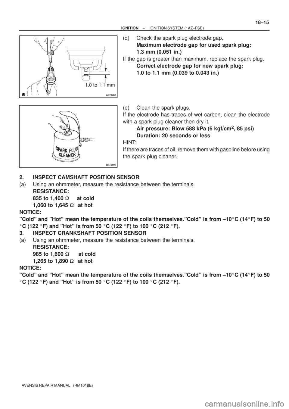
1.0 to 1.1 mm
B62019
± IGNITIONIGNITION SYSTEM (1AZ±FSE)
18±15
AVENSIS REPAIR MANUAL (RM1018E)
(d) Check the spark plug electrode gap.
Maximum electrode gap for used spark plug:
1.3 mm (0.051 in.)
If the gap is greater than maximum, replace the spark plug.
Correct electrode gap for new spark plug:
1.0 to 1.1 mm (0.039 to 0.043 in.)
(e) Clean the spark plugs.
If the electrode has traces of wet carbon, clean the electrode
with a spark plug cleaner then dry it.
Air pressure: Blow 588 kPa (6 kgf/cm
2, 85 psi)
Duration: 20 seconds or less
HINT:
If there are traces of oil, remove them with gasoline before using
the spark plug cleaner.
2. INSPECT CAMSHAFT POSITION SENSOR
(a) Using an ohmmeter, measure the resistance between the terminals.
RESISTANCE:
835 to 1,400 � at cold
1,060 to 1,645 �at hot
NOTICE:
ºColdº and ºHotº mean the temperature of the coils themselves.ºColdº is from ±10�C (14�F) to 50
�C (122 �F) and ºHotº is from 50 �C (122 �F) to 100 �C (212 �F).
3. INSPECT CRANKSHAFT POSITION SENSOR
(a) Using an ohmmeter, measure the resistance between the terminals.
RESISTANCE:
985 to 1,600 � at cold
1,265 to 1,890 �at hot
NOTICE:
ºColdº and ºHotº mean the temperature of the coils themselves.ºColdº is from ±10�C (14�F) to 50
�C (122 �F) and ºHotº is from 50 �C (122 �F) to 100 �C (212 �F).