Page 2349 of 5135
160MK±01
A76724
A79300Upper Hook
±
COOLING RADIATOR ASSY(1ZZ±FE/3ZZ±FE)
16±11
AVENSIS REPAIR MANUAL (RM1018E)
RADIATOR ASSY(1ZZ±FE/3ZZ±FE)
REPLACEMENT
1.REMOVE RADIATOR SUPPORT OPENING COVER (See page 14±27)
2.REMOVE ENGINE ROOM COVER SIDE (See page 14±27)
3.ENGINE UNDER COVER SUB±ASSY NO.1 (See page 14±27)
4.DRAIN ENGINE COOLANT (See page 16±1)
5. DISCONNECT RADIATOR HOSE INLET
(a) Disconnect the radiator hose inlet from the radiator.
6. DISCONNECT RADIATOR HOSE OUTLET
(a) Disconnect the radiator hose outlet from the radiator.
7. DISCONNECT OIL COOLER INLET TUBE NO.1 (A/T TRANSAXLE)
(a) Disconnect the oil cooler inlet tube from the radiator.
8. DISCONNECT OIL COOLER OUTLET TUBE NO.1 (A/T TRANSAXLE)
(a) Disconnect the oil cooler outlet tube from the radiator.
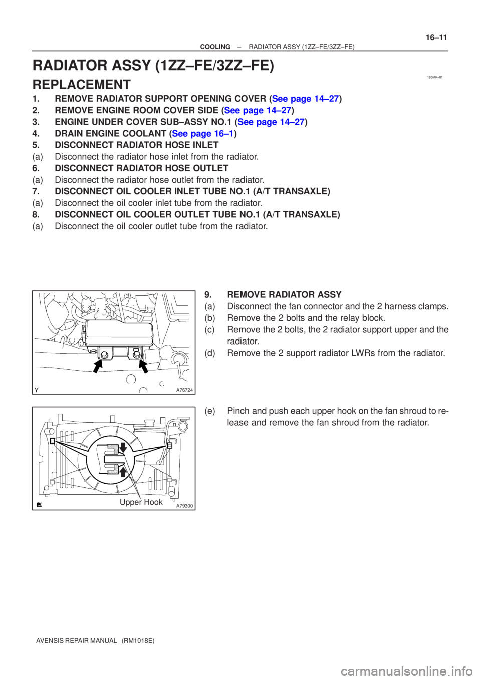
9. REMOVE RADIATOR ASSY
(a) Disconnect the fan connector and the 2 harness clamps.
(b) Remove the 2 bolts and the relay block.
(c) Remove the 2 bolts, the 2 radiator support upper and theradiator.
(d) Remove the 2 support radiator LWRs from the radiator.
(e) Pinch and push each upper hook on the fan shroud to re- lease and remove the fan shroud from the radiator.
Page 2359 of 5135
160N4±01
A79037
± COOLINGCOOLING SYSTEM (1ZZ±FE/3ZZ±FE)
16±1
AVENSIS REPAIR MANUAL (RM1018E)
COOLING SYSTEM (1ZZ±FE/3ZZ±FE)
ON±VEHICLE INSPECTION
1. INSPECT COOLING SYSTEM FOR LEAKS
CAUTION:
To avoid the danger of being burned, do not remove the ra-
diator cap while the engine and radiator are still hot. Ther-
mal expansion will cause hot engine coolant and steam to
blow out from the radiator.
(a) Remove the radiator support opening cover.
(b) Remove the engine room cover side.
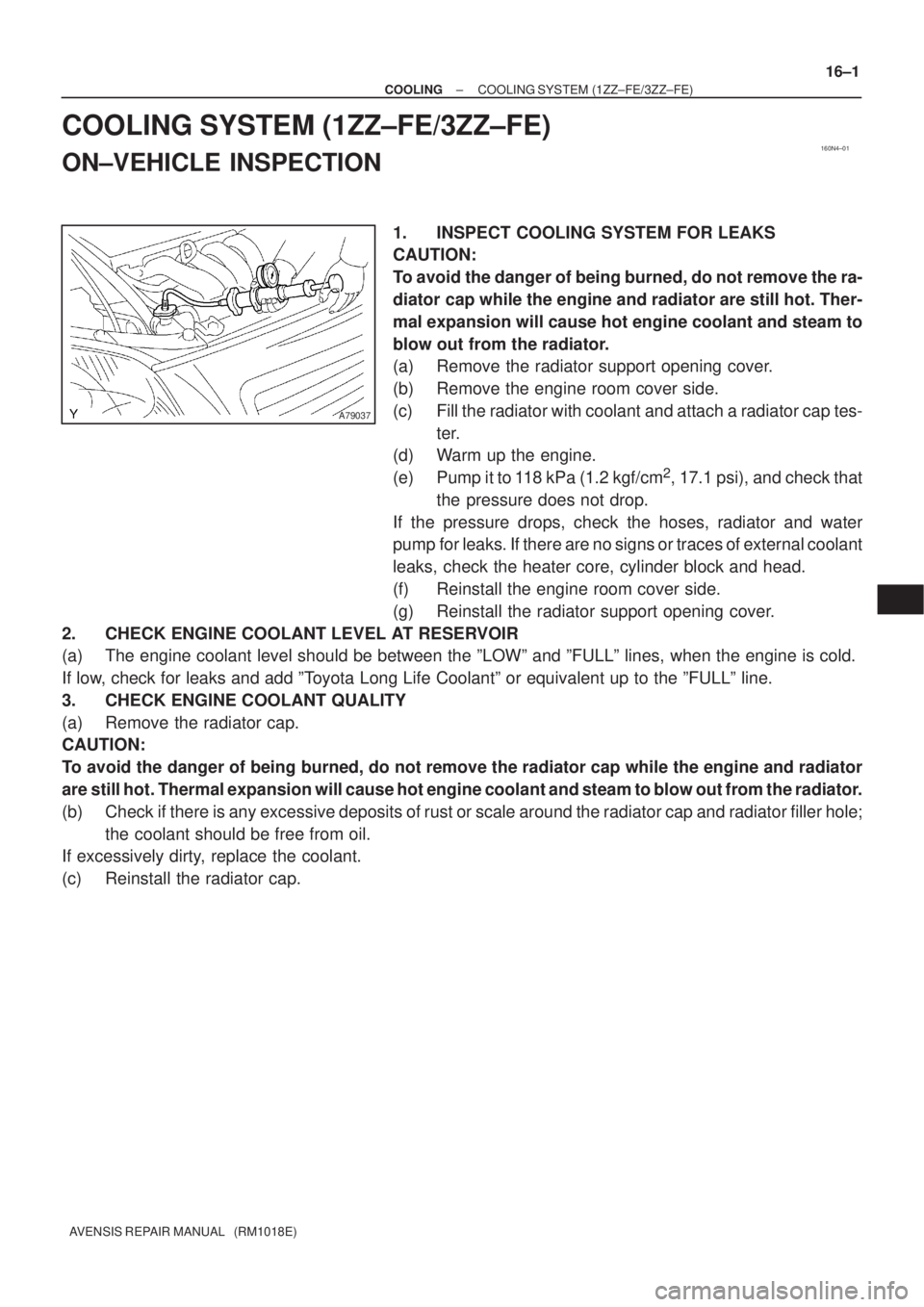
(c) Fill the radiator with coolant and attach a radiator cap tes-
ter.
(d) Warm up the engine.
(e) Pump it to 118 kPa (1.2 kgf/cm
2, 17.1 psi), and check that
the pressure does not drop.
If the pressure drops, check the hoses, radiator and water
pump for leaks. If there are no signs or traces of external coolant
leaks, check the heater core, cylinder block and head.
(f) Reinstall the engine room cover side.
(g) Reinstall the radiator support opening cover.
2. CHECK ENGINE COOLANT LEVEL AT RESERVOIR
(a) The engine coolant level should be between the ºLOWº and ºFULLº lines, when the engine is cold.
If low, check for leaks and add ºToyota Long Life Coolantº or equivalent up to the ºFULLº line.
3. CHECK ENGINE COOLANT QUALITY
(a) Remove the radiator cap.
CAUTION:
To avoid the danger of being burned, do not remove the radiator cap while the engine and radiator
are still hot. Thermal expansion will cause hot engine coolant and steam to blow out from the radiator.
(b) Check if there is any excessive deposits of rust or scale around the radiator cap and radiator filler hole;
the coolant should be free from oil.
If excessively dirty, replace the coolant.
(c) Reinstall the radiator cap.
Page 2379 of 5135
160N6±01
A78434
Radiator Cap Tester
± COOLINGCOOLING SYSTEM (1CD±FTV)
16±37
AVENSIS REPAIR MANUAL (RM1018E)
COOLING SYSTEM (1CD±FTV)
ON±VEHICLE INSPECTION
1. INSPECT COOLING SYSTEM FOR LEAKS
CAUTION:
To avoid the danger of being burned, do not remove the ra-
diator cap while the engine and radiator are still hot. Ther-
mal expansion will cause hot engine coolant and steam to
blow out from the radiator.
(a) Remove the radiator support opening cover.
(b) Remove the engine room cover side.
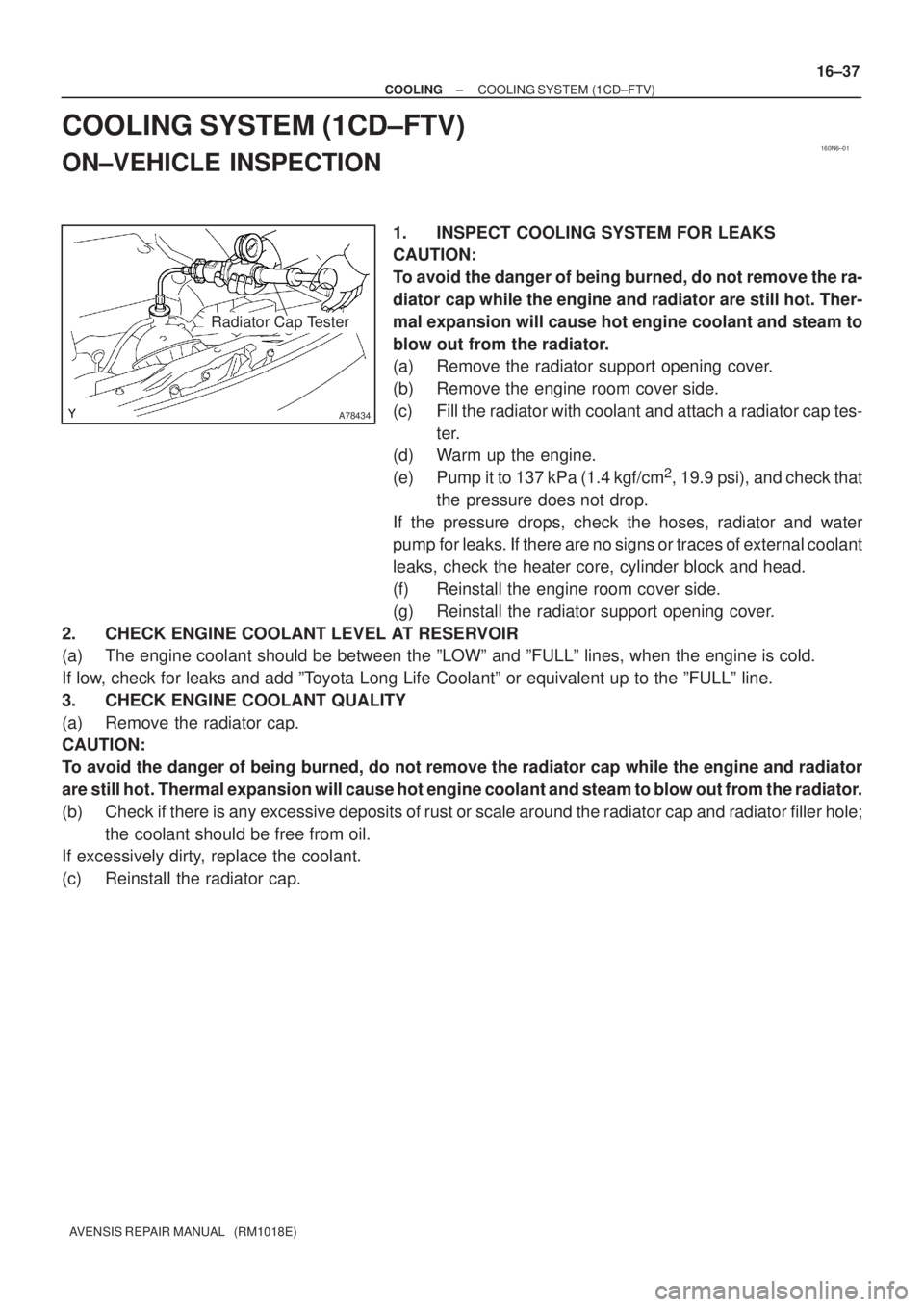
(c) Fill the radiator with coolant and attach a radiator cap tes-
ter.
(d) Warm up the engine.
(e) Pump it to 137 kPa (1.4 kgf/cm
2, 19.9 psi), and check that
the pressure does not drop.
If the pressure drops, check the hoses, radiator and water
pump for leaks. If there are no signs or traces of external coolant
leaks, check the heater core, cylinder block and head.
(f) Reinstall the engine room cover side.
(g) Reinstall the radiator support opening cover.
2. CHECK ENGINE COOLANT LEVEL AT RESERVOIR
(a) The engine coolant should be between the ºLOWº and ºFULLº lines, when the engine is cold.
If low, check for leaks and add ºToyota Long Life Coolantº or equivalent up to the ºFULLº line.
3. CHECK ENGINE COOLANT QUALITY
(a) Remove the radiator cap.
CAUTION:
To avoid the danger of being burned, do not remove the radiator cap while the engine and radiator
are still hot. Thermal expansion will cause hot engine coolant and steam to blow out from the radiator.
(b) Check if there is any excessive deposits of rust or scale around the radiator cap and radiator filler hole;
the coolant should be free from oil.
If excessively dirty, replace the coolant.
(c) Reinstall the radiator cap.
Page 2391 of 5135
160MY±01
A78433
± COOLINGCOOLING SYSTEM (1AZ±FSE)
16±25
AVENSIS REPAIR MANUAL (RM1018E)
COOLING SYSTEM (1AZ±FSE)
ON±VEHICLE INSPECTION
1. INSPECT COOLING SYSTEM FOR LEAKS
CAUTION:
To avoid the danger of being burned, do not remove the ra-
diator cap while the engine and radiator are still hot. Ther-
mal expansion will cause hot engine coolant and steam to
blow out from the radiator.
(a) Remove the radiator support opening cover.
(b) Remove the engine room cover side.
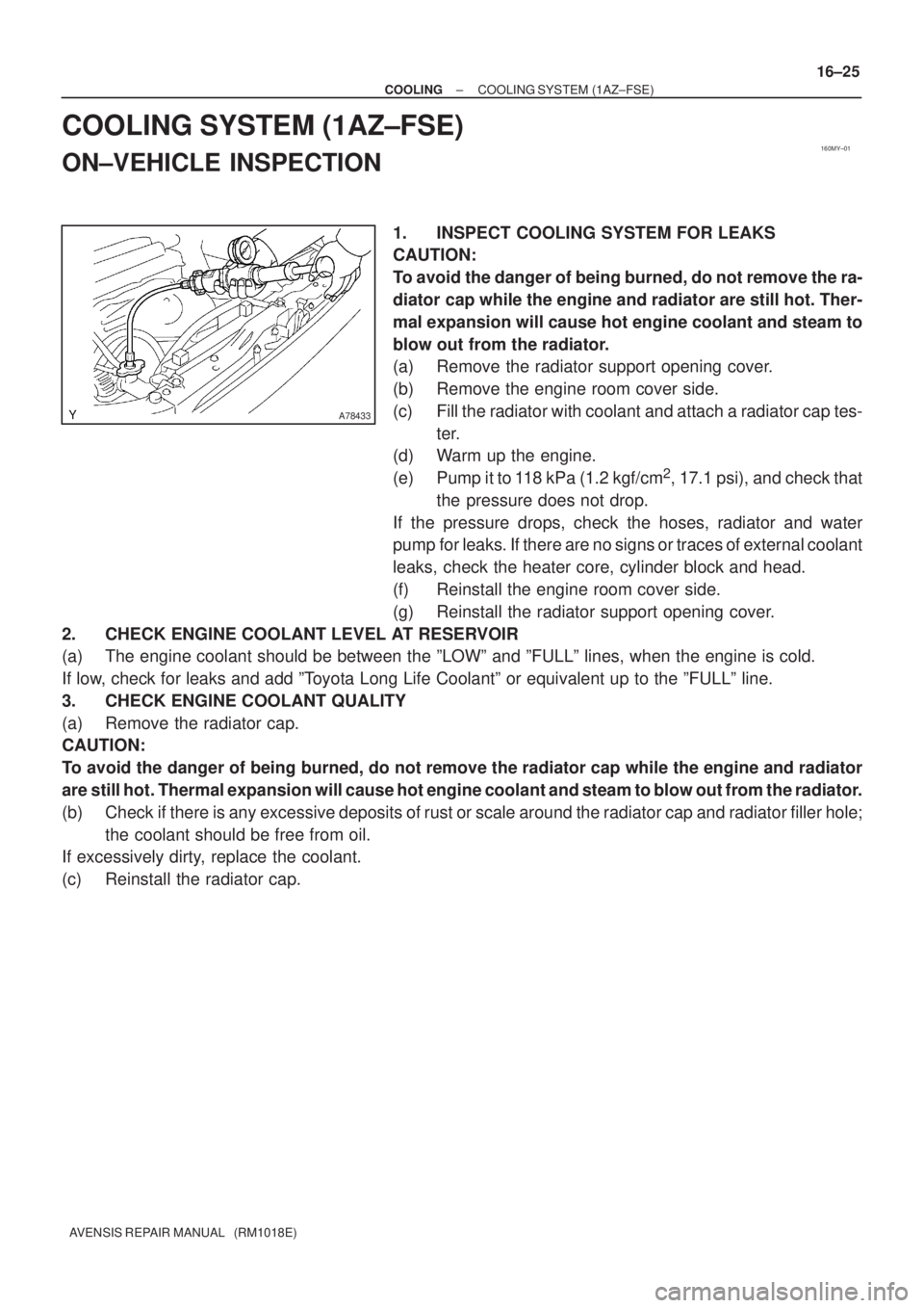
(c) Fill the radiator with coolant and attach a radiator cap tes-
ter.
(d) Warm up the engine.
(e) Pump it to 118 kPa (1.2 kgf/cm
2, 17.1 psi), and check that
the pressure does not drop.
If the pressure drops, check the hoses, radiator and water
pump for leaks. If there are no signs or traces of external coolant
leaks, check the heater core, cylinder block and head.
(f) Reinstall the engine room cover side.
(g) Reinstall the radiator support opening cover.
2. CHECK ENGINE COOLANT LEVEL AT RESERVOIR
(a) The engine coolant should be between the ºLOWº and ºFULLº lines, when the engine is cold.
If low, check for leaks and add ºToyota Long Life Coolantº or equivalent up to the ºFULLº line.
3. CHECK ENGINE COOLANT QUALITY
(a) Remove the radiator cap.
CAUTION:
To avoid the danger of being burned, do not remove the radiator cap while the engine and radiator
are still hot. Thermal expansion will cause hot engine coolant and steam to blow out from the radiator.
(b) Check if there is any excessive deposits of rust or scale around the radiator cap and radiator filler hole;
the coolant should be free from oil.
If excessively dirty, replace the coolant.
(c) Reinstall the radiator cap.
Page 2397 of 5135
170FP±01
SST
A09582
17±22
±
LUBRICATION OIL PUMP ASSY(1CD±FTV)
AVENSIS REPAIR MANUAL (RM1018E)
OIL PUMP ASSY(1CD±FTV)
REPLACEMENT
1.DRAIN ENGINE OIL(See page 17±30)
2.REMOVE RADIATOR SUPPORT OPENING COVER
3.REMOVE ENGINE ROOM COVER SIDE
4.REMOVE FRONT WHEEL RH
5.REMOVE ENGINE UNDER COVER RH
6.REMOVE ENGINE UNDER COVER SUB±ASSY NO.1
7.REMOVE ENGINE COVER NO.1
(a)Remove the 5 nuts and the engine cover.
8.REMOVE INJECTOR DRIVER(See page 14±307)
9.REMOVE V (COOLER COMPRESSOR TO CRANKSHAFT PULLEY) BELT NO.1 (See page 14±269)
10.REMOVE GENERATOR V BELT (See page 14±269)
11.SEPARATE POWER STEERING IDLE PULLEY BRACKET (See page 14±286)
12.REMOVE ENGINE MOUNTING INSULATOR SUB±ASSY RH(See page 14±307)
13.REMOVE CRANKSHAFT PULLEY(See page 14±307) SST09213±54015 (90105±08076), 09330±00021, 09950±50013 (0995\
1±05010, 09952±05010, 09953±05020, 09954±05031)
14.REMOVE IDLER PULLEY SUB±ASSY(See page 14±307)
15.REMOVE TIMING BELT NO.2 COVER(See page 14±307)
16.REMOVE TIMING BELT NO.1 COVER(See page 14±307)
17.REMOVE TIMING BELT GUIDE
18.REMOVE TRANSVERSE ENGINE ENGINE MOUNTING BRACKET(See page 14±307)
19.SET NO. 1 CYLINDER TO TDC/COMPRESSION(See page 14±307)
20.REMOVE TIMING CHAIN COVER PLATE(See page 14±307)
21.REMOVE TIMING BELT(See page 14±307)
22.REMOVE TIMING BELT IDLER SUB±ASSY NO.2(See page 14±307)
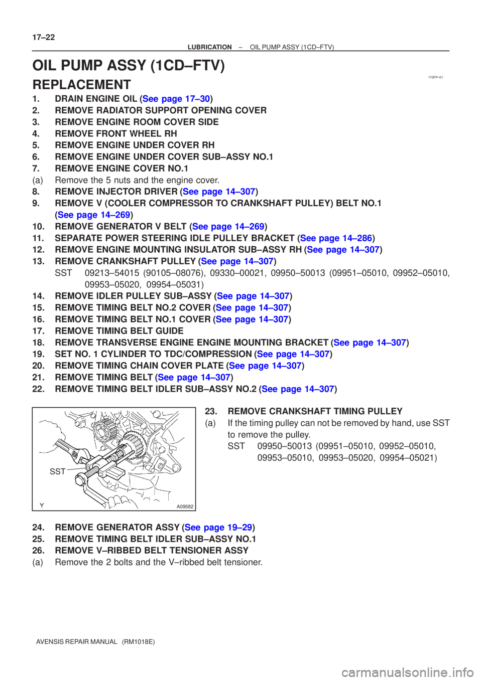
23.REMOVE CRANKSHAFT TIMING PULLEY
(a)If the timing pulley can not be removed by hand, use SSTto remove the pulley.
SST09950±50013 (09951±05010, 09952±05010, 09953±05010, 09953±05020, 09954±05021)
24.REMOVE GENERATOR ASSY(See page 19±29)
25. REMOVE TIMING BELT IDLER SUB±ASSY NO.1
26. REMOVE V±RIBBED BELT TENSIONER ASSY
(a) Remove the 2 bolts and the V±ribbed belt tensioner.
Page 2398 of 5135
A79173
A79174
A56695
A79175
A56696
± LUBRICATIONOIL PUMP ASSY (1CD±FTV)
17±23
AVENSIS REPAIR MANUAL (RM1018E)
27. REMOVE OIL LEVEL GAGE GUIDE
(a) Remove the bolt which is used to secure the oil level gage
guide to the cylinder block.
(b) Pull out the oil level gage guide together with the oil level
gage from the No. 1 oil pan.
(c) Remove the O±ring from the oil level gage guide.
28. REMOVE ENGINE OIL LEVEL SENSOR
(a) Remove the 4 bolts and the level sensor.
NOTICE:
Be careful not to drop the oil level sensor when removing.
29. REMOVE OIL PAN SUB±ASSY NO.2
(a) Remove the 17 bolts and 2 nuts.
(b) Insert the blade of SST between the No. 1 and No. 2 oil
pans, and cut off applied sealer and remove the No. 2 oil
pan.
SST 09032±00100
NOTICE:
Be careful not to damage the No. 1 and No. 2 oil pans.
30. REMOVE OIL STRAINER SUB±ASSY
(a) Remove the 2 bolts and 2 nuts, then remove the oil strain-
er and the gasket.
Page 2399 of 5135
B08009
A56697
A56698
A56699
17±24
± LUBRICATIONOIL PUMP ASSY (1CD±FTV)
AVENSIS REPAIR MANUAL (RM1018E)
31. REMOVE OIL PAN INSULATOR
(a) Remove the bolt and the oil pan insulator.
32. REMOVE OIL PAN SUB±ASSY
(a) Remove the 19 bolts and 3 nuts.
(b) Using a screwdriver, remove the oil pan by prying be-
tween the cylinder block and the No. 1 oil pan.
NOTICE:
Be careful not to damage the cylinder block and No. 1 oil
pan.
33. REMOVE CRANKSHAFT POSITION SENSOR
34. REMOVE OIL PUMP ASSY
(a) Remove the 9 bolts.
(b) Remove the oil pump by prying between the oil pump and
the main bearing cap with a screwdriver.
(c) Remove the gasket.
Page 2400 of 5135
A56700
SST
B07987
New Gasket
Seal
Packing Seal Width
2 to 4 mm
B08024
± LUBRICATIONOIL PUMP ASSY (1CD±FTV)
17±25
AVENSIS REPAIR MANUAL (RM1018E)
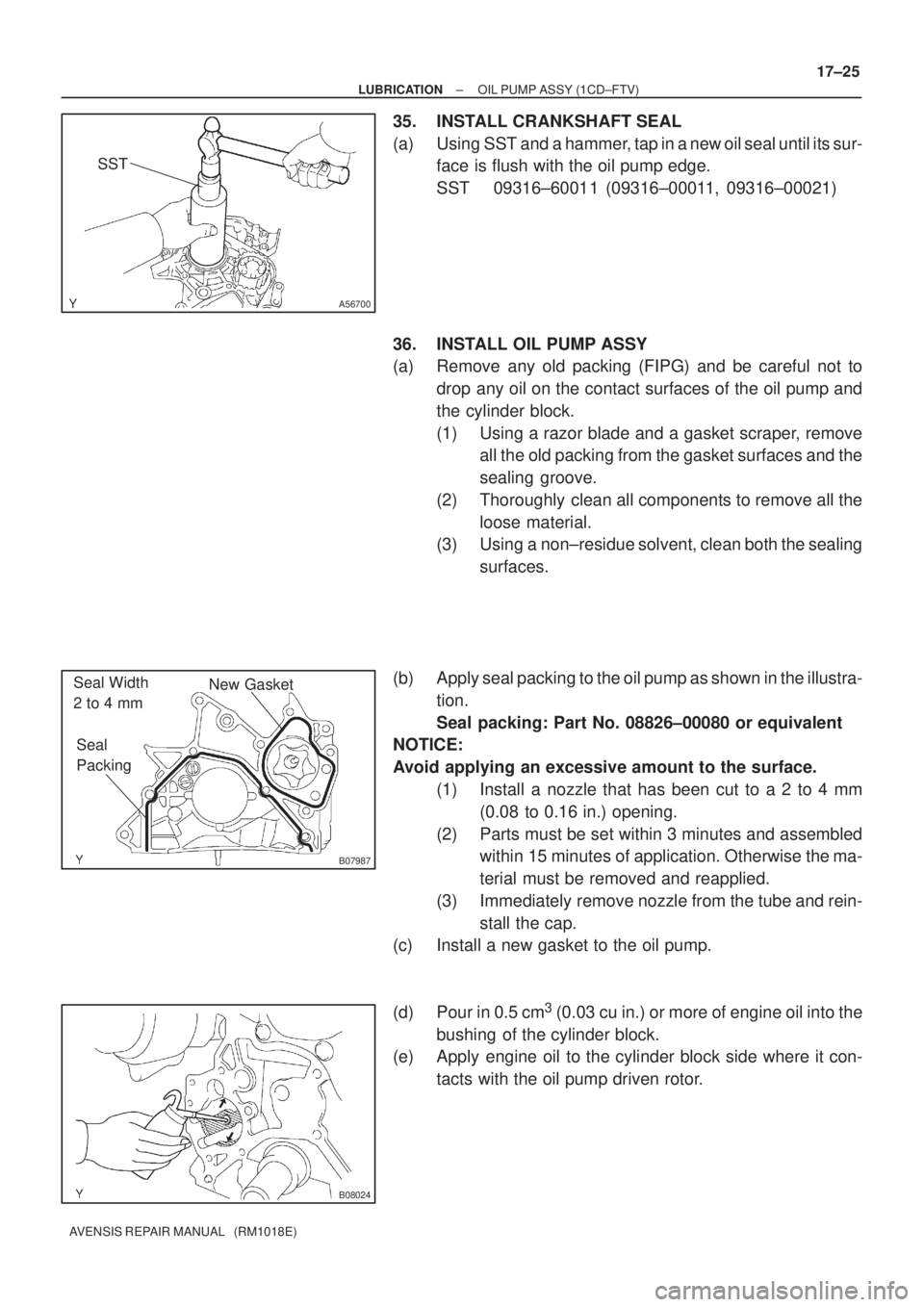
35. INSTALL CRANKSHAFT SEAL
(a) Using SST and a hammer, tap in a new oil seal until its sur-
face is flush with the oil pump edge.
SST 09316±60011 (09316±00011, 09316±00021)
36. INSTALL OIL PUMP ASSY
(a) Remove any old packing (FIPG) and be careful not to
drop any oil on the contact surfaces of the oil pump and
the cylinder block.
(1) Using a razor blade and a gasket scraper, remove
all the old packing from the gasket surfaces and the
sealing groove.
(2) Thoroughly clean all components to remove all the
loose material.
(3) Using a non±residue solvent, clean both the sealing
surfaces.
(b) Apply seal packing to the oil pump as shown in the illustra-
tion.
Seal packing: Part No. 08826±00080 or equivalent
NOTICE:
Avoid applying an excessive amount to the surface.
(1) Install a nozzle that has been cut to a 2 to 4 mm
(0.08 to 0.16 in.) opening.
(2) Parts must be set within 3 minutes and assembled
within 15 minutes of application. Otherwise the ma-
terial must be removed and reapplied.
(3) Immediately remove nozzle from the tube and rein-
stall the cap.
(c) Install a new gasket to the oil pump.
(d) Pour in 0.5 cm
3 (0.03 cu in.) or more of engine oil into the
bushing of the cylinder block.
(e) Apply engine oil to the cylinder block side where it con-
tacts with the oil pump driven rotor.