Page 2305 of 5135

AVENSIS REPAIR MANUAL (RM1018E)
(e)Insta")
A09601
Seal Packing
A09627
A09650
12
3
5
49
6
8
7
13
10
11
15
14 12
A09600
Seal Width
2 to 4 mm
Seal Packing
14±322
±
ENGINE MECHANICAL CAMSHAFT(1CD±FTV)
AVENSIS REPAIR MANUAL (RM1018E)
(e)Install the camshaft bearing caps. (1)Remove any oil packing (FIPG) material from theNo. 5 camshaft bearing cap.
(2)Apply seal packing to the No. 5 camshaft bearing cap as shown in the illustration.
Seal packing: Part No. 08826±00080 or equivalent
(3)Place the 5 bearing caps in their proper locations.
(4)Using several steps, install and tighten the 15 bear- ing cap bolts uniformly in the sequence shown in the
illustration.
Torque: 20 N �m (204 kgf �cm, 15 ft �lbf)
43.INSPECT VALVE CLEARANCE (See page 14±270)
44.ADJUST VALVE CLEARANCE (See page 14±270) 45. INSTALL CAMSHAFT OIL SEAL RETAINER
(a) Remove any old packing (FIPG) material and be carefulnot to drop any oil on the contact surfaces of the oil seal
retainer and the cylinder block.
(1) Thoroughly clean all components to remove all theloose material.
(2) Using non±residue solvent, clean both sealing sur- faces.
(b) Apply seal packing to the oil seal retainer as shown in the illustration.
Seal packing: Part No. 08826±00080 or equivalent
(1) Install a nozzle that has been cut to a 2 to 4 mm(0.08 to 0.16 in.) opening.
(2) Parts must be assembled within 15 minutes of ap- plication. Otherwise the material must be removed
and reapplied.
(3) Immediately remove nozzle from the tube and rein- stall the cap.
Page 2306 of 5135

14±323
AVENSIS REPAIR MANUAL (RM1018E)
(c)Install the oil seal retainer with the 4 bolts. Tighten the 4
bolts uniformly in se")
A62592
SST
A09663
:Seal Packing
±
ENGINE MECHANICAL CAMSHAFT(1CD±FTV)
14±323
AVENSIS REPAIR MANUAL (RM1018E)
(c)Install the oil seal retainer with the 4 bolts. Tighten the 4
bolts uniformly in several steps.
Torque: 8.8 N �m (90 kgf �cm, 78 in. �lbf)
46.INSTALL CAMSHAFT TIMING PULLEY
(a)Install the pulley set key to the groove of the camshaft.
(b)Align the keyway of the timing pulley with the key located on the camshaft, slide the pulley into place.
(c)Using SST, install the pulley bolt. SST09960±10010 (09962±01000, 09963±01000)
Torque: 88 N �m (899 kgf �cm, 65 ft �lbf)
47.INSTALL CAMSHAFT POSITION SENSOR (See page 10±63)
48.INSTALL INJECTOR ASSY (See page 11±60)
49.INSTALL NOZZLE LEAKAGE PIPE ASSY(See page 11±60) SST09992±00242
50.INSTALL CYLINDER HEAD COVER SUB±ASSY
(a)Remove any old packing (FIPG) material.
(b)Apply seal packing to the cylinder head.Seal packing: Part No. 08826±00080 or equivalent
(c)Install the gasket to the cylinder head cover.
(d)Install the cylinder head cover with the 10 bolts.
Torque: 13 N �m (135 kgf �cm, 9.7 ft �lbf)
51.INSTALL NOZZLE HOLDER SEAL
(a)Install 4 new nozzle holder seals.
52.INSTALL VACUUM PUMP ASSY Torque: 21 N �m (214 kgf �cm,15 ft �lbf)
53.INSTALL INJECTION PIPE SUB±ASSY NO.1 (See page 11±60)
NOTICE:
When assembling the pipes, perform the operation with the
engine cold under room temperature.
(a) Remove the vinyl or the plastic bag from the injector and vinyl tape from the common rail.
(b) Temporarily install the injection pipe.
Page 2312 of 5135
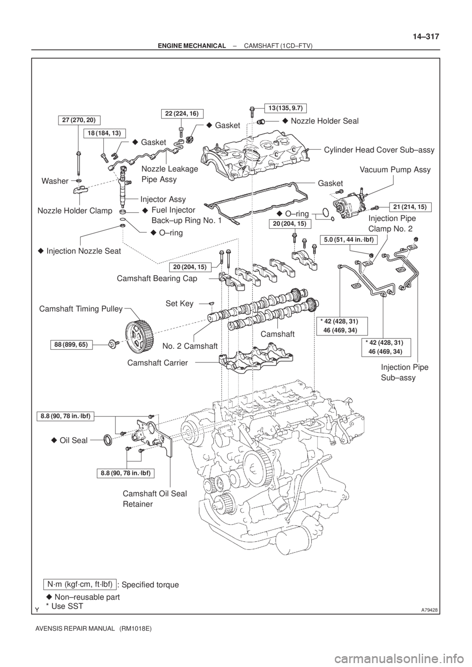
A79428
N´m (kgf´cm, ft´lbf)
: Specified torque
� Non±reusable part� Gasket
18 (184, 13)
27 (270, 20)22 (224, 16)13 (135, 9.7)
� Gasket
� O±ring Fuel Injector
Back±up Ring No. 1 �
� Injection Nozzle Seat
8.8 (90, 78 in.�lbf)
� Oil Seal
8.8 (90, 78 in.�lbf)
20 (204, 15)
Washer
Nozzle Holder ClampNozzle Leakage
Pipe Assy
Injector AssyCylinder Head Cover Sub±assy
Gasket
Camshaft Bearing Cap
No. 2 CamshaftCamshaft
Camshaft Carrier
Camshaft Oil Seal
Retainer
88 (899, 65)
Camshaft Timing PulleySet Key
20 (204, 15)
* 42 (428, 31)
46 (469, 34)
Injection Pipe
Clamp No. 2
Injection Pipe
Sub±assy � O±ring
21 (214, 15)
Vacuum Pump Assy
5.0 (51, 44 in.�lbf)
� Nozzle Holder Seal
* Use SST
* 42 (428, 31)
46 (469, 34)
± ENGINE MECHANICALCAMSHAFT (1CD±FTV)
14±317
AVENSIS REPAIR MANUAL (RM1018E)
Page 2314 of 5135

AVENSIS REPAIR MANUAL (RM1018E)
(b) Using SST, remove the pulley.
SST 09950±50013 (09951±05010, 09952±05010,
09953±")
A61183SST
A09605Turn
A61185
14±308
± ENGINE MECHANICALTIMING BELT (1CD±FTV)
AVENSIS REPAIR MANUAL (RM1018E)
(b) Using SST, remove the pulley.
SST 09950±50013 (09951±05010, 09952±05010,
09953±05020, 09954±05031)
13. REMOVE IDLER PULLEY SUB±ASSY
(a) Remove the bolt and washer, and then remove the pulley.
14. REMOVE TIMING BELT NO.2 COVER
(a) Remove the 7 bolts and 7 seal washers, and then remove the timing belt cover.
15. REMOVE TIMING BELT NO.1 COVER
(a) Remove the 5 bolts and 5 seal washers, and then remove the timing belt cover.
16. REMOVE TIMING BELT GUIDE
17. REMOVE TRANSVERSE ENGINE ENGINE MOUNTING BRACKET
(a) Remove the 6 bolts and the engine mounting bracket.
18. SET NO. 1 CYLINDER TO TDC/COMPRESSION
(a) Using the crankshaft pulley bolt, align the dot mark of the
crankshaft timing pulley with the TDC mark of the oil pump
by turning the crankshaft.
(b) Check that the timing mark of the camshaft timing pulley
is aligned with a joint of the cylinder head and the cylinder
head cover.
If not, revolve the crankshaft 1 revolution (360�) to align the
mark.
19. REMOVE TIMING CHAIN COVER PLATE
(a) Remove the bolt and the timing chain cover plate.
Page 2315 of 5135

14±309
AVENSIS REPAIR MANUAL (RM1018E)
20. REMOVE TIMING BELT
HINT:
If re±use the timing belt, draw an arrow on th")
A09609
A09680
SST
A09611
A09606
A09609
± ENGINE MECHANICALTIMING BELT (1CD±FTV)
14±309
AVENSIS REPAIR MANUAL (RM1018E)
20. REMOVE TIMING BELT
HINT:
If re±use the timing belt, draw an arrow on the belt which indi-
cates the engine revolution direction and put match marks on
the pulleys and the belt before removing. This operation will be
very helpful when re±installing the timing belt.
(a) Alternately loosen the 2 bolts to remove the timing belt
tensioner.
(b) Remove the timing belt.
21. SET NO. 1 CYLINDER TO TDC/COMPRESSION
(a) Using SST, set the pulleys of the camshaft and the injec-
tion pump so that each timing mark of the pulleys is
aligned with its timing mark on the cylinder head assem-
bly and the water pump assembly.
SST 09960±10010 (09962±01000, 09963±01000)
(b) Using the crankshaft pulley bolt, align the dot mark of the
crankshaft timing pulley with the TDC mark of the oil pump
by turning the crankshaft.
NOTICE:
Take great care, when turning the camshaft and crank-
shaft. Since the valve head and the piston head are sensi-
tive, damage to them may result when the piston head con-
tacts with the valve heads.
22. INSTALL TIMING BELT
NOTICE:
The engine should be cold.
(a) Remove any oil or water on each pulley and keep them
clean.
NOTICE:
Do not use any cleaning agent.
Page 2316 of 5135

(A)
A09623
A61179
Hexagon
Wrench
(1.27 mm)
A09605
Turn
Dot Mark
TDC Mark
14±310
± ENGINE MECHANICALTIMING BELT (1CD±FTV)
AVENSI")
A09612
1st
2nd 5th
3rd
4th 6th 7th
A09589
Hexagon
Wrench
(1.27 mm)
(A)
A09623
A61179
Hexagon
Wrench
(1.27 mm)
A09605
Turn
Dot Mark
TDC Mark
14±310
± ENGINE MECHANICALTIMING BELT (1CD±FTV)
AVENSIS REPAIR MANUAL (RM1018E)
(b) Install the timing belt in the following order:
1. Camshaft timing pulley
2. Supply pump drive pulley
3. Water pump pulley
4. Crankshaft timing pulley
5. No. 2 idler pulley
6. Oil pump pulley
7. No. 1 idler pulley
(c) Install the timing belt tensioner.
(1) Using a press, slowly press in the push rod with
pressure 981 to 9,807 N (100 to 1,000 kgf, 200 to
2,205 lbf).
(2) Align the holes of the push rod and the housing, in-
sert hexagon wrench (1.27 mm) through the holes
to keep the setting position of the push rod.
(3) Release the press.
(4) Temporarily install the tensioner with bolt (A).
(5) Turn the tensioner clockwise and temporarily install
the other bolt.
(6) Alternately tighten the 2 bolts.
Torque: 21 N´m (214 kgf´cm, 15 ft´lbf)
(7) Remove the hexagon wrench from the tensioner.
23. CHECK VALVE TIMING
(a) Slowly turn the crankshaft 2 complete revolutions (720�)
from TDC to TDC.
NOTICE:
Always turn the crankshaft clockwise.
Page 2322 of 5135

AVENSIS REPAIR MANUAL (RM1018E)
REPLACEMENT
1.REMOVE FRONT WHEELS
2.REMOVE ENGINE UNDER COVER LH
3.REMOVE ENGINE UNDER COV")
141C4±01
A80094
14±286
±
ENGINE MECHANICAL PARTIAL ENGINE ASSY(1CD±FTV)
AVENSIS REPAIR MANUAL (RM1018E)
REPLACEMENT
1.REMOVE FRONT WHEELS
2.REMOVE ENGINE UNDER COVER LH
3.REMOVE ENGINE UNDER COVER SUB±ASSY NO.1
4.REMOVE ENGINE UNDER COVER RH
5.REMOVE RADIATOR SUPPORT OPENING COVER
6.REMOVE ENGINE ROOM COVER SIDE
7.DRAIN ENGINE COOLANT (See page 16±44)
8.DRAIN ENGINE OIL (See page 14±342)
9.DRAIN MANUAL TRANSAXLE OIL Torque: 49 N �m (500 kgf �cm,36 ft �lbf)
10.REMOVE ENGINE COVER NO.1
(a)Remove the 5 nuts and the engine cover.
11.REMOVE BATTERY
12.REMOVE AIR CLEANER ASSY
(a)Disconnect the connector.
(b)Remove the air cleaner cap together with the air cleaner hose.
(c)Remove the air cleaner filter element.
(d)Remove the 3 bolts and the air cleaner case.
13.DISCONNECT UNION TO CONNECTOR TUBE HOSE
14.REMOVE FUEL FILTER ASSY
(a)Disconnect the 2 fuel hose from the fuel filter (STD).
(b)Disconnect the 3 fuel hose from the fuel filter (COLD).
(c)Disconnect the connector (STD).
(d)Disconnect the 2 connectors (COLD).
(e)Remove the 2 bolts and the fuel filter.
15.REMOVE RADIATOR HOSE INLET
16.REMOVE RADIATOR HOSE OUTLET
17.DISCONNECT WATER BY±PASS HOSE NO.2
18.REMOVE ENGINE ROOM RELAY BLOCK NO.3
(a)Remove the 2 bolts and the engine room relay block.
19.REMOVE RADIATOR ASSY (W/ AIR CONDITIONING) (See page 16±51)
20. DISCONNECT HEATER INLET WATER HOSE
21. DISCONNECT HEATER OUTLET WATER HOSE
22. DISCONNECT FUEL HOSE NO.2
23. REMOVE AIR TUBE NO.2
(a) Loosen the hose clamp and disconnect the air hose No.3.
(b) Remove the 2 bolts and the air tube No. 2.
Page 2324 of 5135

AVENSIS REPAIR MANUAL (RM1018E)
34.SEPARATE RETURN TUBE SUB±ASSY
(a)Remove the 2 clamp bolts and separate the return tube su")
A79140
A79184
14±288
±
ENGINE MECHANICAL PARTIAL ENGINE ASSY(1CD±FTV)
AVENSIS REPAIR MANUAL (RM1018E)
34.SEPARATE RETURN TUBE SUB±ASSY
(a)Remove the 2 clamp bolts and separate the return tube sub±assy.
35.SEPARATE VANE PUMP OIL RESERVOIR ASSY
36.REMOVE FRONT AXLE HUB LH NUT (See page 30±6) SST09930±00010
HINT:
Perform the same procedure as above on the opposite side.
37.SEPARATE TIE ROD END SUB±ASSY LH (See page 30±6) SST 09628±62011
HINT:
Perform the same procedure as above on the opposite side.
38.SEPARATE FRONT STABILIZER LINK ASSY LH (See page 26±26)
HINT:
Perform the same procedure as above on the opposite side.
39. REMOVE COLUMN HOLE COVER SILENCER SHEET
(a) Remove the 2 clips and the column hole cover silencer sheet.
40.REMOVE STEERING INTERMEDIATE SHAFT ASSY NO.2 (See page 51±36)
41.SEPARATE FRONT SUSPENSION ARM SUB±ASSY LOWER NO.1 LH (See page 26±21)
HINT:
Perform the same procedure as above on the opposite side.
42.SEPARATE FRONT DRIVE SHAFT ASSY LH (See page 30±6)
HINT:
Perform the same procedure as above on the opposite side.
43. REMOVE ENGINE ASSEMBLY WITH TRANSAXLE
(a) Disconnect the height control sensor connector (w/ Dis-charge head lamp).