Page 2966 of 5135

201 mm (7.91 in.)
67 mm
(2.63 in.)
50 mm
(1.96 in.)
I35313
������I37394
I35311
I35300
55±62
± HEATER & AIR CONDITIONERAIR CONDITIONING RADIATOR ASSY
AVENSIS REPAIR MANUAL")
I36812
107 mm
(4.21 in.)
201 mm (7.91 in.)
67 mm
(2.63 in.)
50 mm
(1.96 in.)
I35313
������I37394
I35311
I35300
55±62
± HEATER & AIR CONDITIONERAIR CONDITIONING RADIATOR ASSY
AVENSIS REPAIR MANUAL (RM1018E)
32. INSTALL COOLER THERMISTOR NO.1
(a) Install the cooler thermistor No.1 as shown in the illustra-
tion.
(b) Install the cooler evaporator sub±assy No.1 on the case.
(c) Install the cover with the 6 screws.
33. INSTALL COOLER EXPANSION VALVE (W/O HOT
GAS HEATER)
(a) Install the cooler expansion valve.
34. INSTALL AIR CONDITIONING TUBE ASSY
(a) w/o Hot gas heater:
Sufficiently apply compressor oil to 2 new O±rings and the
fitting surface of the air conditioning tube assy.
Compressor oil: ND±OIL 8 equivalent
(b) w/o Hot gas heater:
Install the 2 O±rings on the air conditioning tube assy.
(c) Using a hexagon wrench 4.0 mm (0.15 in.), install the air
conditioning tube assy with the 2 hexagon bolts.
Torque: 3.5 N�m (35 kgf�cm, 30 in.�lbf)
35. INSTALL AIR CONDITIONER UNIT ASSY
(a) Install the air conditioner unit assy with the 2 bolts and 2
nuts.
Torque: 9.8 N�m (100 kgf�cm, 87 in.�lbf)
Page 2967 of 5135

(b) Install the 2 nuts.
(c) Connect the connectors and the clip.
36. I")
I35299
I06878
ConnectGapWrong
±
HEATER & AIR CONDITIONER AIR CONDITIONING RADIATOR ASSY
55±63
AVENSIS REPAIR MANUAL (RM1018E)
(b) Install the 2 nuts.
(c) Connect the connectors and the clip.
36. INSTALL COOLER REFRIGERANT SUCTION HOSE
NO.1
(a) Remove the attached vinyl tape from the hose.
(b) Sufficiently apply compressor oil to a new O±ring and the fitting surface of the cooler refrigerant suction hose No.1.
Compressor oil: ND±OIL 8 or equivalent
(c) Install the 2 O±rings on the cooler refrigerant suction hose No.1.
(d) Install the cooler refrigerant suction hose No.1 and piping clamp.
HINT:
After the connection, check the claw fitting of the piping clamp.
37. INSTALL LIQUID TUBE SUB±ASSY A
(a) Remove the attached vinyl tape from the tube.
(b) Sufficiently apply compressor oil to a new O±ring and the fitting sur\
face of the liquid tube sub±assy A.
Compressor oil: ND±OIL 8 or equivalent
(c) Install the 2 O±rings on the liquid tube sub±assy A.
(d) Install the liquid tube sub±assy A and the piping clamp.
HINT:
After the connection, check the claw fittings of the piping clamp.
38. ADD ENGINE COOLANT 3ZZ±FE/1ZZ±FE: (See page 16±7)
1AZ±FSE: (See page 16±31)
1AZ±FE: (See page 16±19)
1CD±FTV: (See page 16±44)
39. CHECK FOR ENGINE COOLANT LEAKS 3ZZ±FE/1ZZ±FE: (See page 16±1)
1AZ±FSE: (See page 16±25)
1AZ±FE: (See page 16±13)
1CD±FTV: (See page 16±37)
40.CHARGE REFRIGERANT (See page 55±38) SST 07110±58060 (07117±58060, 07117±58070, 07117±58080, 07117±58090, 07117±78050, 07117±88060, 07117±88070, 07117±88080)
Specified amount: 440 � 30 g (15.51 � 1.06 oz.)
41.WARM UP ENGINE (See page 55±38)
42.INSPECT LEAKAGE OF REFRIGERANT (See page 55±38)
Page 3002 of 5135
I32994
I32994
������I32475
I32993
14 mm
(0.55 in.)
Hexagon
Wrench
Modulator
55±96
± HEATER & AIR CONDITIONERW/RECEIVER CONDENSER ASSY
AVENSIS REPAIR MANUAL (RM1018E)
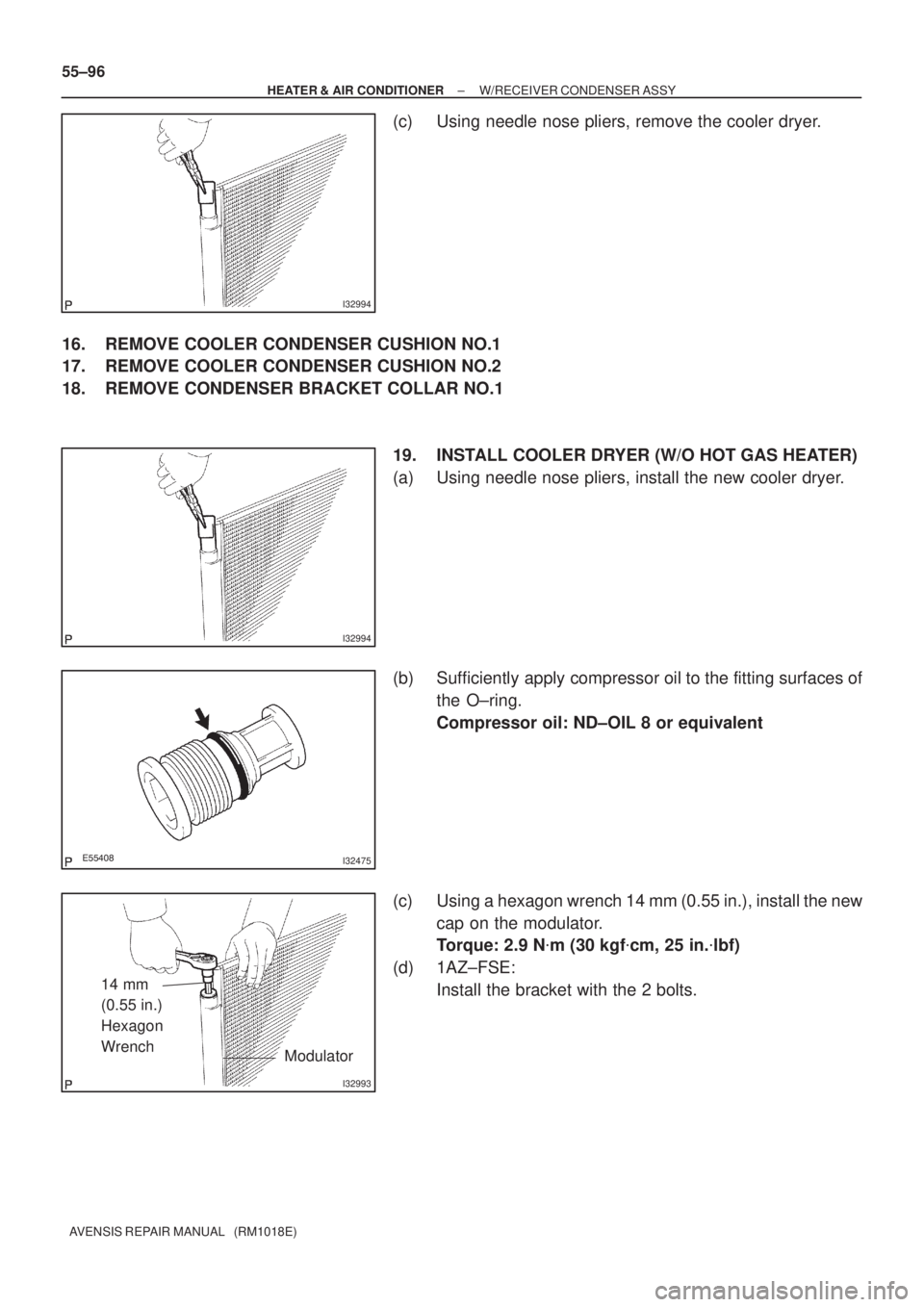
(c) Using needle nose pliers, remove the cooler dryer.
16. REMOVE COOLER CONDENSER CUSHION NO.1
17. REMOVE COOLER CONDENSER CUSHION NO.2
18. REMOVE CONDENSER BRACKET COLLAR NO.1
19. INSTALL COOLER DRYER (W/O HOT GAS HEATER)
(a) Using needle nose pliers, install the new cooler dryer.
(b) Sufficiently apply compressor oil to the fitting surfaces of
the O±ring.
Compressor oil: ND±OIL 8 or equivalent
(c) Using a hexagon wrench 14 mm (0.55 in.), install the new
cap on the modulator.
Torque: 2.9 N�m (30 kgf�cm, 25 in.�lbf)
(d) 1AZ±FSE:
Install the bracket with the 2 bolts.
Page 3003 of 5135

20. I N S TA L L M A G N E T VA LV E A S S Y ( W / H O T G A S
HEATER)
(a) Ins")
I35344
I35343
I35342
I35336
± HEATER & AIR CONDITIONERW/RECEIVER CONDENSER ASSY
55±97
AVENSIS REPAIR MANUAL (RM1018E)
20. I N S TA L L M A G N E T VA LV E A S S Y ( W / H O T G A S
HEATER)
(a) Install the magnet valve assy with the 4 bolts.
Torque: 3.4 N�m (35 kgf�cm, 30 in.�lbf)
21. INSTALL REFRIGERANT FILTER (W/ HOT GAS
HEATER)
(a) Install the refrigerant filter to the discharge tube.
22. INSTALL DISCHARGE TUBE (W/ HOT GAS HEATER)
(a) Install the discharge tube with the 2 bolts.
Torque: 5.4 N�m (55 kgf�cm, 47 in.�lbf)
23. INSTALL LIQUID TUBE SUB±ASSY B (RHD(1CD±FTV)
STEERING POSITION TYPE)
(a) Remove the attached vinyl tape from the tube and the
connecting part of the w/ receiver condenser assy.
(b) Sufficiently apply compressor oil to a new O±ring and the
fitting surface of the pipe joint.
Compressor oil: ND±OIL 8 or equivalent
(c) Install the O±ring on the liquid tube sub±assy B.
(d) Install the liquid tube sub±assy B on the w/ receiver con-
denser assy with the bolt.
Torque: 5.4 N�m (55 kgf�cm, 47 in.�lbf)
24. INSTALL DISCHARGE TUBE SUB±ASSY (W/ HOT
GAS HEATER)
(a) Remove the attached vinyl tape from the tube and the
connecting part of the w/ receiver condenser assy.
(b) Sufficiently apply compressor oil to a new 2 O±rings and
the fitting surface of the pipe joint.
Compressor oil: ND±OIL 8 or equivalent
(c) Install the O±ring on the discharge tube sub±assy.
Page 3004 of 5135

(d) Install the discharge tube sub±assy on the w/ receiver
condenser assy with the")
I35337
I35335
I35336
55±98
± HEATER & AIR CONDITIONERW/RECEIVER CONDENSER ASSY
AVENSIS REPAIR MANUAL (RM1018E)
(d) Install the discharge tube sub±assy on the w/ receiver
condenser assy with the bolt.
Torque: 5.4 N�m (55 kgf�cm, 47 in.�lbf)
25. INSTALL LIQUID TUBE SUB±ASSY A
(a) Remove the attached vinyl tape from the tube and the
connecting part of the w/ receiver condenser assy.
(b) Sufficiently apply compressor oil to a new O±ring and the
fitting surface of the pipe joint.
Compressor oil: ND±OIL 8 or equivalent
(c) Install the O±ring on the liquid tube sub±assy A.
(d) w/o Hot gas heater:
Install the liquid tube sub±assy A on the w/ receiver con-
denser assy core with the bolt.
Torque: 5.4 N�m (55 kgf�cm, 47 in.�lbf)
(e) w/ LHD Hot gas heater:
Install the liquid tube sub±assy A on the w/ receiver con-
denser assy with the bolt.
Torque: 5.4 N�m (55 kgf�cm, 47 in.�lbf)
26. INSTALL COOLER REFRIGERANT DISCHARGE
HOSE NO.1
(a) Remove the attached vinyl tape from the tube and the
connecting part of the w/ receiver condenser assy.
(b) Sufficiently apply compressor oil to the O±ring and the fit-
ting surface of the hose joint.
Compressor oil: ND±OIL 8 or equivalent
(c) Install the O±ring on the cooler refrigerant discharge hose
No.1.
Page 3006 of 5135
550ZA±01
I35278
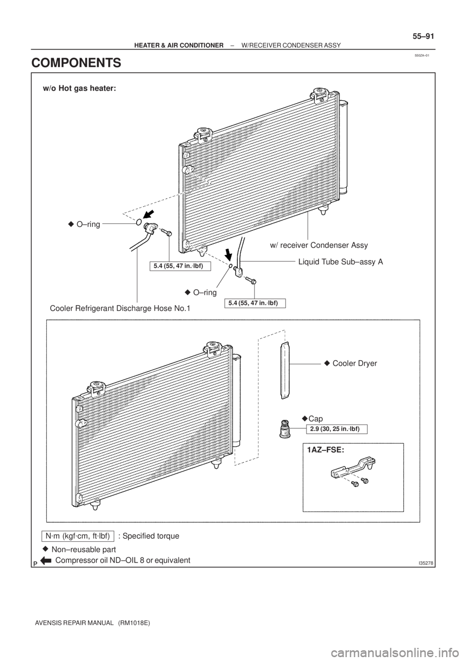
N�m (kgf�cm, ft�lbf) : Specified torque
Non±reusable part �
Compressor oil ND±OIL 8 or equivalentw/ receiver Condenser Assy
Liquid Tube Sub±assy A
Cooler Refrigerant Discharge Hose No.1
Cooler Dryer
Cap
1AZ±FSE: O±ring �
O±ring �
5.4 (55, 47 in.�lbf)
5.4 (55, 47 in.�lbf)
2.9 (30, 25 in.�lbf)
w/o Hot gas heater:
�
�
± HEATER & AIR CONDITIONERW/RECEIVER CONDENSER ASSY
55±91
AVENSIS REPAIR MANUAL (RM1018E)
COMPONENTS
Page 3007 of 5135
I35279
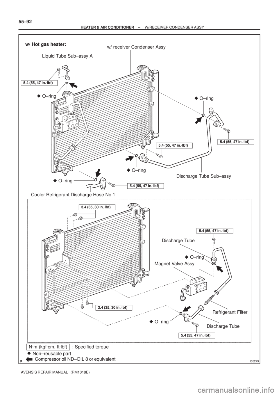
N�m (kgf�cm, ft�lbf) : Specified torque
Non±reusable part �
Compressor oil ND±OIL 8 or equivalentw/ receiver Condenser Assy
Liquid Tube Sub±assy A
Cooler Refrigerant Discharge Hose No.1O±ring �O±ring �
w/ Hot gas heater:
5.4 (55, 47 in.�lbf)
O±ring �
O±ring
�
5.4 (55, 47 in.�lbf)
O±ring �
5.4 (55, 47 in.�lbf)
5.4 (55, 47 in.�lbf)5.4 (55, 47 in.�lbf)
O±ring �
Discharge Tube Sub±assy
5.4 (55, 47 in.�lbf)
3.4 (35, 30 in.�lbf)
3.4 (35, 30 in.�lbf)
Discharge Tube
Discharge Tube
Refrigerant Filter
Magnet Valve Assy
55±92
± HEATER & AIR CONDITIONERW/RECEIVER CONDENSER ASSY
AVENSIS REPAIR MANUAL (RM1018E)
Page 3100 of 5135
650T1±01
I352352Clamps
I35236
I35238
I35239
65±26
±
LIGHTING CENTER STOP LAMP ASSY
AVENSIS REPAIR MANUAL (RM1018E)
CENTER STOP LAMP ASSY
REPLACEMENT
1.REMOVE REAR SPOILER (WAGON MODELS) (See page 76±30)
2.REMOVE BACK DOOR TRIM BOARD ASSY (LIFTBACK MODELS) (See page 75±40) 3. REMOVE CENTER STOP LAMP ASSY (SEDANMODELS)
(a) Remove the center stop lamp assy as shown in the il- lustration.
(b) Disconnect the connector.
(c) Remove the center stop lamp bulb as shown in the il- lustration.
4. REMOVE CENTER STOP LAMP ASSY (WAGON MODELS)
(a) Remove the 2 screws and center stop lamp assy.
5. REMOVE CENTER STOP LAMP ASSY (LIFTBACK MODELS)
(a) Disconnect the connector.
(b) Remove the 3 screws and center stop lamp assy.
(c) Remove the center stop lamp socket and the bulb.

CENTER STOP LAMP ASSY
REPLACEMENT
1.REMOVE REAR SPOILER (WAGON MODELS) (See page")