Page 3477 of 5135
141BU±01
A13845
A77271
Plastigage
A77272
Front Mark
± ENGINE MECHANICALCYLINDER BLOCK ASSY
14±53
1AZ±FSE ENGINE REPAIR MANUAL (RM1019E)
OVERHAUL
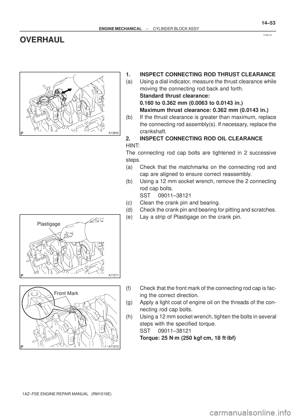
1. INSPECT CONNECTING ROD THRUST CLEARANCE
(a) Using a dial indicator, measure the thrust clearance while
moving the connecting rod back and forth.
Standard thrust clearance:
0.160 to 0.362 mm (0.0063 to 0.0143 in.)
Maximum thrust clearance: 0.362 mm (0.0143 in.)
(b) If the thrust clearance is greater than maximum, replace
the connecting rod assembly(s). If necessary, replace the
crankshaft.
2. INSPECT CONNECTING ROD OIL CLEARANCE
HINT:
The connecting rod cap bolts are tightened in 2 successive
steps.
(a) Check that the matchmarks on the connecting rod and
cap are aligned to ensure correct reassembly.
(b) Using a 12 mm socket wrench, remove the 2 connecting
rod cap bolts.
SST 09011±38121
(c) Clean the crank pin and bearing.
(d) Check the crank pin and bearing for pitting and scratches.
(e) Lay a strip of Plastigage on the crank pin.
(f) Check that the front mark of the connecting rod cap is fac-
ing the correct direction.
(g) Apply a light coat of engine oil on the threads of the con-
necting rod cap bolts.
(h) Using a 12 mm socket wrench, tighten the bolts in several
steps with the specified torque.
SST 09011±38121
Torque: 25 N�m (250 kgf�cm, 18 ft�lbf)
Page 3478 of 5135
A77470
90�
Engine FrontPaint
Mark
A38162
A77471
Mark
1, 2 or 3
Mark
1, 2 or 3
A13469
14±54
± ENGINE MECHANICALCYLINDER BLOCK ASSY
1AZ±FSE ENGINE REPAIR MANUAL (RM1019E)
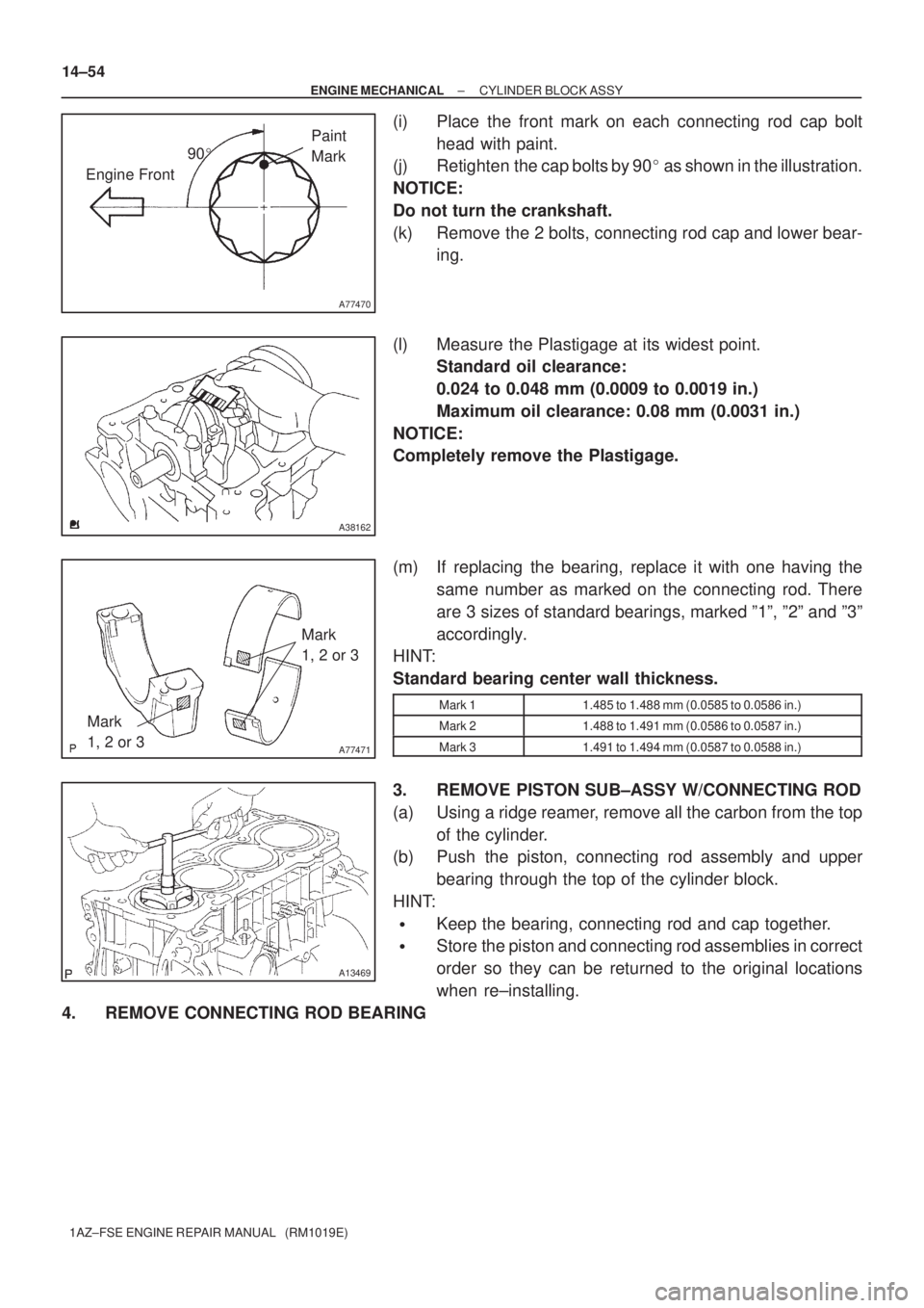
(i) Place the front mark on each connecting rod cap bolt
head with paint.
(j) Retighten the cap bolts by 90� as shown in the illustration.
NOTICE:
Do not turn the crankshaft.
(k) Remove the 2 bolts, connecting rod cap and lower bear-
ing.
(l) Measure the Plastigage at its widest point.
Standard oil clearance:
0.024 to 0.048 mm (0.0009 to 0.0019 in.)
Maximum oil clearance: 0.08 mm (0.0031 in.)
NOTICE:
Completely remove the Plastigage.
(m) If replacing the bearing, replace it with one having the
same number as marked on the connecting rod. There
are 3 sizes of standard bearings, marked º1º, º2º and º3º
accordingly.
HINT:
Standard bearing center wall thickness.
Mark 11.485 to 1.488 mm (0.0585 to 0.0586 in.)
Mark 21.488 to 1.491 mm (0.0586 to 0.0587 in.)
Mark 31.491 to 1.494 mm (0.0587 to 0.0588 in.)
3. REMOVE PISTON SUB±ASSY W/CONNECTING ROD
(a) Using a ridge reamer, remove all the carbon from the top
of the cylinder.
(b) Push the piston, connecting rod assembly and upper
bearing through the top of the cylinder block.
HINT:
�Keep the bearing, connecting rod and cap together.
�Store the piston and connecting rod assemblies in correct
order so they can be returned to the original locations
when re±installing.
4. REMOVE CONNECTING ROD BEARING
Page 3479 of 5135
A14289
A13861
A01178
A01179
A13851
± ENGINE MECHANICALCYLINDER BLOCK ASSY
14±55
1AZ±FSE ENGINE REPAIR MANUAL (RM1019E)
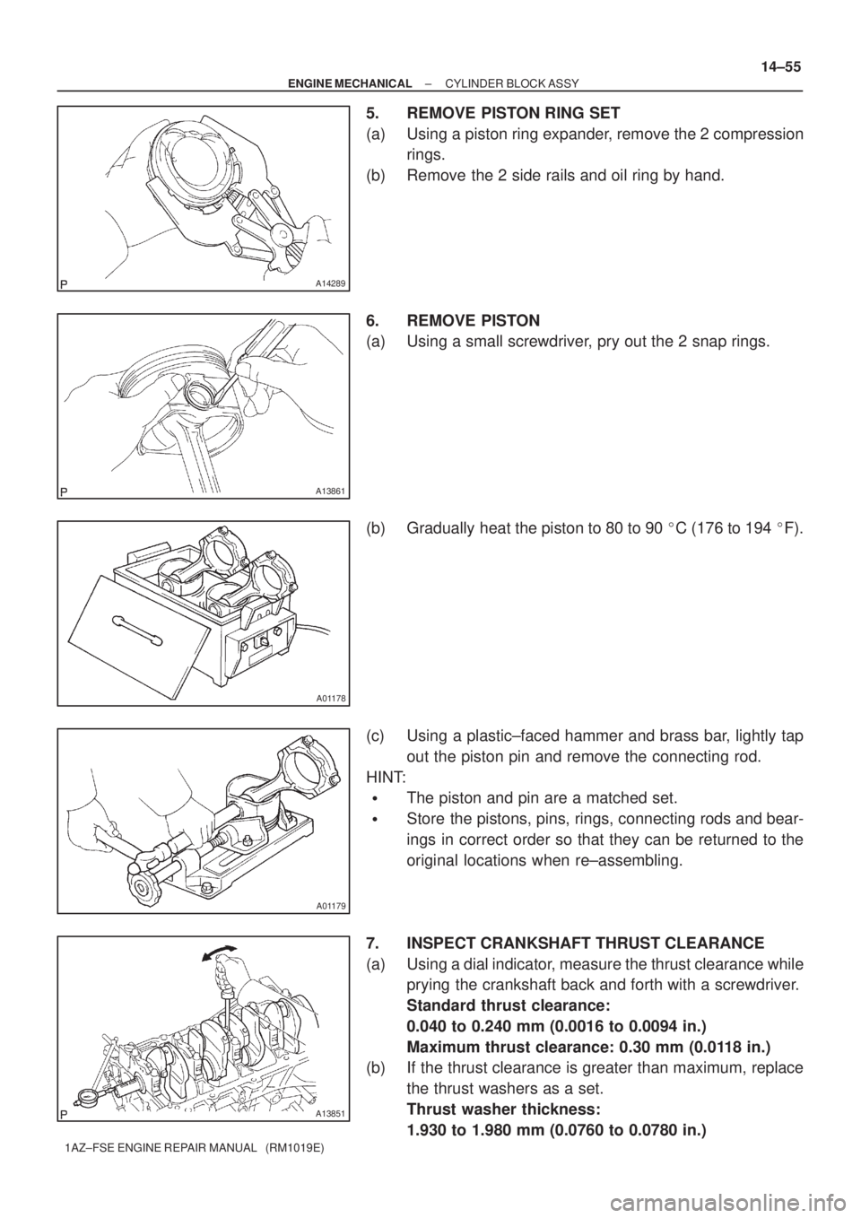
5. REMOVE PISTON RING SET
(a) Using a piston ring expander, remove the 2 compression
rings.
(b) Remove the 2 side rails and oil ring by hand.
6. REMOVE PISTON
(a) Using a small screwdriver, pry out the 2 snap rings.
(b) Gradually heat the piston to 80 to 90 �C (176 to 194 �F).
(c) Using a plastic±faced hammer and brass bar, lightly tap
out the piston pin and remove the connecting rod.
HINT:
�The piston and pin are a matched set.
�Store the pistons, pins, rings, connecting rods and bear-
ings in correct order so that they can be returned to the
original locations when re±assembling.
7. INSPECT CRANKSHAFT THRUST CLEARANCE
(a) Using a dial indicator, measure the thrust clearance while
prying the crankshaft back and forth with a screwdriver.
Standard thrust clearance:
0.040 to 0.240 mm (0.0016 to 0.0094 in.)
Maximum thrust clearance: 0.30 mm (0.0118 in.)
(b) If the thrust clearance is greater than maximum, replace
the thrust washers as a set.
Thrust washer thickness:
1.930 to 1.980 mm (0.0760 to 0.0780 in.)
Page 3481 of 5135
A77472
Thrust Direction
Axial Direction
Front
A
B
10 mm
(0.39 in.)
A78295
30.4 mm
(1.1968 in.)
A36650
± ENGINE MECHANICALCYLINDER BLOCK ASSY
14±57
1AZ±FSE ENGINE REPAIR MANUAL (RM1019E)
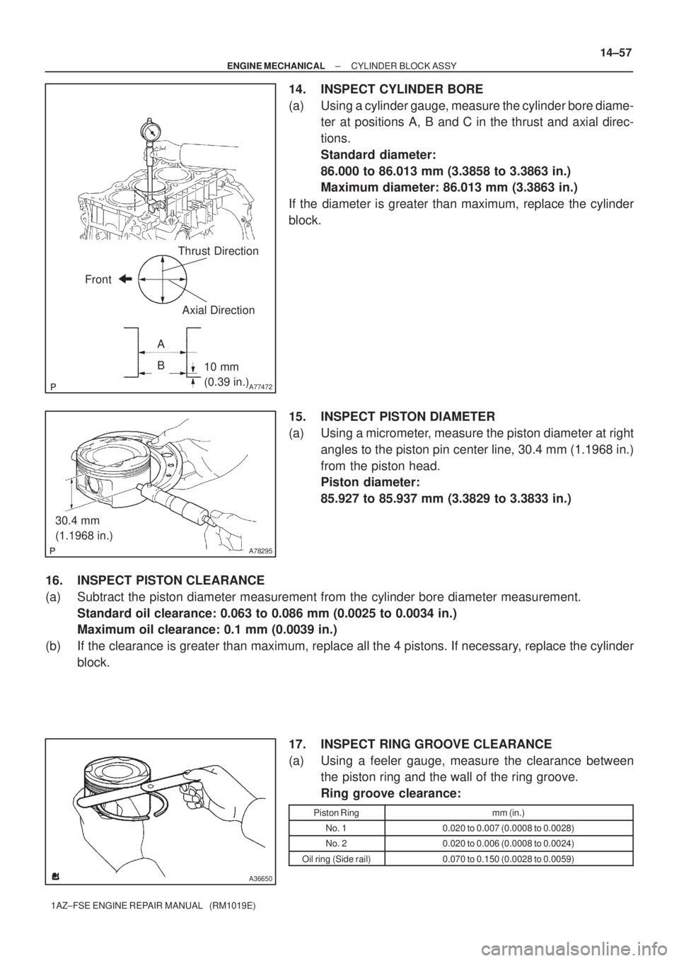
14. INSPECT CYLINDER BORE
(a) Using a cylinder gauge, measure the cylinder bore diame-
ter at positions A, B and C in the thrust and axial direc-
tions.
Standard diameter:
86.000 to 86.013 mm (3.3858 to 3.3863 in.)
Maximum diameter: 86.013 mm (3.3863 in.)
If the diameter is greater than maximum, replace the cylinder
block.
15. INSPECT PISTON DIAMETER
(a) Using a micrometer, measure the piston diameter at right
angles to the piston pin center line, 30.4 mm (1.1968 in.)
from the piston head.
Piston diameter:
85.927 to 85.937 mm (3.3829 to 3.3833 in.)
16. INSPECT PISTON CLEARANCE
(a) Subtract the piston diameter measurement from the cylinder bore diameter measurement.
Standard oil clearance: 0.063 to 0.086 mm (0.0025 to 0.0034 in.)
Maximum oil clearance: 0.1 mm (0.0039 in.)
(b) If the clearance is greater than maximum, replace all the 4 pistons. If necessary, replace the cylinder
block.
17. INSPECT RING GROOVE CLEARANCE
(a) Using a feeler gauge, measure the clearance between
the piston ring and the wall of the ring groove.
Ring groove clearance:
Piston Ringmm (in.)
No. 10.020 to 0.007 (0.0008 to 0.0028)
No. 20.020 to 0.006 (0.0008 to 0.0024)
Oil ring (Side rail)0.070 to 0.150 (0.0028 to 0.0059)
Page 3482 of 5135
A77473Piston Ring4.5 mm
(1.77 in.)
EM2552
A13490
EM0227
A01185
14±58
± ENGINE MECHANICALCYLINDER BLOCK ASSY
1AZ±FSE ENGINE REPAIR MANUAL (RM1019E)
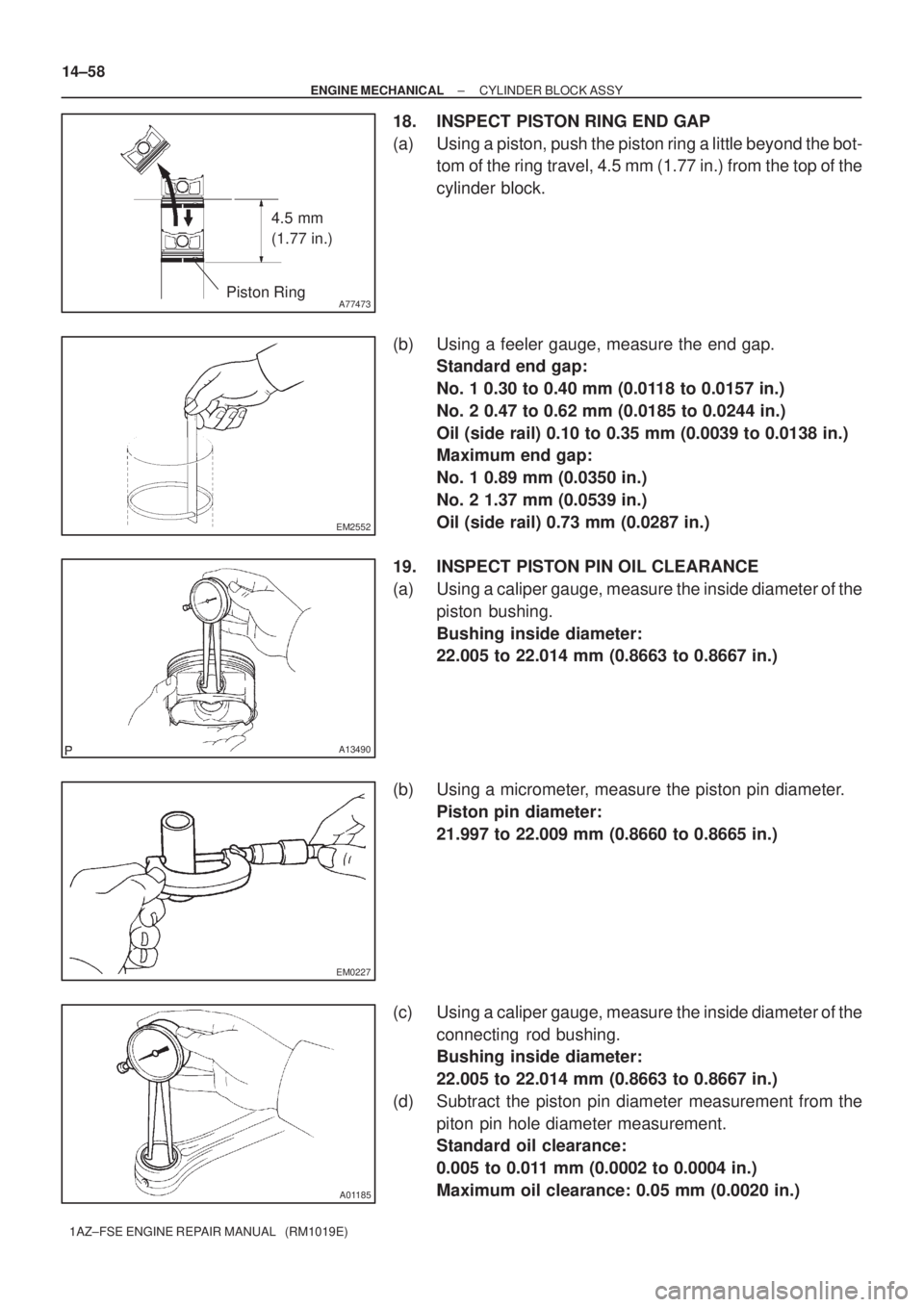
18. INSPECT PISTON RING END GAP
(a) Using a piston, push the piston ring a little beyond the bot-
tom of the ring travel, 4.5 mm (1.77 in.) from the top of the
cylinder block.
(b) Using a feeler gauge, measure the end gap.
Standard end gap:
No. 1 0.30 to 0.40 mm (0.0118 to 0.0157 in.)
No. 2 0.47 to 0.62 mm (0.0185 to 0.0244 in.)
Oil (side rail) 0.10 to 0.35 mm (0.0039 to 0.0138 in.)
Maximum end gap:
No. 1 0.89 mm (0.0350 in.)
No. 2 1.37 mm (0.0539 in.)
Oil (side rail) 0.73 mm (0.0287 in.)
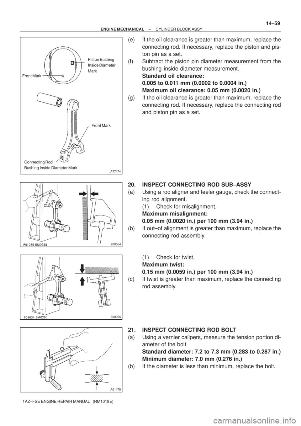
19. INSPECT PISTON PIN OIL CLEARANCE
(a) Using a caliper gauge, measure the inside diameter of the
piston bushing.
Bushing inside diameter:
22.005 to 22.014 mm (0.8663 to 0.8667 in.)
(b) Using a micrometer, measure the piston pin diameter.
Piston pin diameter:
21.997 to 22.009 mm (0.8660 to 0.8665 in.)
(c) Using a caliper gauge, measure the inside diameter of the
connecting rod bushing.
Bushing inside diameter:
22.005 to 22.014 mm (0.8663 to 0.8667 in.)
(d) Subtract the piston pin diameter measurement from the
piton pin hole diameter measurement.
Standard oil clearance:
0.005 to 0.011 mm (0.0002 to 0.0004 in.)
Maximum oil clearance: 0.05 mm (0.0020 in.)
Page 3483 of 5135
A77474
Piston Bushing
Inside Diameter
Mark
Front Mark
Connecting Rod
Bushing Inside Diameter MarkFront Mark
Z00064
Z00065
A01470
± ENGINE MECHANICALCYLINDER BLOCK ASSY
14±59
1AZ±FSE ENGINE REPAIR MANUAL (RM1019E)
(e) If the oil clearance is greater than maximum, replace the
connecting rod. If necessary, replace the piston and pis-
ton pin as a set.
(f) Subtract the piston pin diameter measurement from the
bushing inside diameter measurement.
Standard oil clearance:
0.005 to 0.011 mm (0.0002 to 0.0004 in.)
Maximum oil clearance: 0.05 mm (0.0020 in.)
(g) If the oil clearance is greater than maximum, replace the
connecting rod. If necessary, replace the connecting rod
and piston pin as a set.
20. INSPECT CONNECTING ROD SUB±ASSY
(a) Using a rod aligner and feeler gauge, check the connect-
ing rod alignment.
(1) Check for misalignment.
Maximum misalignment:
0.05 mm (0.0020 in.) per 100 mm (3.94 in.)
(b) If out±of alignment is greater than maximum, replace the
connecting rod assembly.
(1) Check for twist.
Maximum twist:
0.15 mm (0.0059 in.) per 100 mm (3.94 in.)
(c) If twist is greater than maximum, replace the connecting
rod assembly.
21. INSPECT CONNECTING ROD BOLT
(a) Using a vernier calipers, measure the tension portion di-
ameter of the bolt.
Standard diameter: 7.2 to 7.3 mm (0.283 to 0.287 in.)
Minimum diameter: 7.0 mm (0.276 in.)
(b) If the diameter is less than minimum, replace the bolt.
Page 3485 of 5135
A77273
Upper SideBottom Side
{mm} 6 (Ring Pin A)
5 (Ring Pin B)
A53029
A77274
Plastigage
± ENGINE MECHANICALCYLINDER BLOCK ASSY
14±61
1AZ±FSE ENGINE REPAIR MANUAL (RM1019E)
24. INSTALL RING PIN
(a) Using a plastic±faced hammer, tap into the ring pin.
Standard protrusion:
Ring pin A 6 mm (0.236 in.)
Ring pin B 5 mm (0.197 in.)
25. INSPECT CRANKSHAFT OIL CLEARANCE
NOTICE:
�Clean the backside of the bearing and the bearing
surface of the bearing cap and keep them free of oils.
�The bearing cap bolts are tightened in 2 progressive
steps.
(a) Clean each main journal and bearing.
(b) Install the upper bearing with an oil groove on cylinder
block.
(c) Install the lower bearing on the bearing cap sub assem-
bly.
(d) Place the crankshaft on the cylinder block.
(e) Lay a strip of Plastigage across each journal.
SST 09011±38121
Page 3486 of 5135
A77275Front Mark and Journal Number
A77475
����
10 � � � �
A77470
90�
Engine FrontPaint
Mark
A13855
14±62
± ENGINE MECHANICALCYLINDER BLOCK ASSY
1AZ±FSE ENGINE REPAIR MANUAL (RM1019E)
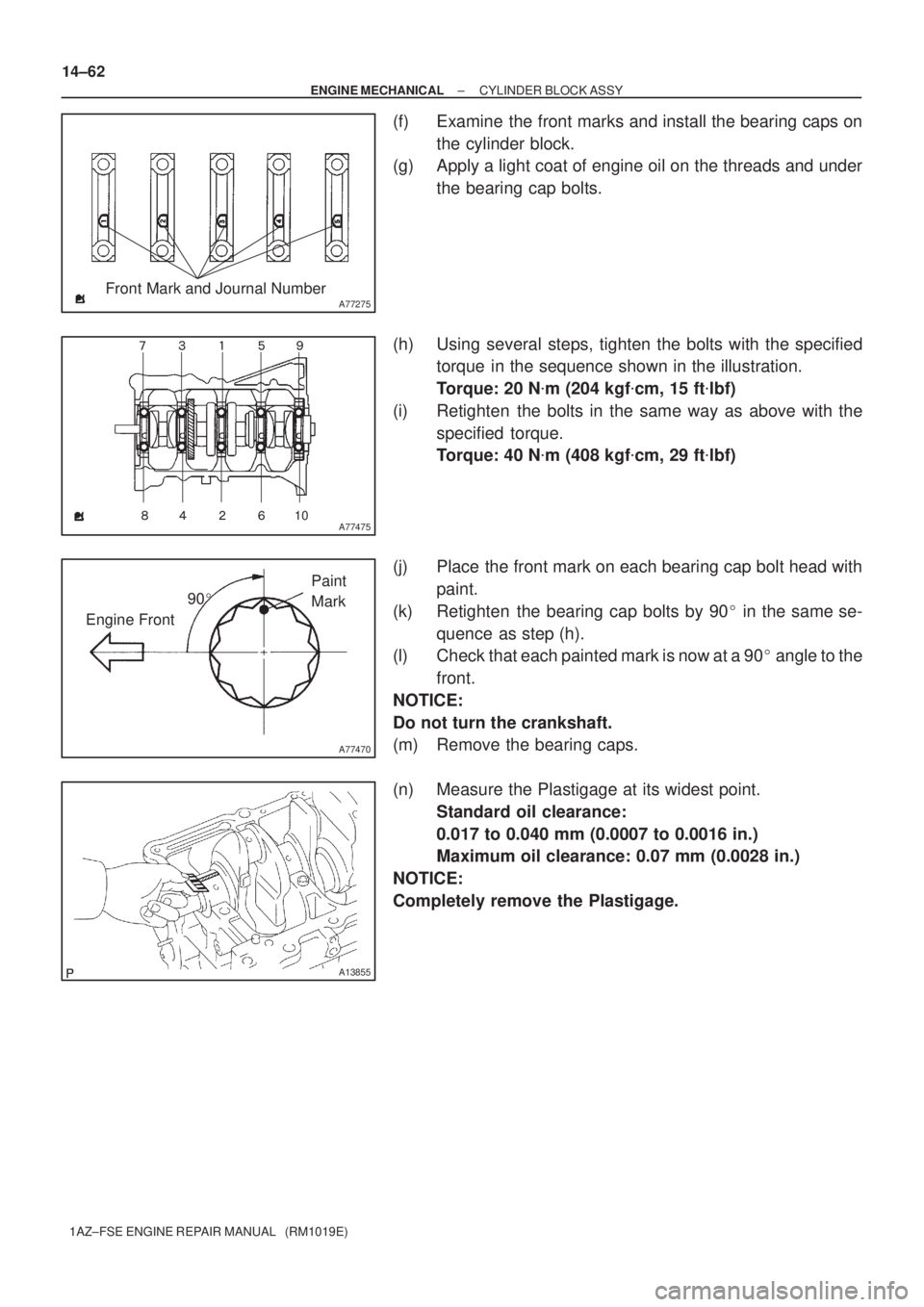
(f) Examine the front marks and install the bearing caps on
the cylinder block.
(g) Apply a light coat of engine oil on the threads and under
the bearing cap bolts.
(h) Using several steps, tighten the bolts with the specified
torque in the sequence shown in the illustration.
Torque: 20 N�m (204 kgf�cm, 15 ft�lbf)
(i) Retighten the bolts in the same way as above with the
specified torque.
Torque: 40 N�m (408 kgf�cm, 29 ft�lbf)
(j) Place the front mark on each bearing cap bolt head with
paint.
(k) Retighten the bearing cap bolts by 90� in the same se-
quence as step (h).
(l) Check that each painted mark is now at a 90� angle to the
front.
NOTICE:
Do not turn the crankshaft.
(m) Remove the bearing caps.
(n) Measure the Plastigage at its widest point.
Standard oil clearance:
0.017 to 0.040 mm (0.0007 to 0.0016 in.)
Maximum oil clearance: 0.07 mm (0.0028 in.)
NOTICE:
Completely remove the Plastigage.