Page 3592 of 5135
9808M±01
98±2
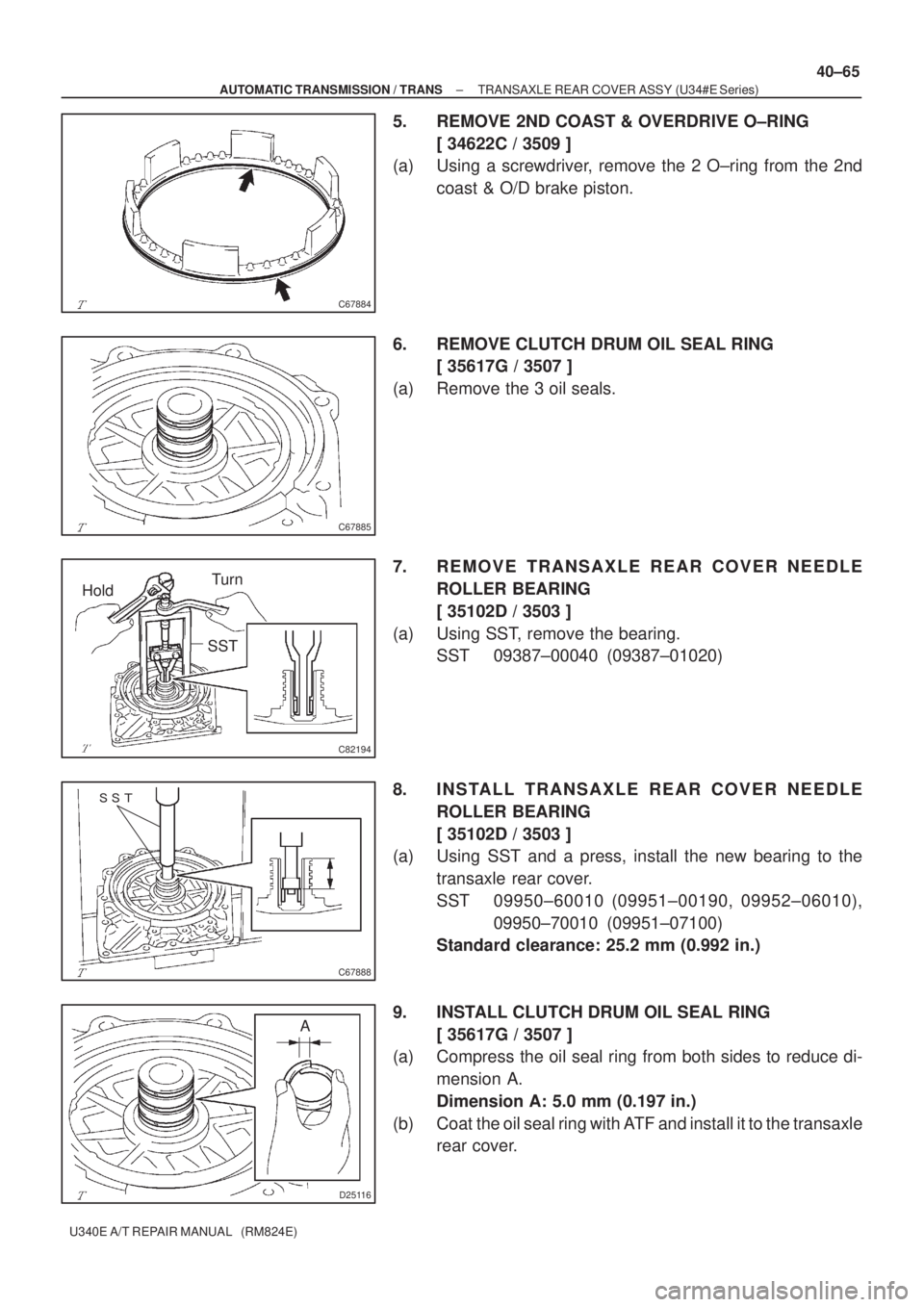
± COMPONENTS151350
3502/TORQUE CONVERTER, FRONT OIL PUMP & CHAIN (ATM)
(0008± )NZE121..ATM U340E
Page 3605 of 5135

C67884
C67885
HoldTurn
SST
C82194
���
C67888
D25116
A
± AUTOMATIC TRANSMISSION / TRANSTRANSAXLE REAR COVER ASSY (U34#E Series)
40±65
U340E A/T REPAIR MANUAL (RM824E)
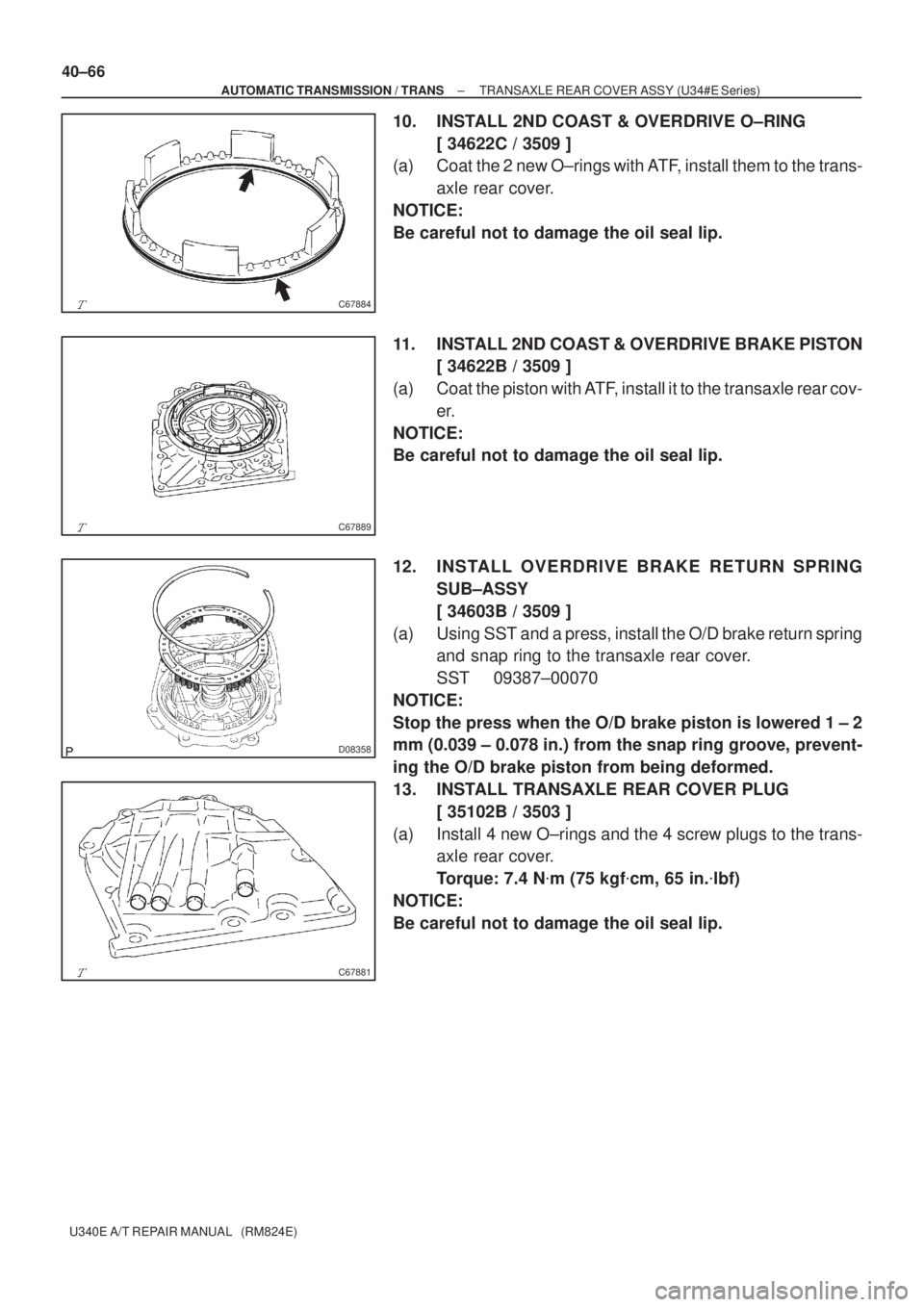
5. REMOVE 2ND COAST & OVERDRIVE O±RING
[ 34622C / 3509 ]
(a) Using a screwdriver, remove the 2 O±ring from the 2nd
coast & O/D brake piston.
6. REMOVE CLUTCH DRUM OIL SEAL RING
[ 35617G / 3507 ]
(a) Remove the 3 oil seals.
7. REMOVE TRANSAXLE REAR COVER NEEDLE
ROLLER BEARING
[ 35102D / 3503 ]
(a) Using SST, remove the bearing.
SST 09387±00040 (09387±01020)
8. INSTALL TRANSAXLE REAR COVER NEEDLE
ROLLER BEARING
[ 35102D / 3503 ]
(a) Using SST and a press, install the new bearing to the
transaxle rear cover.
SST 09950±60010 (09951±00190, 09952±06010),
09950±70010 (09951±07100)
Standard clearance: 25.2 mm (0.992 in.)
9. INSTALL CLUTCH DRUM OIL SEAL RING
[ 35617G / 3507 ]
(a) Compress the oil seal ring from both sides to reduce di-
mension A.
Dimension A: 5.0 mm (0.197 in.)
(b) Coat the oil seal ring with ATF and install it to the transaxle
rear cover.
Page 3606 of 5135

C67884
C67889
D08358
C67881
40±66
± AUTOMATIC TRANSMISSION / TRANSTRANSAXLE REAR COVER ASSY (U34#E Series)
U340E A/T REPAIR MANUAL (RM824E)
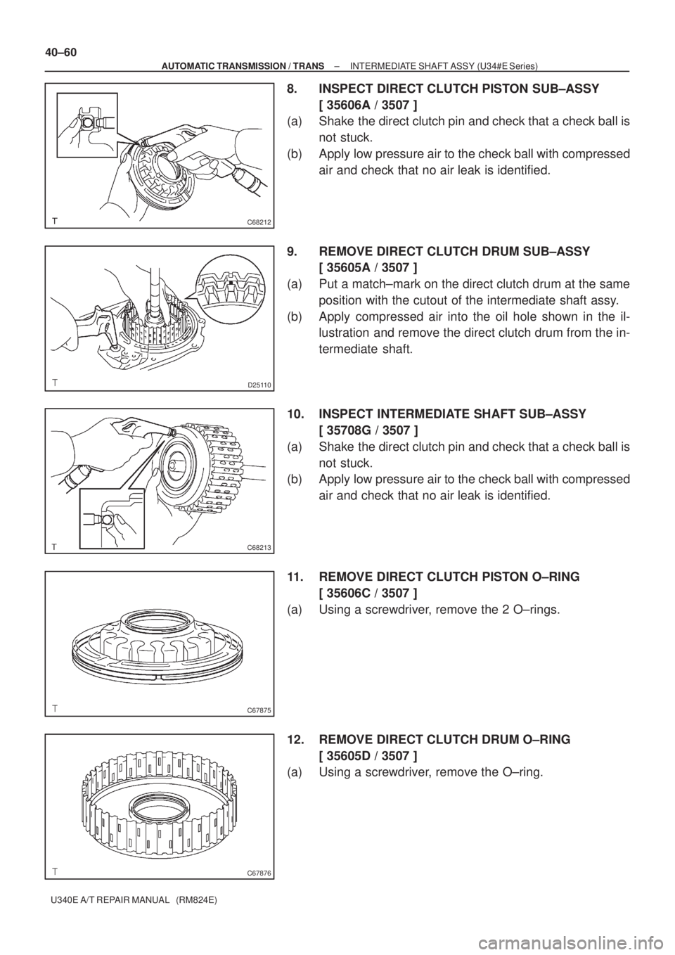
10. INSTALL 2ND COAST & OVERDRIVE O±RING
[ 34622C / 3509 ]
(a) Coat the 2 new O±rings with ATF, install them to the trans-
axle rear cover.
NOTICE:
Be careful not to damage the oil seal lip.
11. INSTALL 2ND COAST & OVERDRIVE BRAKE PISTON
[ 34622B / 3509 ]
(a) Coat the piston with ATF, install it to the transaxle rear cov-
er.
NOTICE:
Be careful not to damage the oil seal lip.
12. INSTALL OVERDRIVE BRAKE RETURN SPRING
SUB±ASSY
[ 34603B / 3509 ]
(a) Using SST and a press, install the O/D brake return spring
and snap ring to the transaxle rear cover.
SST 09387±00070
NOTICE:
Stop the press when the O/D brake piston is lowered 1 ± 2
mm (0.039 ± 0.078 in.) from the snap ring groove, prevent-
ing the O/D brake piston from being deformed.
13. INSTALL TRANSAXLE REAR COVER PLUG
[ 35102B / 3503 ]
(a) Install 4 new O±rings and the 4 screw plugs to the trans-
axle rear cover.
Torque: 7.4 N�m (75 kgf�cm, 65 in.�lbf)
NOTICE:
Be careful not to damage the oil seal lip.
Page 3609 of 5135

C68212
D25110
C68213
C67875
C67876
40±60
± AUTOMATIC TRANSMISSION / TRANSINTERMEDIATE SHAFT ASSY (U34#E Series)
U340E A/T REPAIR MANUAL (RM824E)
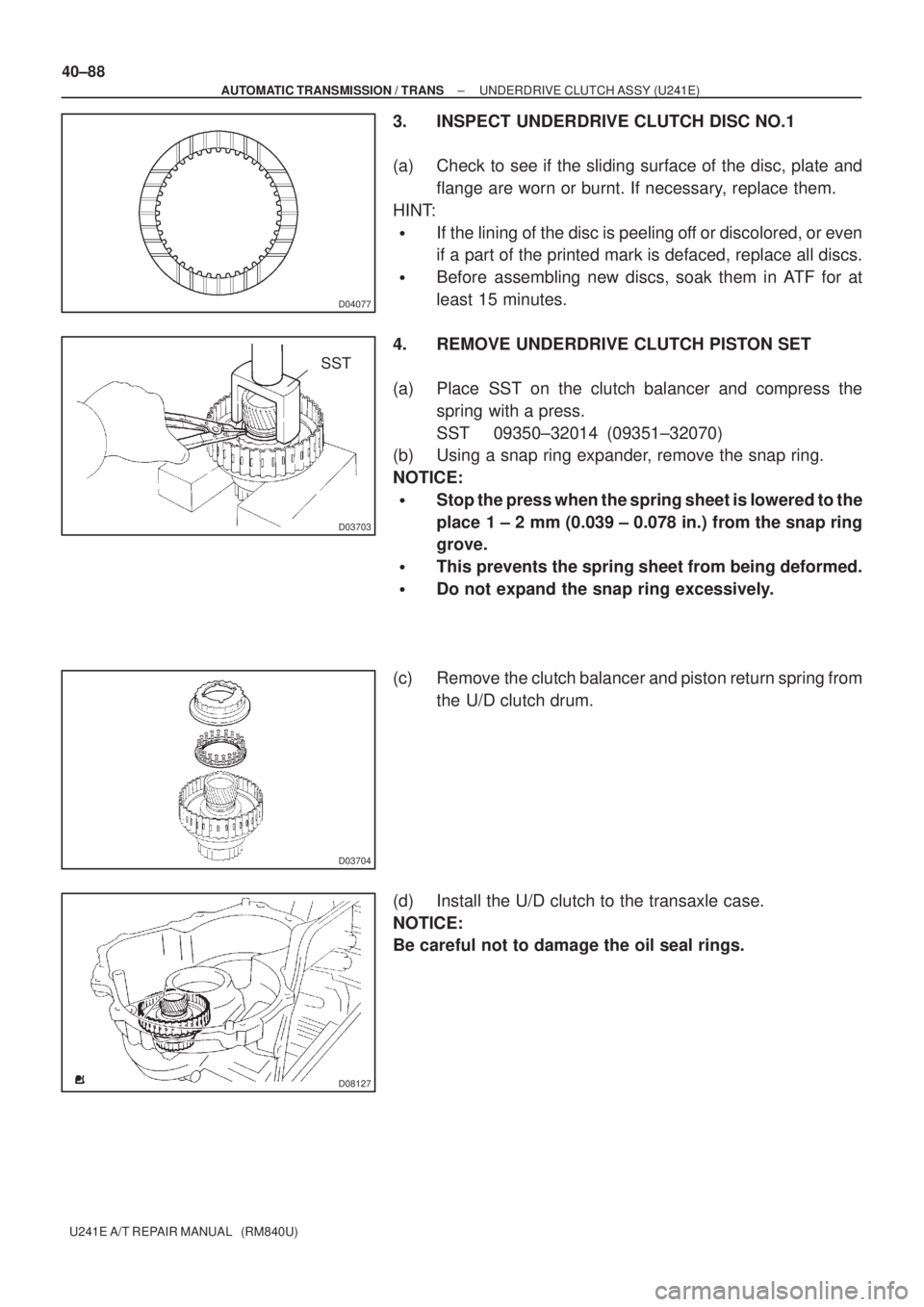
8. INSPECT DIRECT CLUTCH PISTON SUB±ASSY
[ 35606A / 3507 ]
(a) Shake the direct clutch pin and check that a check ball is
not stuck.
(b) Apply low pressure air to the check ball with compressed
air and check that no air leak is identified.
9. REMOVE DIRECT CLUTCH DRUM SUB±ASSY
[ 35605A / 3507 ]
(a) Put a match±mark on the direct clutch drum at the same
position with the cutout of the intermediate shaft assy.
(b) Apply compressed air into the oil hole shown in the il-
lustration and remove the direct clutch drum from the in-
termediate shaft.
10. INSPECT INTERMEDIATE SHAFT SUB±ASSY
[ 35708G / 3507 ]
(a) Shake the direct clutch pin and check that a check ball is
not stuck.
(b) Apply low pressure air to the check ball with compressed
air and check that no air leak is identified.
11. REMOVE DIRECT CLUTCH PISTON O±RING
[ 35606C / 3507 ]
(a) Using a screwdriver, remove the 2 O±rings.
12. REMOVE DIRECT CLUTCH DRUM O±RING
[ 35605D / 3507 ]
(a) Using a screwdriver, remove the O±ring.
Page 3624 of 5135
4006T±01
D08123
D08124
D08125
D08126
± AUTOMATIC TRANSMISSION / TRANSUNDERDRIVE CLUTCH ASSY (U241E)
40±87
U241E A/T REPAIR MANUAL (RM840U)
UNDERDRIVE CLUTCH ASSY (U241E)
OVERHAUL
1. INSPECT UNDERDRIVE PACK CLEARANCE
(a) Inspect the U/D clutch to the transaxle case.
NOTICE:
Be careful not to damage the oil seal rings.
(b) Install a dial indicator as shown in the illustration.
(c) Measure the U/D clutch pack clearance while applying
and releasing compressed air (392 kPa, 4.0 kgf/cm
2, 57
psi).
Pack clearance: 1.51 ± 1.90 mm (0.0594 ± 0.0748 in.)
If the pack clearance is non±standard, inspect the discs, plates
and flange.
2. REMOVE UNDERDRIVE CLUTCH DISC NO.1
(a) Using a screwdriver, remove the snap ring.
(b) Remove the flange, 3 discs and 3 plates from the U/D
clutch drum.
Page 3625 of 5135

D04077
D03703
SST
D03704
D08127
40±88
± AUTOMATIC TRANSMISSION / TRANSUNDERDRIVE CLUTCH ASSY (U241E)
U241E A/T REPAIR MANUAL (RM840U)
3. INSPECT UNDERDRIVE CLUTCH DISC NO.1
(a) Check to see if the sliding surface of the disc, plate and
flange are worn or burnt. If necessary, replace them.
HINT:
�If the lining of the disc is peeling off or discolored, or even
if a part of the printed mark is defaced, replace all discs.
�Before assembling new discs, soak them in ATF for at
least 15 minutes.
4. REMOVE UNDERDRIVE CLUTCH PISTON SET
(a) Place SST on the clutch balancer and compress the
spring with a press.
SST 09350±32014 (09351±32070)
(b) Using a snap ring expander, remove the snap ring.
NOTICE:
�Stop the press when the spring sheet is lowered to the
place 1 ± 2 mm (0.039 ± 0.078 in.) from the snap ring
grove.
�This prevents the spring sheet from being deformed.
�Do not expand the snap ring excessively.
(c) Remove the clutch balancer and piston return spring from
the U/D clutch drum.
(d) Install the U/D clutch to the transaxle case.
NOTICE:
Be careful not to damage the oil seal rings.
Page 3628 of 5135
D08125
D08123
D08124
± AUTOMATIC TRANSMISSION / TRANSUNDERDRIVE CLUTCH ASSY (U241E)
40±91
U241E A/T REPAIR MANUAL (RM840U)
(b) Using a screwdriver, install the snap ring.
(c) Check that the end gap of the snap ring is not aligned with
one of the cutouts.
11. INSPECT UNDERDRIVE PACK CLEARANCE
(a) Install the U/D clutch to the transaxle case.
NOTICE:
Be careful not to damage the oil seal rings.
(b) Set a dial indicator as shown in the illustration.
(c) Measure the U/D clutch piston stroke while applying and
releasing compressed air (392 kPa, 4.0 kgf/cm
2, 57 psi).
Park clearance: 1.51 ± 1.90 mm (0.0594 ± 0.0748 in.)
If the pack clearance is less than the minimum, parts may have
been assembled incorrectly, so check and reassemble again.
If the park clearance is non±standard, select another flange.
HINT:
There are 3 flanges in different thickness.
Flange thickness: mm (in.)
No.ThicknessNo.Thickness
A3.0 (0.118)C3.4 (0.134)
B3.2 (0.126)±±
Page 3637 of 5135
C83143
C83144
C83142
D03900
D03900
± AUTOMATIC TRANSMISSION / TRANSAUTOMATIC TRANSAXLE ASSY (U241E)
40±15
U241E A/T REPAIR MANUAL (RM840U)
4. REMOVE OIL COOLER TUBE UNION(INLET OIL
COOLER UNION)
(a) Remove the union.
(b) Remove the O±ring from the union.
5. REMOVE OIL COOLER TUBE UNION(OUTLET OIL
COOLER UNION)
(a) Remove the elbow.
(b) Remove the O±ring from the elbow.
6. REMOVE TRANSAXLE CASE NO.1 PLUG
(a) Remove the 4 transaxle case No. 1 plugs from the trans-
axle case.
(b) Remove 4 O±rings from the 4 transaxle case No. 1 plugs.
7. REMOVE SPEED SENSOR(TMC ±MADE)
(a) Remove the 2 bolts and the 2 speed sensors from the
transaxle assy.
(b) Remove the 2 O±rings from the sensors.
8. REMOVE TRANSMISSION REVOLUTION
SENSOR(AISIN ±MADE)
(a) Remove the 2 bolts and the 2 transmission revolution
sensors from the transaxle assy.
(b) Remove the 2 O±rings from the sensors.