Page 1322 of 5135
������
������ ������H40990
DLC3DTC B0116/48
TC
CG
Side Squib LH
Airbag
Sensor
Assy
Center
DC
±
DIAGNOSTICS SUPPLEMENTAL RESTRAINT SYSTEM
05±1243
AVENSIS REPAIR MANUAL (RM1018E)
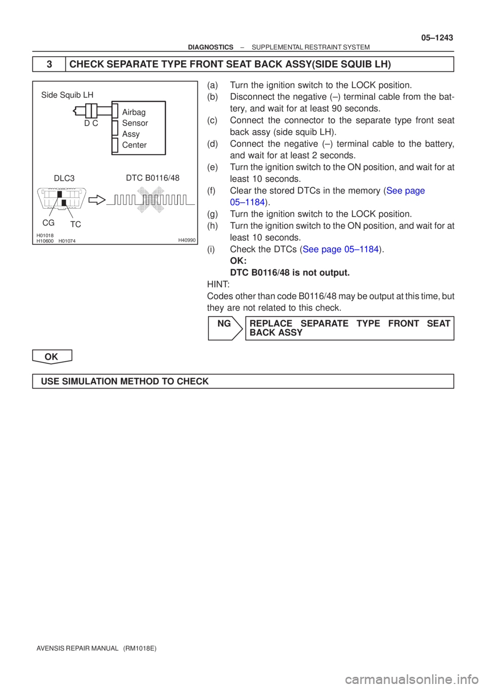
3 CHECK SEPARATE TYPE FRONT SEAT BACK ASSY(SIDE SQUIB LH)
(a) Turn the ignition switch to the LOCK position.
(b) Disconnect the negative (±) terminal cable from the bat-
tery, and wait for at least 90 seconds.
(c) Connect the connector to the separate type front seat back assy (side squib LH).
(d) Connect the negative (±) terminal cable to the battery, and wait for at least 2 seconds.
(e) Turn the ignition switch to the ON position, and wait for at least 10 seconds.
(f)Clear the stored DTCs in the memory (See page 05±1184).
(g) Turn the ignition switch to the LOCK position.
(h) Turn the ignition switch to the ON position, and wait for at least 10 seconds.
(i)Check the DTCs (See page 05±1184). OK:
DTC B0116/48 is not output.
HINT:
Codes other than code B0116/48 may be output at this time, but
they are not related to this check.
NG REPLACE SEPARATE TYPE FRONT SEAT BACK ASSY
OK
USE SIMULATION METHOD TO CHECK
Page 1324 of 5135
�����
�\b���
�����
�����H42129
Curtain Shield
Squib RHAirbag
Sensor
Assy
Center
DLC3
CGTC DTC B1161/84
Floor Wire No.2
Service Wire
ICR+
ICR±
C
D
05±1326
±
DIAGNOSTICS SUPPLEMENTAL RESTRAINT SYSTEM
AVENSIS REPAIR MANUAL (RM1018E)
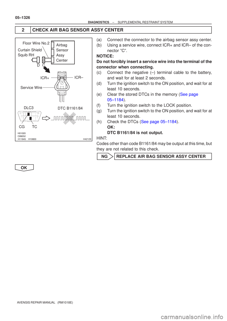
2CHECK AIR BAG SENSOR ASSY CENTER
(a)Connect the connector to the airbag sensor assy center.
(b)Using a service wire, connect ICR+ and ICR± of the con- nector ºCº.
NOTICE:
Do not forcibly insert a service wire into the terminal of the
connector when connecting.
(c)Connect the negative (±) terminal cable to the battery, and wait for at least 2 seconds.
(d)Turn the ignition switch to the ON position, and wait for at least 10 seconds.
(e)Clear the stored DTCs in the memory (See page
05±1184).
(f) Turn the ignition switch to the LOCK position.
(g) Turn the ignition switch to the ON position, and wait for at least 10 seconds.
(h)Check the DTCs (See page 05±1184).
OK:
DTC B1161/84 is not output.
HINT:
Codes other than code B1161/84 may be output at this time, but
they are not related to this check.
NG REPLACE AIR BAG SENSOR ASSY CENTER
OK
Page 1325 of 5135
������
������ ������H40933
Airbag
Sensor
Assy
Center
Curtain Shield
Squib RH
DLC3
TC
CG
DTC B1161/84
C
D
±
DIAGNOSTICS SUPPLEMENTAL RESTRAINT SYSTEM
05±1327
AVENSIS REPAIR MANUAL (RM1018E)
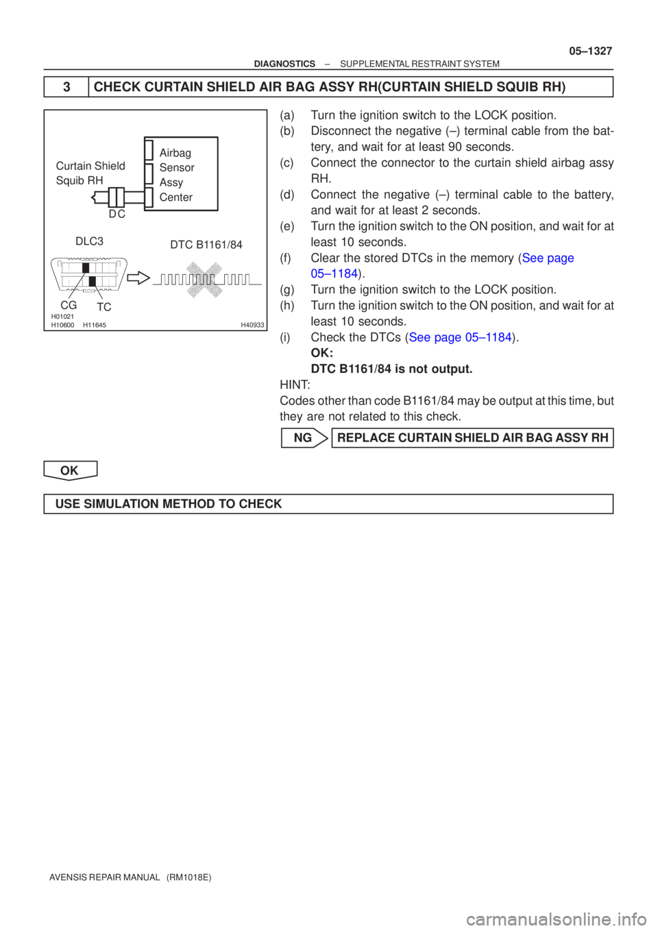
3 CHECK CURTAIN SHIELD AIR BAG ASSY RH(CURTAIN SHIELD SQUIB RH)
(a) Turn the ignition switch to the LOCK position.
(b) Disconnect the negative (±) terminal cable from the bat-
tery, and wait for at least 90 seconds.
(c) Connect the connector to the curtain shield airbag assy RH.
(d) Connect the negative (±) terminal cable to the battery, and wait for at least 2 seconds.
(e) Turn the ignition switch to the ON position, and wait for at least 10 seconds.
(f)Clear the stored DTCs in the memory (See page 05±1184).
(g) Turn the ignition switch to the LOCK position.
(h) Turn the ignition switch to the ON position, and wait for at least 10 seconds.
(i)Check the DTCs (See page 05±1184). OK:
DTC B1161/84 is not output.
HINT:
Codes other than code B1161/84 may be output at this time, but
they are not related to this check.
NG REPLACE CURTAIN SHIELD AIR BAG ASSY RH
OK
USE SIMULATION METHOD TO CHECK
Page 1328 of 5135
������
������������H40956
Curtain Shield
Squib RHDLC3
TC
CG
DTC B1160/83
Airbag
Sensor
Assy
Center
C
D
������
������������H40931
Airbag
Sensor
Assy
Center
Curtain Shield
Squib RH
DLC3
TC
CG
DTC B1160/83
C
D
05±1324
±
DIAGNOSTICS SUPPLEMENTAL RESTRAINT SYSTEM
AVENSIS REPAIR MANUAL (RM1018E)
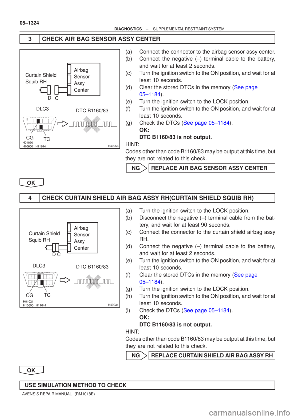
3CHECK AIR BAG SENSOR ASSY CENTER
(a)Connect the connector to the airbag sensor assy center.
(b)Connect the negative (±) terminal cable to the battery, and wait for at least 2 seconds.
(c)Turn the ignition switch to the ON position, and wait for at least 10 seconds.
(d)Clear the stored DTCs in the memory (See page 05±1184).
(e)Turn the ignition switch to the LOCK position.
(f)Turn the ignition switch to the ON position, and wait for at least 10 seconds.
(g)Check the DTCs (See page 05±1184).
OK:
DTC B1160/83 is not output.
HINT:
Codes other than code B1160/83 may be output at this time, but
they are not related to this check.
NGREPLACE AIR BAG SENSOR ASSY CENTER
OK
4CHECK CURTAIN SHIELD AIR BAG ASSY RH(CURTAIN SHIELD SQUIB RH)
(a)Turn the ignition switch to the LOCK position.
(b)Disconnect the negative (±) terminal cable from the bat- tery, and wait for at least 90 seconds.
(c)Connect the connector to the curtain shield airbag assy RH.
(d)Connect the negative (±) terminal cable to the battery, and wait for at least 2 seconds.
(e)Turn the ignition switch to the ON position, and wait for at least 10 seconds.
(f)Clear the stored DTCs in the memory (See page 05±1184).
(g) Turn the ignition switch to the LOCK position.
(h) Turn the ignition switch to the ON position, and wait for at
least 10 seconds.
(i)Check the DTCs (See page 05±1184). OK:
DTC B1160/83 is not output.
HINT:
Codes other than code B1160/83 may be output at this time, but
they are not related to this check.
NG REPLACE CURTAIN SHIELD AIR BAG ASSY RH
OK
USE SIMULATION METHOD TO CHECK
Page 1330 of 5135
����� \b�\b�\b
�����H42843
Airbag
Sensor
Assy
Rear LHSide
Airbag
Sensor
Assy LH
DLC3
CG TC
DTC B1155/39
05±1318
±
DIAGNOSTICS SUPPLEMENTAL RESTRAINT SYSTEM
AVENSIS REPAIR MANUAL (RM1018E)
INSPECTION PROCEDURE
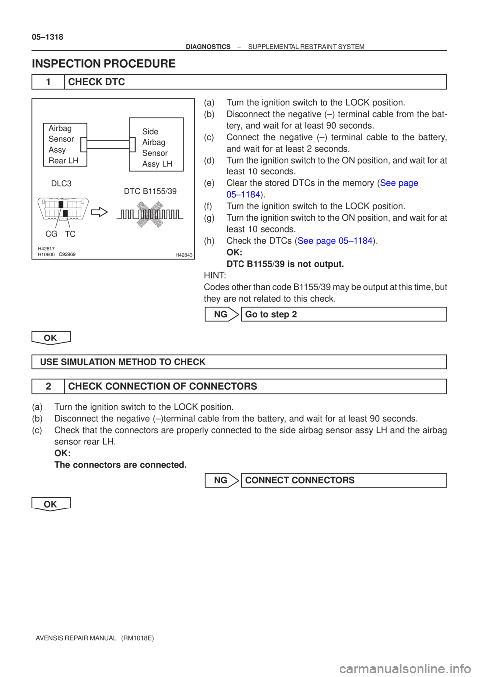
1CHECK DTC
(a)Turn the ignition switch to the LOCK position.
(b)Disconnect the negative (±) terminal cable from the bat- tery, and wait for at least 90 seconds.
(c)Connect the negative (±) terminal cable to the battery, and wait for at least 2 seconds.
(d)Turn the ignition switch to the ON position, and wait for at least 10 seconds.
(e)Clear the stored DTCs in the memory (See page 05±1184).
(f) Turn the ignition switch to the LOCK position.
(g) Turn the ignition switch to the ON position, and wait for at least 10 seconds.
(h)Check the DTCs (See page 05±1184). OK:
DTC B1155/39 is not output.
HINT:
Codes other than code B1155/39 may be output at this time, but
they are not related to this check.
NG Go to step 2
OK
USE SIMULATION METHOD TO CHECK
2 CHECK CONNECTION OF CONNECTORS
(a) Turn the ignition switch to the LOCK position.
(b) Disconnect the negative (±)terminal cable from the battery, and wait for at least 90 seconds.
(c) Check that the connectors are properly connected to the side airbag sensor as\
sy LH and the airbag sensor rear LH.
OK:
The connectors are connected.
NG CONNECT CONNECTORS
OK
Page 1335 of 5135
����� \b�\b��
�����H42841
Side
Airbag
Sensor
Assy RH
DLC3
CG TC DTC B1154/38Airbag
Sensor
Rear RH
±
DIAGNOSTICS SUPPLEMENTAL RESTRAINT SYSTEM
05±1313
AVENSIS REPAIR MANUAL (RM1018E)
INSPECTION PROCEDURE
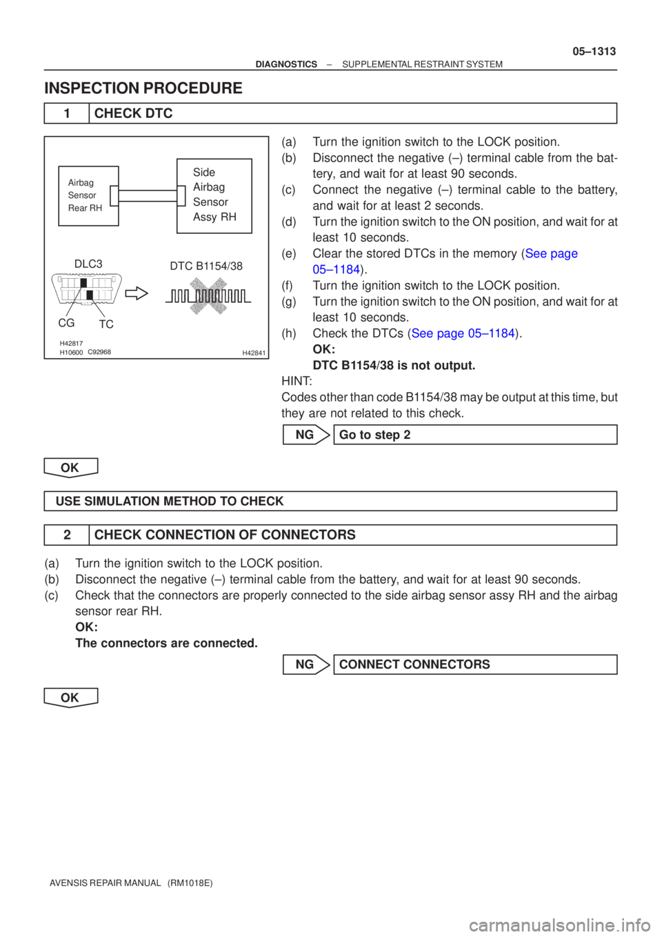
1CHECK DTC
(a)Turn the ignition switch to the LOCK position.
(b)Disconnect the negative (±) terminal cable from the bat-
tery, and wait for at least 90 seconds.
(c)Connect the negative (±) terminal cable to the battery, and wait for at least 2 seconds.
(d)Turn the ignition switch to the ON position, and wait for at least 10 seconds.
(e)Clear the stored DTCs in the memory (See page 05±1184).
(f) Turn the ignition switch to the LOCK position.
(g) Turn the ignition switch to the ON position, and wait for at least 10 seconds.
(h)Check the DTCs (See page 05±1184). OK:
DTC B1154/38 is not output.
HINT:
Codes other than code B1154/38 may be output at this time, but
they are not related to this check.
NG Go to step 2
OK
USE SIMULATION METHOD TO CHECK
2 CHECK CONNECTION OF CONNECTORS
(a) Turn the ignition switch to the LOCK position.
(b) Disconnect the negative (±) terminal cable from the battery, and wait for at least 90 seconds.
(c) Check that the connectors are properly connected to the side airbag sensor as\
sy RH and the airbag sensor rear RH.
OK:
The connectors are connected.
NG CONNECT CONNECTORS
OK
Page 1340 of 5135
����� �����\b�����H42526
Airbag
Sensor
Assy
Center
DLC3
Seat
Position
Airbag
Sensor
CGTC DTC B1153/25
Airbag
Sensor
Assy
Center
Seat
Position
Airbag
Sensor
LHD:
RHD:
±
DIAGNOSTICS SUPPLEMENTAL RESTRAINT SYSTEM
05±1305
AVENSIS REPAIR MANUAL (RM1018E)
INSPECTION PROCEDURE
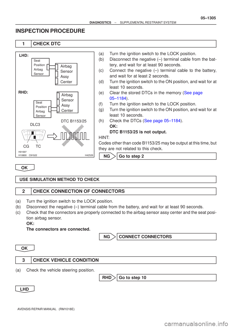
1CHECK DTC
(a)Turn the ignition switch to the LOCK position.
(b)Disconnect the negative (±) terminal cable from the bat-
tery, and wait for at least 90 seconds.
(c)Connect the negative (±) terminal cable to the battery,
and wait for at least 2 seconds.
(d)Turn the ignition switch to the ON position, and wait for at least 10 seconds.
(e)Clear the stored DTCs in the memory (See page
05±1184).
(f) Turn the ignition switch to the LOCK position.
(g) Turn the ignition switch to the ON position, and wait for at least 10 seconds.
(h)Check the DTCs (See page 05±1184).
OK:
DTC B1153/25 is not output.
HINT:
Codes other than code B1153/25 may be output at this time, but
they are not related to this check.
NG Go to step 2
OK
USE SIMULATION METHOD TO CHECK
2 CHECK CONNECTION OF CONNECTORS
(a) Turn the ignition switch to the LOCK position.
(b) Disconnect the negative (±) terminal cable from the battery, and wait for at least 90 seconds.
(c) Check that the connectors are properly connected to the airbag sensor assy center and the seat posi- tion airbag sensor.
OK:
The connectors are connected.
NG CONNECT CONNECTORS
OK
3 CHECK VEHICLE CONDITION
(a) Check the vehicle steering position. RHD Go to step 10
LHD
Page 1342 of 5135
\f�����
� ����H42231
Airbag
Sensor
Assy
Center
LSP+ LSP±
Floor Wire
Seat Position
Airbag Sensor A
B
C
D
\f������
����\f����\bH42468
DLC3
CGTC
Airbag
Sensor
Assy
Center
Seat
Position
Airbag
Sensor
DTC B1153/25
±
DIAGNOSTICS SUPPLEMENTAL RESTRAINT SYSTEM
05±1307
AVENSIS REPAIR MANUAL (RM1018E)
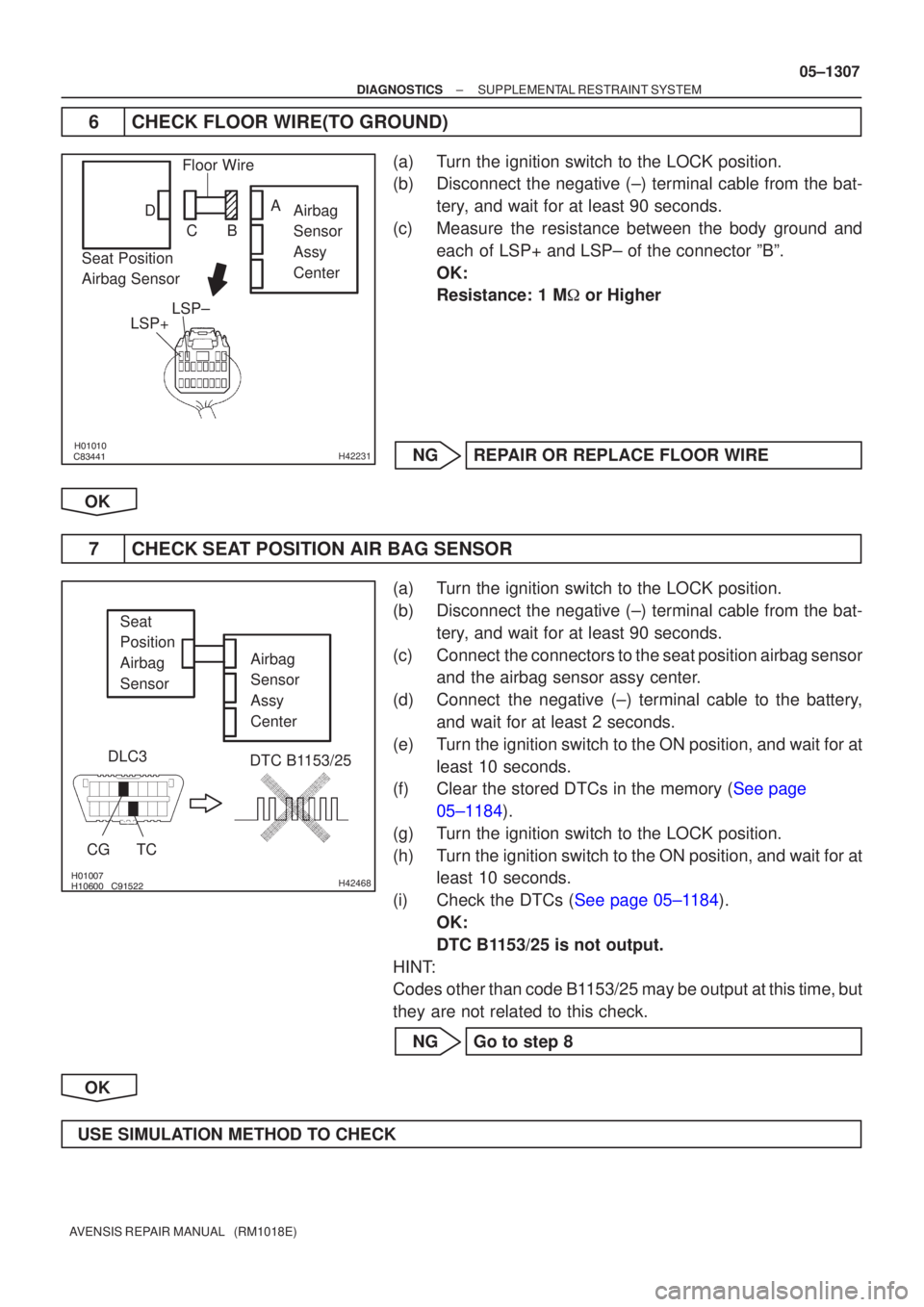
6CHECK FLOOR WIRE(TO GROUND)
(a)Turn the ignition switch to the LOCK position.
(b)Disconnect the negative (±) terminal cable from the bat-
tery, and wait for at least 90 seconds.
(c)Measure the resistance between the body ground and each of LSP+ and LSP± of the connector ºBº.
OK:
Resistance: 1 M � or Higher
NGREPAIR OR REPLACE FLOOR WIRE
OK
7CHECK SEAT POSITION AIR BAG SENSOR
(a)Turn the ignition switch to the LOCK position.
(b)Disconnect the negative (±) terminal cable from the bat- tery, and wait for at least 90 seconds.
(c)Connect the connectors to the seat position airbag sensor and the airbag sensor assy center.
(d)Connect the negative (±) terminal cable to the battery, and wait for at least 2 seconds.
(e)Turn the ignition switch to the ON position, and wait for at least 10 seconds.
(f)Clear the stored DTCs in the memory (See page
05±1184).
(g) Turn the ignition switch to the LOCK position.
(h) Turn the ignition switch to the ON position, and wait for at least 10 seconds.
(i)Check the DTCs (See page 05±1184). OK:
DTC B1153/25 is not output.
HINT:
Codes other than code B1153/25 may be output at this time, but
they are not related to this check.
NG Go to step 8
OK
USE SIMULATION METHOD TO CHECK