Page 515 of 5135
± DIAGNOSTICSSFI SYSTEM (1AZ±FSE)
05±415
AVENSIS REPAIR MANUAL (RM1018E)
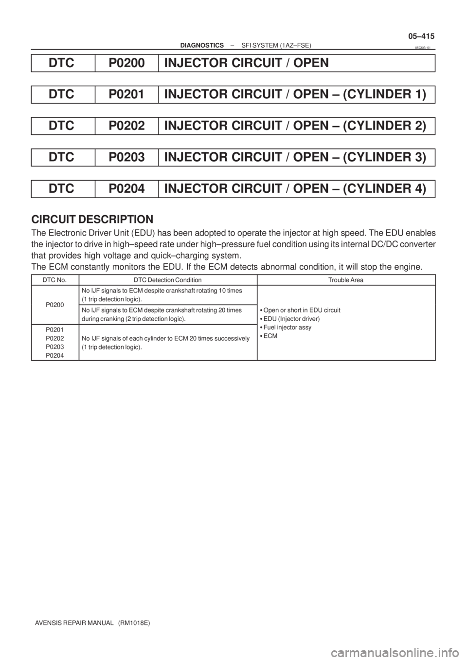
DTC P0200 INJECTOR CIRCUIT / OPEN
DTC P0201 INJECTOR CIRCUIT / OPEN ± (CYLINDER 1)
DTC P0202 INJECTOR CIRCUIT / OPEN ± (CYLINDER 2)
DTC P0203 INJECTOR CIRCUIT / OPEN ± (CYLINDER 3)
DTC P0204 INJECTOR CIRCUIT / OPEN ± (CYLINDER 4)
CIRCUIT DESCRIPTION
The Electronic Driver Unit (EDU) has been adopted to operate the injector at high speed. The EDU enables
the injector to drive in high±speed rate under high±pressure fuel condition using its internal DC/DC converter
that provides high voltage and quick±charging system.
The ECM constantly monitors the EDU. If the ECM detects abnormal condition, it will stop the engine.
DTC No.DTC Detection ConditionTrouble Area
P0200
No IJF signals to ECM despite crankshaft rotating 10 times
(1 trip detection logic).
P0200No IJF signals to ECM despite crankshaft rotating 20 times
during cranking (2 trip detection logic).�Open or short in EDU circuit
�EDU (Injector driver)
P0201
P0202
P0203
P0204
No IJF signals of each cylinder to ECM 20 times successively
(1 trip detection logic).
(j )
�Fuel injector assy
�ECM
05CKG±01
Page 516 of 5135
A76865
ECM
+B 1
E9
W±B 4
2
1
2
12
4A
W±B
Battery
EC 1 3
5
FL MAINB±R
EE (Shielded) 4EFI
No. 1Engine
Room
R/B No. 4
B±W
B±R
Engine Room
R/B No. 4 EFI
Relay
B±Y 44
44
1
4B 1Engine Room
J/B No. 4 B±G
B±GEFI 1
1A 1Engine
Room
R/B No. 1
and
Engine
Room
J/B No. 1GRB±R B±R
B±YB±YB±YGRGR B±R
+B2 2
E9 D
J14
(LHD)(RHD)D
J28D
J14
(LHD)(RHD)D
J28
D
J14D
J28 J/C
B±R 2
IE4
(LHD) (RHD)3
IP1
7
IE3
(LHD) (RHD)7
IO12
IE1
B±YMREL 8
E9
BATT 3
E9
4 IE2V
IREL 35
E10 V
21 5
3INJ
Relay 44
44
R±B
IJF1 25
E13
G±W
#1 1
E13 5
E5
4
E5 IJF
IJT#1
W±R
#2 2
E13 1
E5 IJT#2
R±W
#3 3
E13 2
E5 IJT#3
W±L
#4 4
E13 3
E5 IJT#4
Electronic
Driver Unit
EA1 7Y4
E4 INJ#1
1
2 I 5
Injector No. 1
BR
B±R 3
E4 INJ#4
1
2 I 8
Injector No. 4
BR
BR 5
E4
COM1
P 1
E4 INJ#2
1
2 I 6
Injector No. 2
L
B±W 2
E4 INJ#3
1
2 I 7
Injector No. 3
L
L 6
E4 COM2 B
B (Shielded)
8
E4VB
W7
E4 GND
W±B
EF BR BR 05±416
± DIAGNOSTICSSFI SYSTEM (1AZ±FSE)
AVENSIS REPAIR MANUAL (RM1018E)
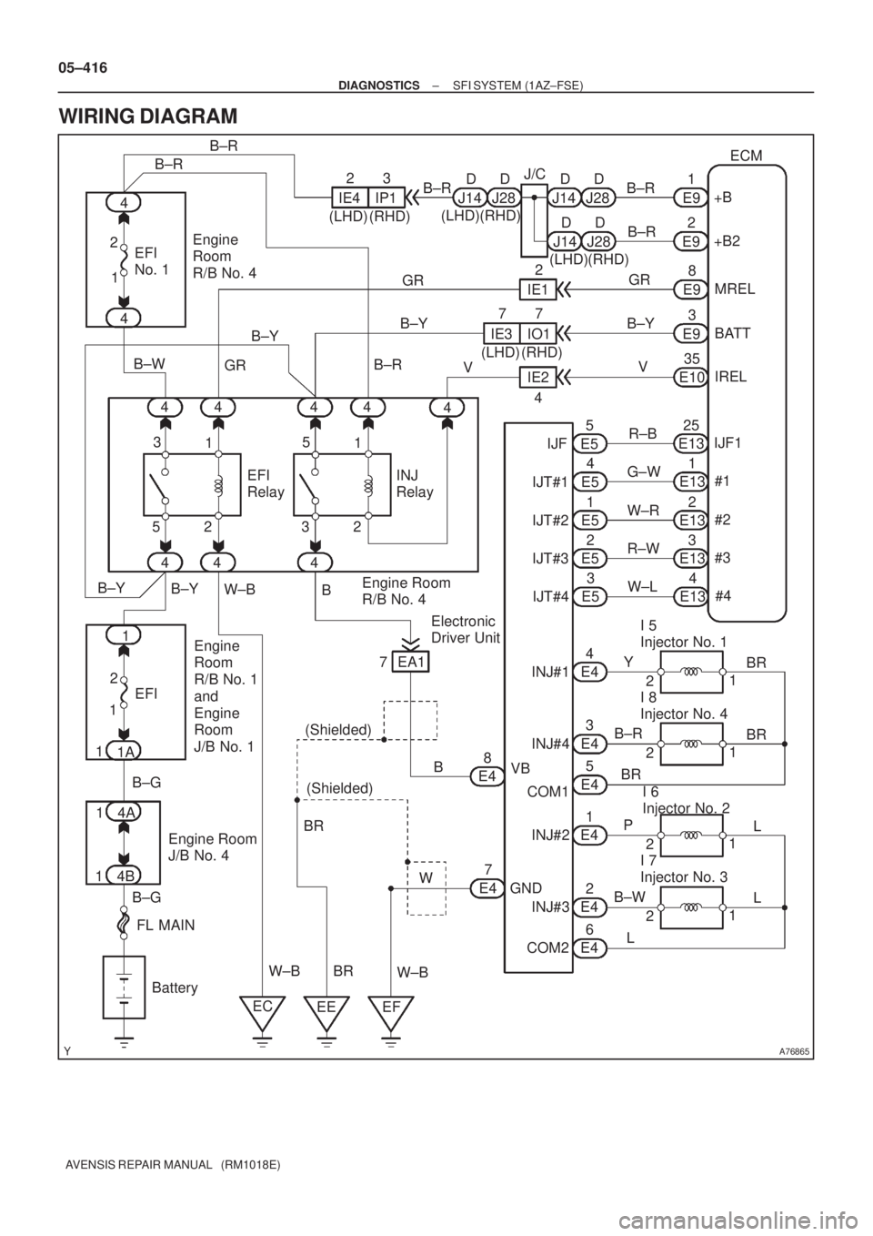
WIRING DIAGRAM
Page 4217 of 5135

05−136
− DIAGNOSTICSSFI SYSTEM (2AZ−FSE)
AVENSIS Supplement (RM1045E)
DTC P0200 INJECTOR CIRCUIT / OPEN
DTC P0201INJECTOR CIRCUIT / OPEN−(CYLINDER1)
DTC P0202 INJECTOR CIRCUIT / OPEN−(CYLINDER 2)
DTC P0203 INJECTOR CIRCUIT / OPEN−(CYLINDER 3)
DTC P0204 INJECTOR CIRCUIT / OPEN−(CYLINDER 4)
CIRCUIT DESCRIPTION
The Electronic Driver Unit (EDU) has been adopted to operate the injector at high speed. The EDU enables
the injector to drive in high−speed rate under high−pressure fuel condition using its internal DC/DC converter
that provides high voltage and quick−charging system.
The ECM constantly monitors the EDU. If the ECM detects abnormal condition, it will stop the engine.
DTC No.DTC Detection ConditionTrouble Area
P0200No IJF signals to ECM despite crankshaft rotating10 times
(1trip detection logic)
SOpen or short in EDU circuit
SEDU (Injector driver)
SFuel injector assy
SECM
P0200No IJF signals to ECM despite crankshaft rotating 20 times
during cranking (2 trip detection logic)
SOpen or short in EDU circuit
SEDU (Injector driver)
SFuel injector assy
SECM
P0201
P0202
P0203
P0204
No IJF signals of each cylinder to ECM 20 times successively
(1trip detection logic)
SOpen or short in EDU circuit
SEDU (Injector driver)
SFuel injector assy
SECM
05CKG−02
Page 4218 of 5135
A76865
ECM
+B 1
E9
W−B 4
2
1
2
12
4A
W−B
Battery
EC 1 3
5
FL MAINB−R
EE (Shielded) 4EFI
No.1Engine
Room
R/B No. 4
B−W
B−R
Engine Room
R/B No. 4 EFI
Relay
B−Y 44
44
1
4B 1Engine Room
J/B No. 4 B−G
B−G EFI 1
1A 1Engine
Room
R/B No.1 GRB−R B−R
B−YB−YB−Y GRGR B−R
+B2 2
E9 D
J14
(LHD)(RHD)D
J28D
J14
(LHD)(RHD)D
J28
D
J14D
J28 J/C
B−R 2
IE4
(LHD) (RHD)3
IP1
7
IE3
(LHD) (RHD)7
IO1 2
IE1
B−YMREL 8
E9
BATT 3
E9
4 IE2V
IREL 35
E10 V
21 5
3INJ
Relay 44
44
R−B
IJF1 25
E13
G−W
#1 1
E13 5
E5
4
E5 IJF
IJT#1
W−R
#2 2
E13 1
E5 IJT#2
R−W
#3 3
E13 2
E5 IJT#3
W−L
#4 4
E13 3
E5 IJT#4
Electronic
Driver Unit
EA1 7Y 4
E4 INJ#1
1
2 I5
Injector No.1
BR
B−R 3
E4 INJ#4
1
2 I8
Injector No. 4
BR
BR 5
E4
COM1
P 1
E4 INJ#2
1
2 I6
Injector No. 2
L
B−W 2
E4 INJ#3
1
2 I7
Injector No. 3
L
L 6
E4 COM2 B
B (Shielded)
8
E4VB
W7
E4 GND
W−B
EF BR BR Engine
Room
J/B No.1
− DIAGNOSTICSSFI SYSTEM (2AZ−FSE)
05−137
AVENSIS Supplement (RM1045E)
WIRING DIAGRAM