Page 2779 of 5135
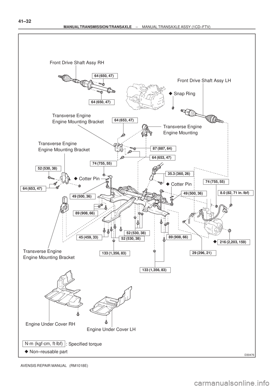
D30476
Front Drive Shaft Assy RH
Front Drive Shaft Assy LH
� Snap Ring
Transverse Engine
Engine Mounting Bracket
Transverse Engine
Engine Mounting
Transverse Engine
Engine Mounting Bracket
64 (653, 47)
� Cotter Pin
52 (530, 38)
� Cotter Pin
49 (500, 36)8.0 (82, 71 in.�lbf)
�216 (2,203, 159)
� Non±reusable part
N´m (kgf´cm, ft´lbf)
: Specified torque
Engine Under Cover RH
Engine Under Cover LH Transverse Engine
Engine Mounting Bracket
64 (650, 47)
64 (650, 47)
64 (653, 47)
87 (887, 64)
64 (653, 47)
49 (500, 36)
133 (1,356, 83)
45 (459, 33)
29 (296, 21)
52 (530, 38)
74 (755, 55)
74 (755, 55)
89 (908, 66)
133 (1,356, 83)
52 (530, 38)
89 (908, 66)
35.3 (360, 26)
41±32
± MANUAL TRANSMISSION/TRANSAXLEMANUAL TRANSAXLE ASSY (1CD±FTV)
AVENSIS REPAIR MANUAL (RM1018E)
Page 2781 of 5135
D30066
D30064
G24413
±
MANUAL TRANSMISSION/TRANSAXLE MANUAL TRANSAXLE ASSY (1AZ±FE/1AZ±FSE)
41±25
AVENSIS REPAIR MANUAL (RM1018E)
21. SEPARATE CONNECTOR
(a) Separate the back±up lamp switch connector.
22. SEPARATE CLUTCH RELEASE CYLINDER ASSY
(a) Remove the 3 bolts and separate the release cylinder.
23. SEPARATE TRANSMISSION CONTROL CABLE ASSY
(a) Remove the 2 clips, separate the 2 cables from the trans-
axle.
(b) Remove the 2 clips, separate the 2 cables from the brack- et.
24.REMOVE FRONT DRIVE SHAFT ASSY LH (See page 30±6) SST 09520±01010, 09520±24010 (09520±32040)
25.REMOVE FRONT DRIVE SHAFT ASSY RH (See page 30±6)
26. REMOVE HEIGHT CONTROL SENSOR SUB±ASSY FR RH (W/ DISCHARGE HEAD LAMP)\
(See page 65±28)
27.DISCONNECT STEERING GEAR OUTLET RETURN TUBE (See page 51±36) SST 09023±12700
28.DISCONNECT PRESSURE FEED TUBE ASSY (See page 51±36)
SST 09023±12700
Page 2784 of 5135

AVENSIS REPAIR MANUAL (RM1018E)
40. INSTALL MANUAL TRANSMISSION CASE PR")
D30076
D25747
AB
C
BA
D30077
D30067
A
A
A
A
B
41±28
±
MANUAL TRANSMISSION/TRANSAXLE MANUAL TRANSAXLE ASSY (1AZ±FE/1AZ±FSE)
AVENSIS REPAIR MANUAL (RM1018E)
40. INSTALL MANUAL TRANSMISSION CASE PROTECTOR
(a) Install the case protector with the 2 bolts.
Torque: 18 N �m (184 kgf �cm, 13 ft �lbf)
41. INSTALL MANUAL TRANSAXLE ASSY
(a) Align the input shaft with the clutch disc and install the transaxle to the engine.
(b) Install the 10 bolts. Torque:
Bolt A: 64 N �m (653 kgf �cm, 47 ft �lbf)
Bolt B: 46 N �m (469 kgf �cm, 34 ft �lbf)
Bolt C: 44 N �m (449 kgf �cm, 32 ft �lbf)
(c) Connect the wire harness clamp.
42. INSTALL TRANSVERSE ENGINE ENGINE MOUNTING BRACKET
(a) Install the engine mounting bracket LH to the transaxle with the 3 bolt.
Torque: 64 N �m (653 kgf �cm, 47 ft �lbf)
43. INSTALL TRANSVERSE ENGINE ENGINE MOUNTING INSULATOR
(a) Install the engine mounting insulator LH with the 5 bolts and nut.
Torque:
Bolt A: 52 N �m (530 kgf �cm, 38 ft �lbf)
Bolt B: 80 N �m (816 kgf �cm, 59 ft �lbf)
44.INSTALL FRONT SUSPENSION CROSSMEMBER SUB±ASSY (See page 26±26) SST 09670±00010
45.CONNECT PRESSURE FEED TUBE ASSY (See page 51±36)
SST 09023±12700
46.CONNECT STEERING GEAR OUTLET RETURN TUBE (See page 51±36) SST 09023±12700
47. INSTALL HEIGHT CONTROL SENSOR SUB±ASSY FR RH (W/ DISCHARGE HEAD LAMP)
(See page 65±28)
48.INSTALL FRONT DRIVE SHAFT ASSY LH (See page 30±6)
49.INSTALL FRONT DRIVE SHAFT ASSY RH (See page 30±6)
Page 2788 of 5135
D30473
Front Drive Shaft Assy RH
� Snap Ring
Transverse Engine
Engine Mounting Insulator
64 (653, 47)
87 (887, 64)
� Cotter Pin
64 (653, 47)
� Cotter Pin
Engine Under Cover RH
� Non±reusable part
N´m (kgf´cm, ft´lbf)
: Specified torque
64 (653, 47)
�216 (2,203, 159)45 (459, 33)
Engine Under Cover LH
35 (360, 26)
74 (755, 55)
52 (530, 38)
49 (500, 36)
133 (1,356, 83)
49 (500, 36)
89 (908, 66)
Transverse Engine
Engine Mounting Bracket
133 (1,356, 83)
52 (530, 38)89 (908, 66)
29 (296, 21)Transverse Engine
Engine Mounting Insulator
Transverse Engine
Engine Mounting Bracket
8.0 (82, 71 in.�lbf)
74 (755, 55)
Front Drive Shaft Assy LH
64 (650, 47)
64 (650, 47)
± MANUAL TRANSMISSION/TRANSAXLEMANUAL TRANSAXLE ASSY (1AZ±FE/1AZ±FSE)
41±23
AVENSIS REPAIR MANUAL (RM1018E)
Page 2790 of 5135
D30481
D30061
G24210
D11561
41±16
±
MANUAL TRANSMISSION/TRANSAXLE MANUAL TRANSAXLE ASSY (1ZZ±FE/3ZZ±FE)
AVENSIS REPAIR MANUAL (RM1018E)
20. DISCONNECT CONNECTOR
(a) Disconnect the back±up lamp switch connector.
21. SEPARATE CLUTCH RELEASE CYLINDER ASSY
(a) Remove the 5 bolts, separate the release cylinder assy with clutch piping from the transaxle.
22. SEPARATE CHARCOAL CANISTER ASSY 23. SEPARATE TRANSMISSION CONTROL CABLE ASSY
(a) Remove the 2 clips, disconnect the 2 cables from thetransaxle.
(b) Remove the 2 clips, disconnect the 2 cables from the con-
trol cable bracket.
24. REMOVE STARTER ASSY
(a) Remove the nut and disconnect the starter wire.
(b) Disconnect the connector.
(c) Remove the 2 bolts and starter assy.
25.REMOVE FRONT DRIVE SHAFT ASSY LH(See page 30±6) SST 09520±01010, 09520±24010 (09520±32040)
26.REMOVE FRONT DRIVE SHAFT ASSY RH (See page 30±6) SST 09520±01010, 09520±24010 (09520±32040)
Page 2793 of 5135

(c)
(b)(a)
G24210
±
MANUAL TRANSMISSION/TRANSAXLE MANUAL TRANSAXLE ASSY (1ZZ±FE/3ZZ±FE)
41±19
AVENSIS REPAIR MANUAL (RM1018E)
39. INSTALL TRANSVERSE ENGINE ENG")
D30484
D30483
A
A
A
A
B
D11561
(a)
(c)
(b)(a)
G24210
±
MANUAL TRANSMISSION/TRANSAXLE MANUAL TRANSAXLE ASSY (1ZZ±FE/3ZZ±FE)
41±19
AVENSIS REPAIR MANUAL (RM1018E)
39. INSTALL TRANSVERSE ENGINE ENGINE MOUNTING
BRACKET
(a) Install the engine mounting bracket LH to the transaxle
with the 3 bolts.
Torque: 64 N �m (653 kgf �cm, 47 ft �lbf)
40. INSTALL TRANSVERSE ENGINE ENGINE MOUNTING INSULATOR
(a) Install the engine mounting insulator LH with the 5 bolts and nut.
Torque:
Bolt A: 52 N �m (530 kgf �cm, 38 ft �lbf)
Bolt B: 80 N �m (816 kgf �cm, 59 ft �lbf)
41.INSTALL FRONT SUSPENSION CROSSMEMBER SUB±ASSY (See page 26±26) SST 09670±00010
42. INSTALL HEIGHT CONTROL SENSOR SUB±ASSY FR RH (W/ DISCHARGE HEAD LAMP) (See page 65±28)
43.INSTALL FRONT DRIVE SHAFT ASSY LH (See page 30±6)
44.INSTALL FRONT DRIVE SHAFT ASSY RH (See page 30±6)
45. INSTALL STARTER ASSY
(a) Install the starter assy and 2 bolts to the transaxle.Torque: 37 N �m (380 kgf �cm, 27 ft �lbf)
(b) Connect the starter connector.
(c) Install the wire and nut to the starter assy.
Torque: 13 N �m (130 kgf �cm, 9 ft �lbf)
46. CONNECT TRANSMISSION CONTROL CABLE ASSY
(a) Connect the 2 cable ends, install the 2 clips.
(b) Install the 2 clips to the control cable bracket.
Page 2797 of 5135
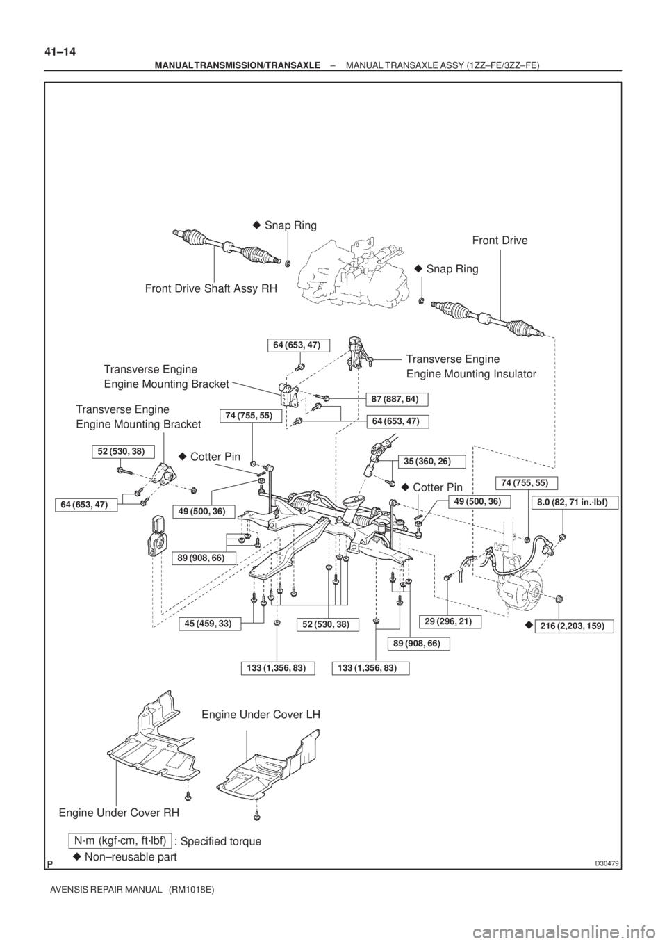
D30479
Front Drive Shaft Assy RH� Snap Ring
Front Drive
� Snap Ring
Transverse Engine
Engine Mounting BracketTransverse Engine
Engine Mounting Insulator
64 (653, 47)
87 (887, 64)Transverse Engine
Engine Mounting Bracket
� Cotter Pin
64 (653, 47)
52 (530, 38)
� Cotter Pin
Engine Under Cover RH
� Non±reusable part
N´m (kgf´cm, ft´lbf)
: Specified torque
64 (653, 47)
�216 (2,203, 159)45 (459, 33)
Engine Under Cover LH
35 (360, 26)
74 (755, 55)
52 (530, 38)
49 (500, 36)
133 (1,356, 83)
29 (296, 21)
49 (500, 36)
74 (755, 55)
89 (908, 66)
8.0 (82, 71 in.�lbf)
133 (1,356, 83)
89 (908, 66)
41±14
± MANUAL TRANSMISSION/TRANSAXLEMANUAL TRANSAXLE ASSY (1ZZ±FE/3ZZ±FE)
AVENSIS REPAIR MANUAL (RM1018E)
Page 2809 of 5135

33. REMOVE STEERING INTERMEDIATE SHAFT ASSY NO.2 (LHD")
F44793Matchmarks
F44794
Screw
Extractor
F44795
SST
F44796
F44797
50±14
±
STEERING COLUMN STEERING COLUMN ASSY
AVENSIS REPAIR MANUAL (RM1018E)
33. REMOVE STEERING INTERMEDIATE SHAFT ASSY NO.2 (LHD STEERING POSITION TYPE)
(a) Place matchmarks on the steering intermediate shaft
assy No. 2 and steering main shaft.
(b) Remove the bolt and steering intermediate shaft assy No. 2.
(c) W/VSC:
Remove the steering sensor (See page 32±65).
34. REMOVE STEERING COLUMN UPPER W/SWITCH BRACKET ASSY
(a) Using a centering punch, mark the center of the 2 ta- pered±head bolts.
(b) Using a 3 ± 4 mm (0.12 ± 0.16 in.)drill, drill into the 2 bolts.
(c) Using a screw extractor, remove the 2 bolts and steering column upper with switch bracket assy.
NOTICE:
Do not give the strong force to the motor part.
35. INSPECT STEERING COLUMN ASSY (ELECTRIC POWER STEERING)
(a) Using SST and a torque wrench, check the rotating torque.
SST 09616±00011
Rotating torque (1 turn for 2 sec.):
0.4 ± 1.1 N �m (4 ± 11 kgf �cm, 3.5 ± 9.5 in. �lbf)
36. REMOVE TRANSPONDER KEY AMPLIFIER
(a) Widen the claw hung on the upper bracket by approx. 1.0 mm (0.039 in.) using a screwdriver.
(b) Pull the transponder key amplifier toward the rear of the
vehicle with the claw open.
NOTICE:
Take care not to use excessive force to prevent the case
from being damaged.
37. REMOVE IGNITION SWITCH LOCK CYLINDER ASSY
(a) Place the ignition switch lock cylinder assy at the ACC position.
(b) Push down the stop pin with a screwdriver, and pull out the cylinder assy.

41±25
AVENSIS REPAIR MANUAL (RM1018E)
21. SEPARATE CONNECTOR
(a) Separate the back±up lamp switch con")


AVENSIS REPAIR MANUAL (RM1018E)
20. DISCONNECT CONNECTOR
(a) Disconnect the back±up lamp")