Page 3508 of 5135

(b) Using a screwdriver, pry out the s")
B10446
B10014
B10015
B10452ContinuityOhmmeter
B10453
Ohmmeter
No Continuity 19±10
± STARTING & CHARGINGGENERATOR ASSY
1AZ±FSE ENGINE REPAIR MANUAL (RM1019E)
(b) Using a screwdriver, pry out the stator sub±assy genera-
tor w/rectifire.
4. REMOVE BEARING SET GENERATOR
5. REMOVE PULLEY SET GENERATOR
(a) Clamp the swivel arm in a vise.
NOTICE:
Be careful not to damage the fan.
(b) Using an impact wrench or internal serration on rotor shaft
end together with a torque wrench,remove the nut and
spring washer, then detach the pulley.
6. REMOVE GENERATOR ROTOR ASSY
(a) Using a press, press out the generator rotor assy and
spacer ring.
7. INSPECT GENERATOR ROTOR ASSY
(a) Inspect the generator rotor assy for open circuit.
(1) Using an ohmmeter, check that there is continuity
between the slip rings.
Standard resistance: 2.27 to 2.53 � at 20�C (68�F)
If there is no continuity, replace the generator rotor assy.
(b) Inspect the generator rotor assy for ground.
(1) Using an ohmmeter, check that there is no continu-
ity between the slip ring and the generator rotor
assy.
If there is continuity, replace the generator rotor assy.
Page 3516 of 5135
C80539
SST
C68005
���
C80431
C80541
D30552
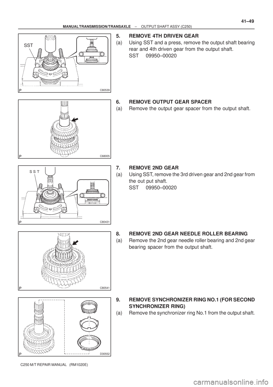
± MANUAL TRANSMISSION/TRANSAXLEOUTPUT SHAFT ASSY (C250)
41±49
C250 M/T REPAIR MANUAL (RM1020E)
5. REMOVE 4TH DRIVEN GEAR
(a) Using SST and a press, remove the output shaft bearing
rear and 4th driven gear from the output shaft.
SST 09950±00020
6. REMOVE OUTPUT GEAR SPACER
(a) Remove the output gear spacer from the output shaft.
7. REMOVE 2ND GEAR
(a) Using SST, remove the 3rd driven gear and 2nd gear from
the out put shaft.
SST 09950±00020
8. REMOVE 2ND GEAR NEEDLE ROLLER BEARING
(a) Remove the 2nd gear needle roller bearing and 2nd gear
bearing spacer from the output shaft.
9. REMOVE SYNCHRONIZER RING NO.1 (FOR SECOND
SYNCHRONIZER RING)
(a) Remove the synchronizer ring No.1 from the output shaft.
Page 3517 of 5135
C80543
C80544
SST
C68516
C68012
C68013
41±50
± MANUAL TRANSMISSION/TRANSAXLEOUTPUT SHAFT ASSY (C250)
C250 M/T REPAIR MANUAL (RM1020E)
10. REMOVE 1ST GEAR
(a) Using 2 screwdrivers and a hammer, remove the clutch
hub No.1 shaft snap ring from the output shaft.
HINT:
Using a shop rug to prevent the shaft snap ring from being
scatted.
(b) Using SST and a press, remove the clutch hub No.1 assy
and 1st gear from the output shaft.
SST 09950±00020
11. REMOVE SYNCHRONIZER RING NO.1 (FOR FIRST
SYNCHRONIZER RING)
(a) Remove the synchronizer ring No.1 from the 1st gear.
12. REMOVE 1ST GEAR NEEDLE ROLLER BEARING
(a) Remove the 1st gear needle roller bearing from the output
shaft.
13. REMOVE 1ST GEAR THRUST WASHER
(a) Remove the 1st gear thrust washer from the output shaft.
Page 3523 of 5135
C68248
C80548
SST
C68005
C82013
SST
C82014
SST
41±56
± MANUAL TRANSMISSION/TRANSAXLEOUTPUT SHAFT ASSY (C250)
C250 M/T REPAIR MANUAL (RM1020E)
33. INSTALL 2ND GEAR
(a) Coat the 2nd gear with gear oil, install it to the output
shaft.
34. INSTALL 3RD DRIVEN GEAR
(a) Using SST and a press, install the 3rd driven gear to the
output shaft.
SST 09950±00020
35. INSTALL OUTPUT GEAR SPACER
(a) Install the output gear spacer to the output shaft.
36. INSTALL 4TH DRIVEN GEAR
(a) Using SST and a press, 4th driven gear to the output
shaft.
SST 09612±22011
37. INSTALL OUTPUT SHAFT REAR BEARING
(a) Using SST and a press, install the output shaft rear bear-
ing to the output shaft.
SST 09612±22011
Page 3525 of 5135
410DG±01
D30520
Apply MP grease
1st Gear Thrust Washer Pin Or Ball
Output Shaft
1st Gear Needle Roller Bearing
1st Gear Thrust Washer
1st Gear
Reverse Gear
Synchronizer Ring No.1 (For 1st)
Synchromesh Shifting Key No.1
Synchromesh Shifting Key Spring No.1
Synchronizer Ring No.1 (For 2nd)
Clutch Hub No.1
Shaft Snap Ring
Transmission Clutch Hub No.1
2nd Gear Bearing Spacer
2nd Gear Needle Roller Bearing
2nd Gear
3rd Driven Gear
Output Gear Spacer
4th Driver Gear
Output Shaft Rear Bearing
x3
x3
± MANUAL TRANSMISSION/TRANSAXLEOUTPUT SHAFT ASSY (C250)
41±47
C250 M/T REPAIR MANUAL (RM1020E)
OUTPUT SHAFT ASSY (C250)
COMPONENTS
Page 3527 of 5135
C80559
Q04983
SST
C80560
C80561
C67821
± MANUAL TRANSMISSION/TRANSAXLEINPUT SHAFT ASSY (C250)
41±39
C250 M/T REPAIR MANUAL (RM1020E)
5. REMOVE 4TH GEAR
(a) Using 2 screwdrivers and a hammer, remove the input
shaft rear bearing shaft snap ring from input shaft.
(b) Using SST and a press, remove the input shaft radial ball
bearing rear and 4th gear from input shaft.
NOTICE:
Do not tighten SST excessively.
SST 09950±00020
6. REMOVE 4TH GEAR NEEDLE ROLLER BEARING
(a) Remove the 4th gear needle roller bearing and 4th gear
bearing spacer from input shaft.
7. REMOVE SYNCHRONIZER RING NO.2 (FOR FOURTH
SYNCHRONIZER RING)
(a) Remove synchronizer ring No.2 from transmission clutch
hub No.2.
8. REMOVE 3RD GEAR
(a) Using 2 screwdrivers and a hammer, remove the clutch
hub No.2 setting shaft snap ring from the input shaft.
NOTICE:
Using a shop rug to prevent the snap ring from being scat-
tered.
Page 3541 of 5135

41±9
C250 M/T REPAIR MANUAL (RM1020E)
21. REMOVE TRANSMISSION CLUTCH HUB NO.3
(a) Using 2 scr")
D30536
C80347
SST
D07737
D30537
D30538
SST
± MANUAL TRANSMISSION/TRANSAXLEMANUAL TRANSAXLE ASSY (C250)
41±9
C250 M/T REPAIR MANUAL (RM1020E)
21. REMOVE TRANSMISSION CLUTCH HUB NO.3
(a) Using 2 screwdrivers and a hammer, tap out the snap
ring.
HINT:
Using a shop rug to prevent the snap ring from being scattered.
(b) Using SST, remove the transmission clutch hub No.3, 5th
gear and synchronizer ring from the input shaft.
SST 09950±40011 (09951±04020, 09952±04010,
09953±04030, 09954±04010, 09955±04071,
09957±04010), 09950±60010 (09951±00200)
(c) Remove the 3 synchromesh shifting keys and 2 synchro-
mesh shifting key springs from the transmission clutch
hub No.3.
22. REMOVE 5TH GEAR NEEDLE ROLLER BEARING
(a) Remove the 5th gear needle roller bearing and 5th gear
bearing spacer from the input shaft.
23. REMOVE 5TH DRIVEN GEAR
(a) Using SST, remove the 5th driven gear from the output
shaft.
SST 09950±30012 (09951±03010, 09953±03010,
09954±03010, 09955±03011, 09957±04010),
09950±60010 (09951±00190)
Page 3542 of 5135
D30539
C80351
C80352
D30540
C80353
41±10
± MANUAL TRANSMISSION/TRANSAXLEMANUAL TRANSAXLE ASSY (C250)
C250 M/T REPAIR MANUAL (RM1020E)
24. REMOVE BEARING RETAINER REAR (MTM)
(a) Remove the 5 bolts and bearing retainer rear from the
manual transmission case.
25. REMOVE OUTPUT SHAFT REAR BEARING HOLE
SNAP RING
(a) Using a snap ring expander, remove the output shaft rear
bearing hole snap ring from the output shaft.
26. REMOVE INPUT SHAFT REAR BEARING HOLE SNAP
RING
(a) Using a snap ring expander, remove the input shaft rear
bearing hole snap ring from the input shaft.
27. REMOVE REVERSE IDLER GEAR SHAFT BOLT
(a) Remove the reverse idler gear shaft bolt and reverse idler
gear shaft gasket from the manual transmission case.
28. REMOVE SHIFT FORK SHAFT SHAFT SNAP RING
(a) Using 2 screwdrivers and a hammer, tap out the snap
ring.
HINT:
Using a shop rug to the shifting key spring from being scattered.

C250 M/T REPAIR MANUAL (RM1020E)
10. REMOVE 1ST GEAR
(a) Using 2 screwdrivers and a hammer, rem")

C250 M/T REPAIR MANUAL (RM1020E)
33. INSTALL 2ND GEAR
(a) Coat the 2nd gear with gear o")

Synchromes")

41±39
C250 M/T REPAIR MANUAL (RM1020E)
5. REMOVE 4TH GEAR
(a) Using 2 screwdrivers and a hammer, remov")

C250 M/T REPAIR MANUAL (RM1020E)
24. REMOVE BEARING RETAINER REAR (MTM)
(a) Remove the 5 bolts")