Page 3545 of 5135
C80361
C80362
C80363
C80364
C80365
± MANUAL TRANSMISSION/TRANSAXLEMANUAL TRANSAXLE ASSY (C250)
41±13
C250 M/T REPAIR MANUAL (RM1020E)
34. REMOVE GEAR SHIFT FORK SHAFT NO.2
(a) Remove the 2 bolts from the gear shift fork No.2 and gear
shift head No.1.
(b) Remove the gear shift fork shaft No.2 and gear shift head
No.1 from the front transaxle case.
35. REMOVE GEAR SHIFT FORK SHAFT NO.1
(a) Using 2 screwdrivers and a hammer, tap out the snap
rings.
HINT:
Using a shop rug to prevent the snap ring from being scattered.
(b) Remove the shift fork set bolt and gear shift fork shaft
No.1 from the gear shift fork No.1.
(c) Remove the shift fork No.1.
Page 3546 of 5135
C80366
C80367
C80368
C80369
C80586
41±14
± MANUAL TRANSMISSION/TRANSAXLEMANUAL TRANSAXLE ASSY (C250)
C250 M/T REPAIR MANUAL (RM1020E)
36. REMOVE GEAR SHIFT FORK SHAFT NO.3
(a) Using 2 screwdrivers and a hammer, tap out the snap ring
from the gear shift fork shaft No.3.
HINT:
Using a shop rug to prevent the snap ring from being scattered.
(b) Remove the shift fork shaft No.3, reverse shift fork and
gear shift fork No.2 from the manual transaxle case.
(c) Using a magnetic finger, remove the 2 reverse shift fork
balls from the reverse shift fork.
(d) Using 2 screwdrivers and a hammer, tap out the snap ring
from the shift fork shaft No.3.
HINT:
Using a shop rug to prevent the snap ring from being scattered.
(e) Remove the reverse shift fork from the gear shift fork shaft
No.3.
37. REMOVE INPUT SHAFT ASSY
(a) Remove the input shaft assy and output shaft assy from
the front transaxle case.
Page 3550 of 5135

C250 M/T REPAIR MANUAL (RM1020E)
51. REMOVE FR DIFFERENTIAL CASE REAR TAPERED
R")
C81788
SST
C82144
SST
C81787
SST
D30571
SST
C67848
41±18
± MANUAL TRANSMISSION/TRANSAXLEMANUAL TRANSAXLE ASSY (C250)
C250 M/T REPAIR MANUAL (RM1020E)
51. REMOVE FR DIFFERENTIAL CASE REAR TAPERED
ROLLER BEARING
(a) Using SST, remove the front differential case rear tapered
roller bearing (outer race) and shim from the transmission
case.
SST 09612±65014 (09612±01040, 09612±01050)
(b) Using SST and hammer, remove the front differential
case rear tapered roller bearing (inner race) from the front
differential case.
SST 09950±40011 (09951±04010, 09952±04010,
09953±04020, 09954±04010, 09955±04061,
09957±04010, 09958±04011), 09950±60010
(09951±00360)
NOTICE:
Be careful not to damage bearing.
52. REMOVE TRANSMISSION CASE OIL SEAL
(a) Using SST and hammer, drive out the transmission case
oil seal from the manual transmission case.
SST 09950±60010 (09951±00600), 09950±70010
(09951±07100)
53. REMOVE SHIFT & SELECT LEVER SHAFT NEEDLE
ROLLER BEARING
(a) Using SST, remove the shift & select lever shaft needle
roller bearing.
SST 09319±60020
54. INSPECT SYNCHRONIZER RING NO.3
(a) Check for wear or damage.
(b) Check the braking effect of the synchronizer ring. Turn the
synchronizer ring in one direction while pushing it to the
gear cone, check that the ring locks.
If the braking effect is insufficient, apply a small amount of the
fine lapping compound between the synchronizer ring and gear
cone. Lightly rub the synchronizer ring and gear cone together.
Page 3553 of 5135

41±21
C250 M/T REPAIR MANUAL (RM1020E)
60. INSTALL FRONT TRANSAXLE CASE OIL SEAL")
C81790
SST
C81791
SST
D30572
SST
C82146
SST
C80379
SST
± MANUAL TRANSMISSION/TRANSAXLEMANUAL TRANSAXLE ASSY (C250)
41±21
C250 M/T REPAIR MANUAL (RM1020E)
60. INSTALL FRONT TRANSAXLE CASE OIL SEAL
(a) Using SST and a hammer, install a new front transaxle
case oil seal to the front transaxle case.
SST 09950±60010 (09951±00370), 09950±70010
(09951±07150)
Drive in depth: 15.6 ± 16.0 mm (0.6141 ± 0.6299 in.)
(b) Coat the lip of the front transaxle case oil seal with MP
grease.
61. INSTALL INPUT SHAFT FRONT BEARING
(a) Coat the new input shaft front bearing with MP grease, us-
ing SST and a press, install it to the front transaxle case.
SST 09950±60010 (09951±00420), 09950±70010
(09951±07150)
Drive in depth: 0 ± 0.3 mm (0 ± 0.0118 in.)
62. INSTALL SHIFT & SELECT LEVER SHAFT NEEDLE
ROLLER BEARING
(a) Using SST, install the shift & select lever shaft needle roll-
er bearing.
SST 09950±60010 (09951±00220), 09950±70010
(09951±07100)
Drive in depth: 0 ± 0.5 mm (0 ± 00020 in.)
63. INSTALL FR DIFFERENTIAL CASE FRONT TAPERED
ROLLER BEARING
(a) Using SST and a press, install the front differential case
front tapered roller bearing (inner race) to the front differ-
ential case.
SST 09350±32014 (09351±32120), 09950±60010
(09951±00530)
(b) Using SST and a press, install the front differential case
front tapered roller bearing (outer race) with shim to the
front transaxle case.
SST 09950±60020 (09951±00680), 09950±70010
(09951±07150)
Page 3562 of 5135
D30539
D30568
SST
D30537
C80396
C80397
Key Position 41±30
± MANUAL TRANSMISSION/TRANSAXLEMANUAL TRANSAXLE ASSY (C250)
C250 M/T REPAIR MANUAL (RM1020E)
88. INSTALL BEARING RETAINER REAR (MTM)
(a) Coat the 5 bolts with sealant, install them and bearing re-
tainer rear to the manual transmission case.
Torque: 27 N�m (280 kgf�cm, 20 ft�lbf)
89. INSTALL 5TH DRIVEN GEAR
(a) Using SST, install the 5th driven gear to the output shaft.
SST 09950±30012 (09951±03010, 09953±03010,
09954±03010, 09955±03011, 09956±03020)
90. INSTALL 5TH GEAR NEEDLE ROLLER BEARING
(a) Coat the 5th gear needle roller bearing and spacer with
gear oil, install them to the input shaft.
91. INSTALL 5TH GEAR
(a) Coat the 5th gear with gear oil, install it to the input shaft.
92. INSTALL SYNCHRONIZER RING NO.3
(a) Coat the synchronizer ring No.3 with gear oil, install it to
the 5th gear.
Page 3574 of 5135
410DK±01
������
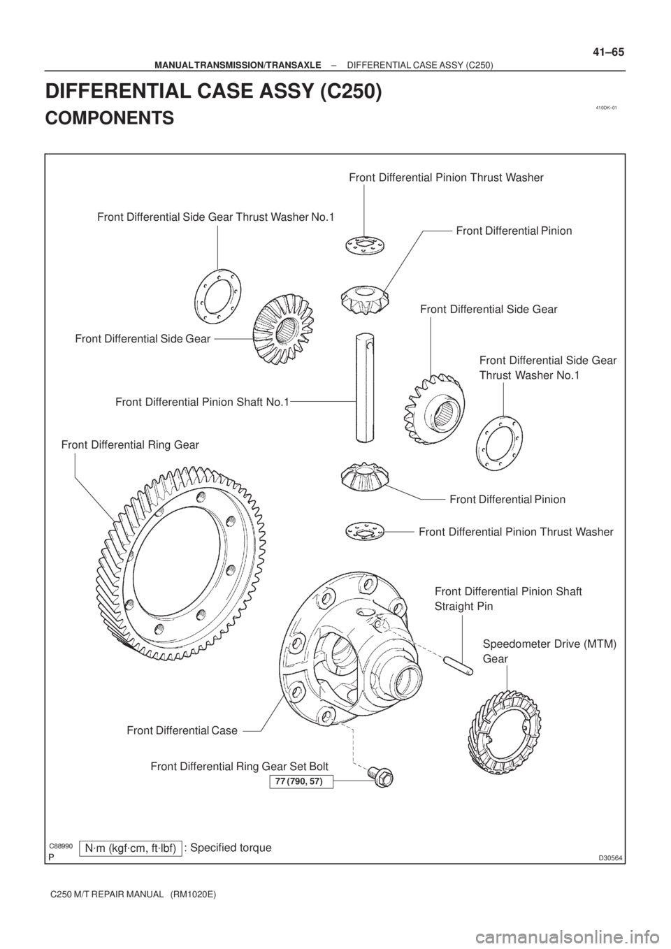
D30564
Front Differential Pinion Front Differential Pinion Thrust Washer
N�m (kgf�cm, ft�lbf): Specified torque
77 (790, 57)
Front Differential Ring Gear Set Bolt Front Differential CaseFront Differential Side Gear
Front Differential Side Gear
Thrust Washer No.1
Front Differential Pinion
Front Differential Pinion Thrust Washer
Front Differential Pinion Shaft
Straight Pin Front Differential Side GearFront Differential Side Gear Thrust Washer No.1
Speedometer Drive (MTM)
Gear Front Differential Ring GearFront Differential Pinion Shaft No.1
± MANUAL TRANSMISSION/TRANSAXLEDIFFERENTIAL CASE ASSY (C250)
41±65
C250 M/T REPAIR MANUAL (RM1020E)
DIFFERENTIAL CASE ASSY (C250)
COMPONENTS
Page 3576 of 5135

41±61
C250 M/T REPAIR MANUAL (RM1020E)
5. REMOVE SELECTING BELLCRANK NO.2 BUSH
(a) Rem")
C80764
Bush
C80572
D30553
D30554
D30555
± MANUAL TRANSMISSION/TRANSAXLESHIFT & SELECT LEVER SHAFT ASSY (C250)
41±61
C250 M/T REPAIR MANUAL (RM1020E)
5. REMOVE SELECTING BELLCRANK NO.2 BUSH
(a) Remove the 2 selecting bellcrank No.2 bushes from the
selecting bellcrank.
6. REMOVE SELECT SPRING SEAT NO.2
(a) Using a screwdriver, remove the select spring seat No.2
E±ring, select spring seat No.2 and select return spring
No.2 from the shift & select lever shaft.
7. REMOVE SHIFT LEVER INNER NO.2
(a) Using a pin punch (�5mm) and hammer, remove the shift
inner lever slotted pin and shift lever inner No.2 from the
shift & select lever shaft.
HINT:
Make sure of the orientation of the shift lever inner No.2.
8. REMOVE SHIFT LEVER INNER NO.1
(a) Using a pin punch (�5mm) and hammer, remove the shift
inner lever slotted pin, shift lever inner No.1 and shift inter
lock plate from the shift & select lever shaft.
HINT:
Make sure of the orientation of the shift lever inner No.1.
9. REMOVE SELECT INNER LEVER
(a) Using a pin punch (�5mm) and hammer, remove the se-
lect inner lever slotted pin, select inner lever select return
spring No.1 and select return spring No.1 seat from shift
& select lever shaft.
HINT:
Make sure of the orientation of the select inner lever.
Page 3577 of 5135

C250 M/T REPAIR MANUAL (RM1020E)
10. REMOVE SELECT SPRING NO.1 SEAT SHAFT SNAP
RING
(a)")
D30556
C80778
C94255
SST
D30557
41±62
± MANUAL TRANSMISSION/TRANSAXLESHIFT & SELECT LEVER SHAFT ASSY (C250)
C250 M/T REPAIR MANUAL (RM1020E)
10. REMOVE SELECT SPRING NO.1 SEAT SHAFT SNAP
RING
(a) Using 2 screwdrivers and a hammer, remove the select
spring No.1 seat shaft snap ring.
NOTICE:
Do not damage the shaft.
11. REMOVE SHIFT & SELECT LEVER SHAFT DUST BOOT
(a) Remove the shift & select lever shaft dust boot from the shift & select lever shaft.
12. REMOVE CONTROL SHAFT COVER OIL SEAL
(a) Using a screwdriver remove the control shaft cover oil
seal from the control shaft cover.
13. INSTALL CONTROL SHAFT COVER OIL SEAL
(a) Using SST and a hammer, install the new control shaft
cover oil seal to the control shaft cover.
SST 09950±60010 (09951±00220), 09950±70010
(09951±07100)
Drive in depth:
0.2 ± 1.2 mm (0.079 ± 0.0472 in.)
(b) Coat the control shaft cover oil seal with MP grease.
14. INSTALL SHIFT & SELECT LEVER SHAFT DUST
BOOT
(a) Coat the shift & select lever shaft dust boot with MP
grease.
(b) Install the shift & select lever shaft dust boot to the shift
& select lever shaft.
HINT:
Install the boot with the projection up and the hole side down.

41±13
C250 M/T REPAIR MANUAL (RM1020E)
34. REMOVE GEAR SHIFT FORK SHAFT NO.2
(a) Remove the 2 bolts f")

C250 M/T REPAIR MANUAL (RM1020E)
36. REMOVE GEAR SHIFT FORK SHAFT NO.3
(a) Using 2 screwdrivers")

C250 M/T REPAIR MANUAL (RM1020E)
88. INSTALL BEARING RETAINER REAR (MTM)
(a) C")