Page 3787 of 5135
A62817SST
A62202
Cut Position
A01153
A01456
14±10
± ENGINE MECHANICALPARTIAL ENGINE ASSY (1ZZ±FE/3ZZ±FE)
1ZZ±FE,3ZZ±FE ENGINE REPAIR MANUAL
(RM923E)
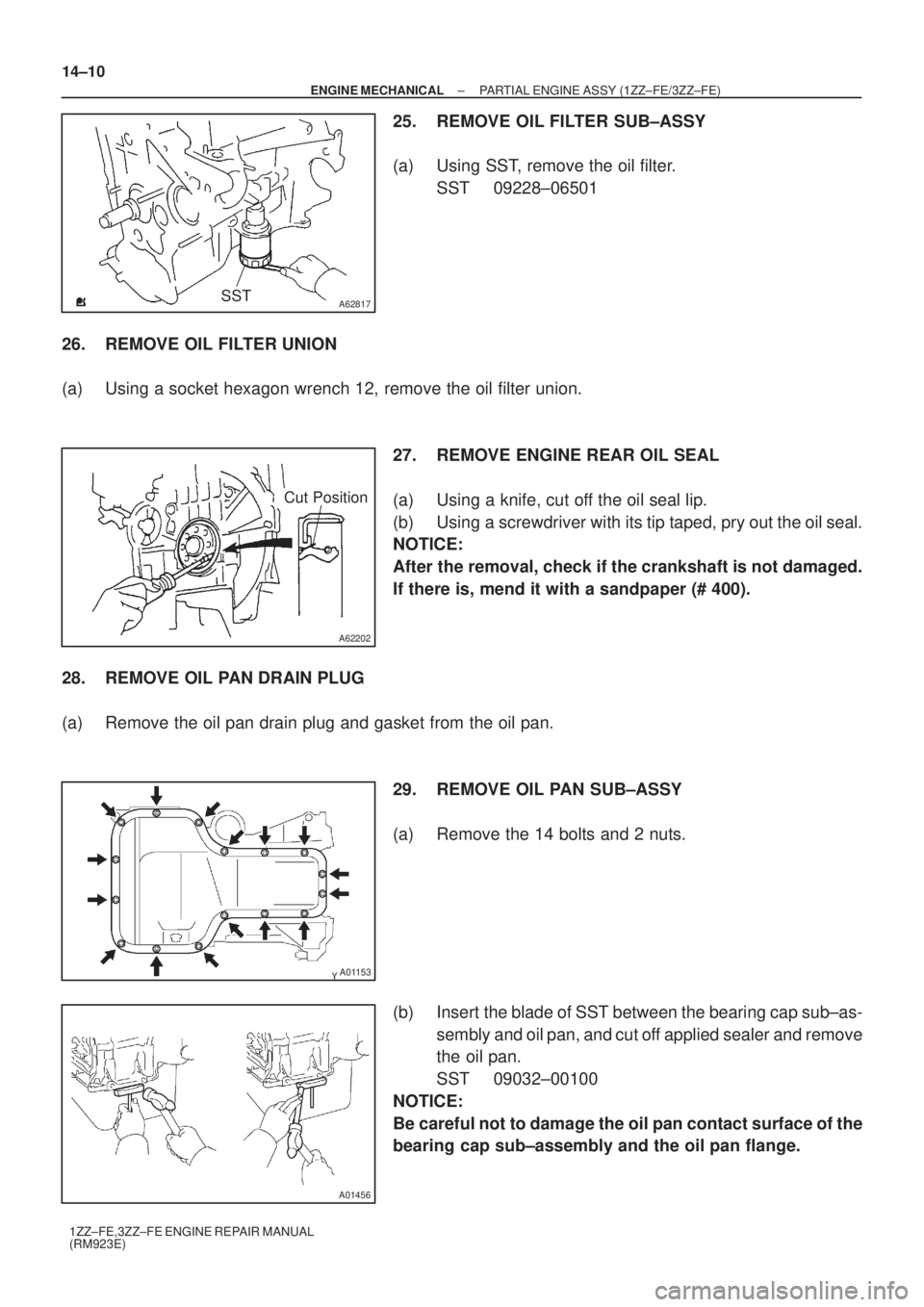
25. REMOVE OIL FILTER SUB±ASSY
(a) Using SST, remove the oil filter.
SST 09228±06501
26. REMOVE OIL FILTER UNION
(a) Using a socket hexagon wrench 12, remove the oil filter union.
27. REMOVE ENGINE REAR OIL SEAL
(a) Using a knife, cut off the oil seal lip.
(b) Using a screwdriver with its tip taped, pry out the oil seal.
NOTICE:
After the removal, check if the crankshaft is not damaged.
If there is, mend it with a sandpaper (# 400).
28. REMOVE OIL PAN DRAIN PLUG
(a) Remove the oil pan drain plug and gasket from the oil pan.
29. REMOVE OIL PAN SUB±ASSY
(a) Remove the 14 bolts and 2 nuts.
(b) Insert the blade of SST between the bearing cap sub±as-
sembly and oil pan, and cut off applied sealer and remove
the oil pan.
SST 09032±00100
NOTICE:
Be careful not to damage the oil pan contact surface of the
bearing cap sub±assembly and the oil pan flange.
Page 3792 of 5135
A30890
A62826
Lot No.
A62816
84 2 59
7 3 1 6 10
A62823
Paint Mark
90�
Front
A62815
Mesh
± ENGINE MECHANICALPARTIAL ENGINE ASSY (1ZZ±FE/3ZZ±FE)
14±15
1ZZ±FE,3ZZ±FE ENGINE REPAIR MANUAL
(RM923E)
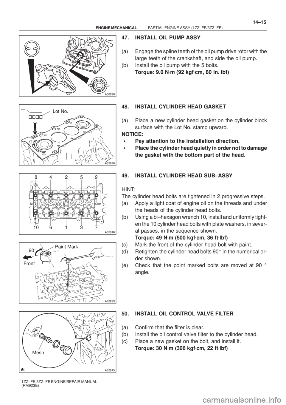
47. INSTALL OIL PUMP ASSY
(a) Engage the spline teeth of the oil pump drive rotor with the
large teeth of the crankshaft, and side the oil pump.
(b) Install the oil pump with the 5 bolts.
Torque: 9.0 N�m (92 kgf�cm, 80 in.�lbf)
48. INSTALL CYLINDER HEAD GASKET
(a) Place a new cylinder head gasket on the cylinder block
surface with the Lot No. stamp upward.
NOTICE:
�Pay attention to the installation direction.
�Place the cylinder head quietly in order not to damage
the gasket with the bottom part of the head.
49. INSTALL CYLINDER HEAD SUB±ASSY
HINT:
The cylinder head bolts are tightened in 2 progressive steps.
(a) Apply a light coat of engine oil on the threads and under
the heads of the cylinder head bolts.
(b) Using a bi±hexagon wrench 10, install and uniformly tight-
en the 10 cylinder head bolts with plate washers, in sever-
al passes, in the sequence shown.
Torque: 49 N�m (500 kgf�cm, 36 ft�lbf)
(c) Mark the front of the cylinder head bolt with paint.
(d) Retighten the cylinder head bolts 90� in the numerical or-
der shown.
(e) Check that the point marked bolts are moved at 90 �
angle.
50. INSTALL OIL CONTROL VALVE FILTER
(a) Confirm that the filter is clear.
(b) Install the oil control valve filter to the cylinder head.
(c) Place a new gasket on the bolt, and install it.
Torque: 30 N�m (306 kgf�cm, 22 ft�lbf)
Page 3797 of 5135
A62837SST
A62180
Disconnect
Hook
Pin Turn
A62181
Plunger
Turn
Push
A10085
A62179
A
ABB B
B 14±20
± ENGINE MECHANICALPARTIAL ENGINE ASSY (1ZZ±FE/3ZZ±FE)
1ZZ±FE,3ZZ±FE ENGINE REPAIR MANUAL
(RM923E)
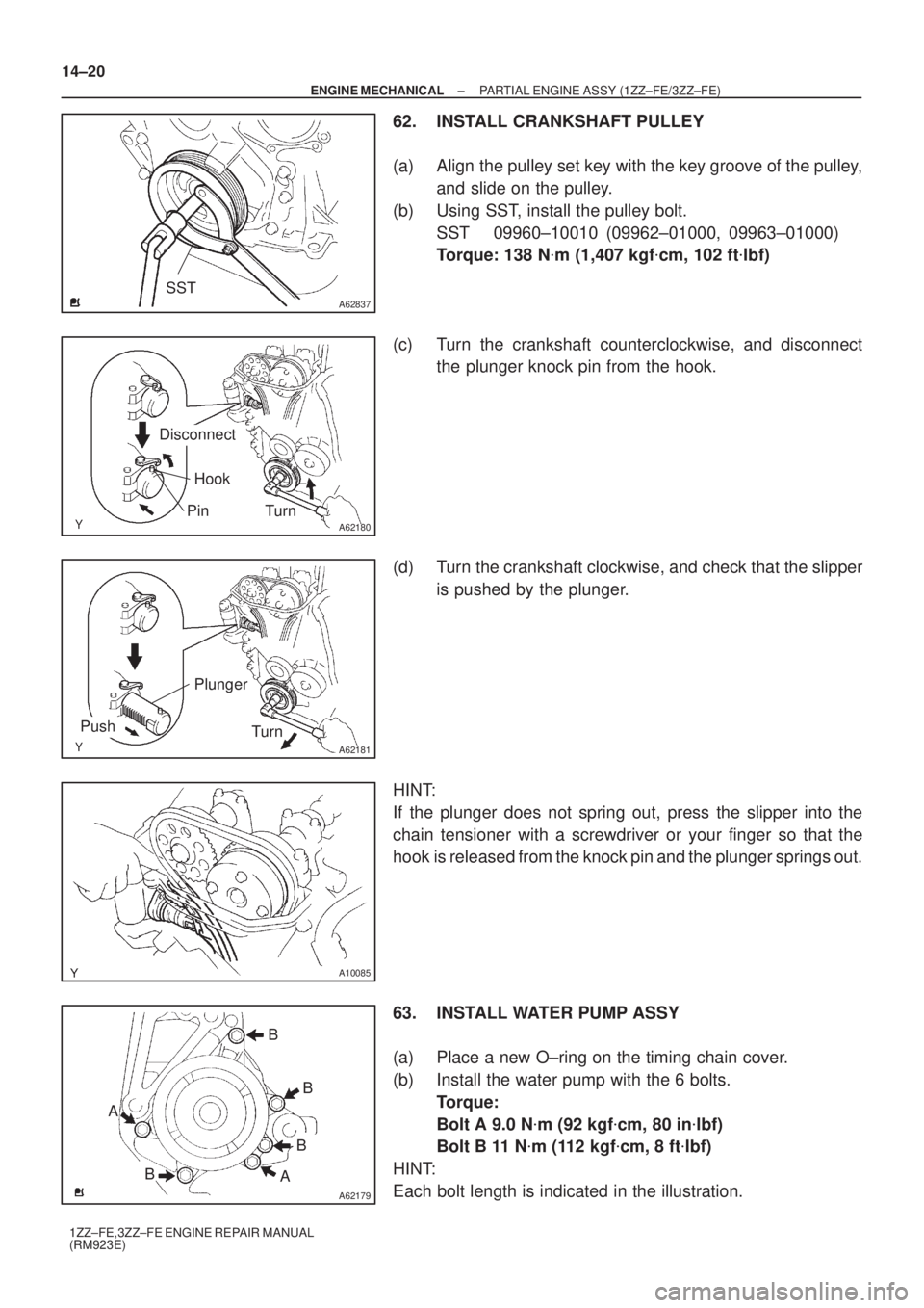
62. INSTALL CRANKSHAFT PULLEY
(a) Align the pulley set key with the key groove of the pulley,
and slide on the pulley.
(b) Using SST, install the pulley bolt.
SST 09960±10010 (09962±01000, 09963±01000)
Torque: 138 N�m (1,407 kgf�cm, 102 ft�lbf)
(c) Turn the crankshaft counterclockwise, and disconnect
the plunger knock pin from the hook.
(d) Turn the crankshaft clockwise, and check that the slipper
is pushed by the plunger.
HINT:
If the plunger does not spring out, press the slipper into the
chain tensioner with a screwdriver or your finger so that the
hook is released from the knock pin and the plunger springs out.
63. INSTALL WATER PUMP ASSY
(a) Place a new O±ring on the timing chain cover.
(b) Install the water pump with the 6 bolts.
Torque:
Bolt A 9.0 N�m (92 kgf�cm, 80 in�lbf)
Bolt B 11 N�m (112 kgf�cm, 8 ft�lbf)
HINT:
Each bolt length is indicated in the illustration.
Page 3803 of 5135
A62181
Plunger
Turn
Push
A10085
A62182
Seal Packing
14±26
± ENGINE MECHANICALPARTIAL ENGINE ASSY (1ZZ±FE/3ZZ±FE)
1ZZ±FE,3ZZ±FE ENGINE REPAIR MANUAL
(RM923E)
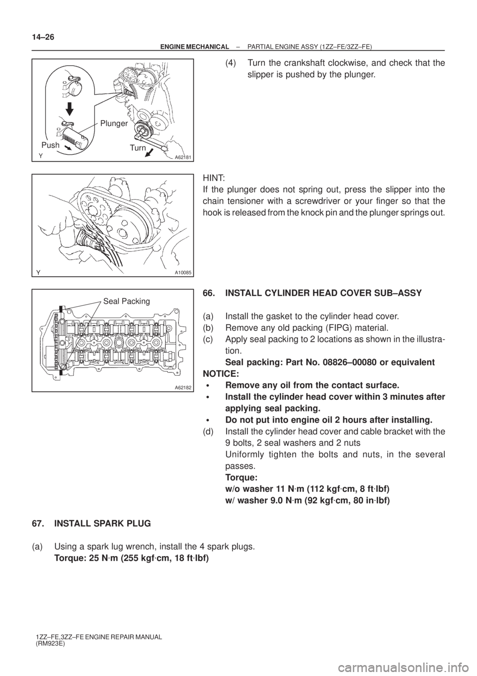
(4) Turn the crankshaft clockwise, and check that the
slipper is pushed by the plunger.
HINT:
If the plunger does not spring out, press the slipper into the
chain tensioner with a screwdriver or your finger so that the
hook is released from the knock pin and the plunger springs out.
66. INSTALL CYLINDER HEAD COVER SUB±ASSY
(a) Install the gasket to the cylinder head cover.
(b) Remove any old packing (FIPG) material.
(c) Apply seal packing to 2 locations as shown in the illustra-
tion.
Seal packing: Part No. 08826±00080 or equivalent
NOTICE:
�Remove any oil from the contact surface.
�Install the cylinder head cover within 3 minutes after
applying seal packing.
�Do not put into engine oil 2 hours after installing.
(d) Install the cylinder head cover and cable bracket with the
9 bolts, 2 seal washers and 2 nuts
Uniformly tighten the bolts and nuts, in the several
passes.
Torque:
w/o washer 11 N�m (112 kgf�cm, 8 ft�lbf)
w/ washer 9.0 N�m (92 kgf�cm, 80 in�lbf)
67. INSTALL SPARK PLUG
(a) Using a spark lug wrench, install the 4 spark plugs.
Torque: 25 N�m (255 kgf�cm, 18 ft�lbf)
Page 3811 of 5135
A09496
A09497
A08026
A09503
± ENGINE MECHANICALCYLINDER BLOCK (1CD±FTV)
14±43
1CD±FTV ENGINE REPAIR MANUAL (RM927E)
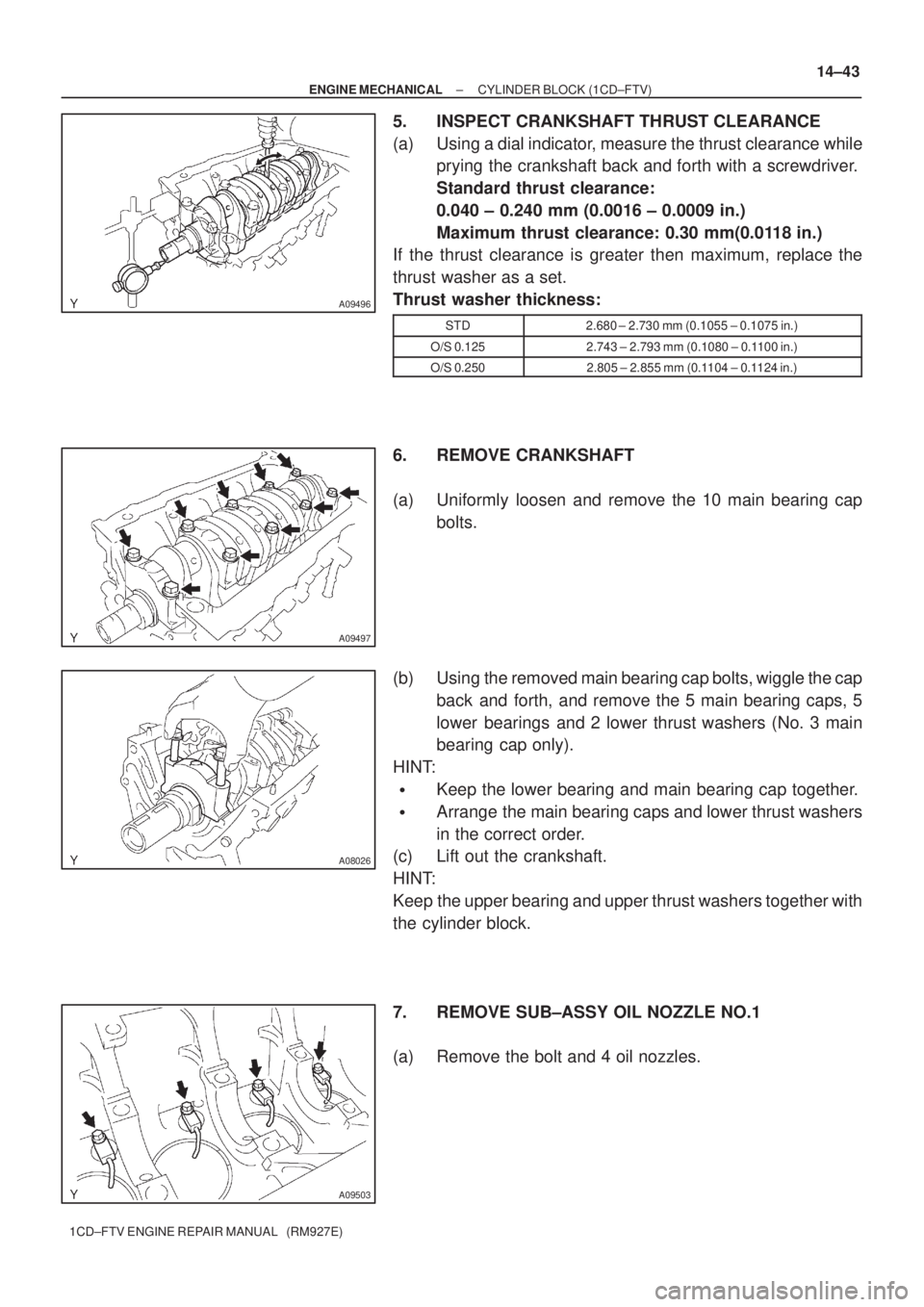
5. INSPECT CRANKSHAFT THRUST CLEARANCE
(a) Using a dial indicator, measure the thrust clearance while
prying the crankshaft back and forth with a screwdriver.
Standard thrust clearance:
0.040 ± 0.240 mm (0.0016 ± 0.0009 in.)
Maximum thrust clearance: 0.30 mm(0.0118 in.)
If the thrust clearance is greater then maximum, replace the
thrust washer as a set.
Thrust washer thickness:
STD2.680 ± 2.730 mm (0.1055 ± 0.1075 in.)
O/S 0.1252.743 ± 2.793 mm (0.1080 ± 0.1100 in.)
O/S 0.2502.805 ± 2.855 mm (0.1104 ± 0.1124 in.)
6. REMOVE CRANKSHAFT
(a) Uniformly loosen and remove the 10 main bearing cap
bolts.
(b) Using the removed main bearing cap bolts, wiggle the cap
back and forth, and remove the 5 main bearing caps, 5
lower bearings and 2 lower thrust washers (No. 3 main
bearing cap only).
HINT:
�Keep the lower bearing and main bearing cap together.
�Arrange the main bearing caps and lower thrust washers
in the correct order.
(c) Lift out the crankshaft.
HINT:
Keep the upper bearing and upper thrust washers together with
the cylinder block.
7. REMOVE SUB±ASSY OIL NOZZLE NO.1
(a) Remove the bolt and 4 oil nozzles.
Page 3847 of 5135
A57097
A57098
A09650
1 3
24
576
8
9
10 11
12
13 14
15
A09624
± ENGINE MECHANICALPARTIAL ENGINE ASSY (1CD±FTV)
14±5
1CD±FTV ENGINE REPAIR MANUAL (RM927E)
11. REMOVE CAMSHAFT OIL SEAL RETAINER
(a) Remove the 4 bolts.
(b) Using a screwdriver, remove the oil seal retainer by prying
the portions between the oil seal retainer and camshaft
bearing cap.
12. REMOVE WATER PUMP ASSY
(a) Remove the 7 bolts, water pump and gasket.
13. REMOVE CAMSHAFT SUB±ASSY, NO.2
(a) Uniformly loosen and remove the 15 bearing cap bolts in
several passes in the sequence shown.
(b) Remove the 5 bearing caps.
(c) Remove the camshaft No. 2.
14. REMOVE CAMSHAFT SUB±ASSY, NO.1
(a) Remove the camshaft from the cylinder head.
(b) Remove the camshaft carrier from the cylinder head.
Page 3850 of 5135
A09619
SST
A09620
B07976
A56700
SST
14±8
± ENGINE MECHANICALPARTIAL ENGINE ASSY (1CD±FTV)
1CD±FTV ENGINE REPAIR MANUAL (RM927E)
22. REMOVE CYLINDER BLOCK WATER DRAIN COCK SUB±ASSY
23. REMOVE CAMSHAFT OIL SEAL
(a) Using a screwdriver and a hammer, tap out the oil seal.
24. INSTALL CAMSHAFT OIL SEAL
(a) Using SST and a hammer, tap in a new oil seal until its sur-
face is flush with the camshaft oil seal retainer edge.
SST 09223±46011
25. REMOVE CRANKSHAFT SEAL
(a) Using a screwdriver and a hammer, tap out the oil seal.
26. INSTALL CRANKSHAFT SEAL
(a) Using SST and a hammer, tap in a new oil seal until its sur-
face is flush with the oil pump edge.
SST 09316±60011 (09316±00011, 09316±00021)
Page 3858 of 5135
A62959
SST (B)SST (A)
A09615
Magnetic
Finger
A54826
SST (A)
SST (B)
A09686
14±16
± ENGINE MECHANICALPARTIAL ENGINE ASSY (1CD±FTV)
1CD±FTV ENGINE REPAIR MANUAL (RM927E)
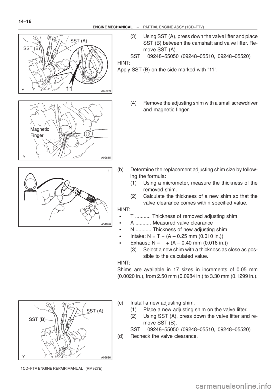
(3) Using SST (A), press down the valve lifter and place
SST (B) between the camshaft and valve lifter. Re-
move SST (A).
SST 09248±55050 (09248±05510, 09248±05520)
HINT:
Apply SST (B) on the side marked with º11º.
(4) Remove the adjusting shim with a small screwdriver
and magnetic finger.
(b) Determine the replacement adjusting shim size by follow-
ing the formula:
(1) Using a micrometer, measure the thickness of the
removed shim.
(2) Calculate the thickness of a new shim so that the
valve clearance comes within specified value.
HINT:
�T ........... Thickness of removed adjusting shim
�A ........... Measured valve clearance
�N ........... Thickness of new adjusting shim
�Intake: N = T + (A ± 0.25 mm (0.010 in.))
�Exhaust: N = T + (A ± 0.40 mm (0.016 in.))
(3) Select a new shim with a thickness as close as pos-
sible to the calculated value.
HINT:
Shims are available in 17 sizes in increments of 0.05 mm
(0.0020 in.), from 2.50 mm (0.0984 in.) to 3.30 mm (0.1299 in.).
(c) Install a new adjusting shim.
(1) Place a new adjusting shim on the valve lifter.
(2) Using SST (A), press down the valve lifter and re-
move SST (B).
SST 09248±55050 (09248±05510, 09248±05520)
(d) Recheck the valve clearance.