Page 4626 of 5135
(From September, 2003)
AVENSIS Supplement (RM1045E)
31. REMOVE INJECTION PIPE SUB −ASSY NO.1
(a) Remove the 2 upper injec")
A93406
SST
A09656
A85924
14−152
−
ENGINE MECHANICAL CAMSHAFT (1CD−FTV)(From September, 2003)
AVENSIS Supplement (RM1045E)
31. REMOVE INJECTION PIPE SUB −ASSY NO.1
(a) Remove the 2 upper injection pipe clamps from the intake manifold.
(b) Using SST, remove the injection pipe from the common
rail side.
SST 09023 −12700
(c) Using SST, remove the injection pipe from the injector side.
SST 09023 −12700
(d) After removing the fuel pipe, in order to prevent dust or
foreign objects from being introduced, cover the common
rail with vinyl tape and protect the injector inlet with a vinyl
or plastic bag.
32. REMOVE INJECTION PIPE SUB −ASSY NO.2
SST 09023 −12700
HINT:
Perform the same procedures as the injection pipe No. 1.
33. REMOVE INJECTION PIPE SUB −ASSY NO.3
SST 09023 −12700
HINT:
Perform the same procedures as the injection pipe No. 1.
34. REMOVE INJECTION PIPE SUB −ASSY NO.4
SST 09023 −12700
HINT:
Perform the same procedures as the injection pipe No. 1.
35. REMOVE VACUUM PUMP ASSY (See page 14 −108)
36. REMOVE NOZZLE LEAKAGE PIPE NO.2 (See page 14 −108)
37. REMOVE NOZZLE HOLDER SEAL
(a) Using a screwdriver, pry out the 4 nozzle holder seals.
38. REMOVE CYLINDER HEAD COVER SUB −ASSY
(a) Remove the 10 bolts, cylinder head cover and gasket.
Page 4627 of 5135
(From September, 2003)
14 −153
AVENSIS Supplement (RM1045E)
39. REMOVE NOZZLE LEAKAGE PIPE A")
A85934
A09668
A09650
1
3
2 4
5
9 6
87
14
10
11
15
13
12
A09619
−
ENGINE MECHANICAL CAMSHAFT (1CD−FTV)(From September, 2003)
14 −153
AVENSIS Supplement (RM1045E)
39. REMOVE NOZZLE LEAKAGE PIPE ASSY
(a) Remove the 4 hollow screws and bolt.
(b) Remove the nozzle leakage pipe and 4 gaskets from the
cylinder head and injector.
40. REMOVE INJECTOR ASSY (See page 11 −46)
HINT:
Since each injector assembly has characteristic fuel injecting behavior, keep them in the correct order so
that they can be returned to the original locations when reassembling.
41. REMOVE CAMSHAFT OIL SEAL RETAINER
(a) Remove the 4 bolts.
(b) Using a screwdriver, remove the oil seal retainer by pryingbetween the oil seal retainer and camshaft bearing cap.
42. REMOVE CAMSHAFT
(a) Using several steps, loosen and remove the 14 bearing cap bolts uniformly in the sequence shown in the illustra-
tion.
(b) Remove the 5 bearing caps and camshaft sub −assembly.
43. REMOVE NO.2 CAMSHAFT
(a) Remove the camshaft sub −assembly and camshaft carrier.
44. REMOVE CAMSHAFT OIL SEAL
(a) Using a screwdriver and hammer, tap out the oil seal.
Page 4633 of 5135
(From September, 2003)
14 −159
AVENSIS Supplement (RM1045E)
70. INSTALL TIMING BELT NO.1 COVER (See page 14 −138)
71. INSTALL TIMING BELT NO.2 COVER (See")
−
ENGINE MECHANICAL CAMSHAFT (1CD−FTV)(From September, 2003)
14 −159
AVENSIS Supplement (RM1045E)
70. INSTALL TIMING BELT NO.1 COVER (See page 14 −138)
71. INSTALL TIMING BELT NO.2 COVER (See page 14 −138)
72. INSTALL IDLER PULLEY SUB −ASSY (See page 14 −138)
73. INSTALL CRANKSHAFT PULLEY (See page 14 −138)
SST 09213 −54015 (09213 −70020), 09330 −00021
74. INSTALL ENGINE MOUNTING INSULATOR SUB −ASSY RH (See page 14 −138)
75. INSTALL POWER STEERING IDLE PULLEY BRACKET (See page 14 −108)
76. ADJUST V (COOLER COMPRESSOR TO CRANKSHAFT PULLEY) BELT NO.1
(See Pub. No. RM1018E on page 14 −269)
77. INSTALL INJECTOR DRIVER (See page 14 −108)
78. INSTALL AIR TUBE NO.1 (See page 14 −108)
79. INSTALL VACUUM RESERVOIR SUB −ASSY (See page 14 −108)
80. INSTALL BATTERY (See page 14 −108)
81. INSTALL AIR CLEANER ASSY (See page 14 −108)
82. INSTALL ENGINE COVER SUB −ASSY NO.1 (See page 14 −90)
83. INSTALL FRONT WHEEL RH Torque: 103 N �m (1,050 kgf �cm, 76 ft �lbf)
84. CHECK FOR FUEL LEAKS (See page 11 −46)
Page 4635 of 5135
A85616
Injector Driver
5.5 (56, 49 in.·lbf)
52 (530, 38)
Engine Mounting Insulator Sub−assy RH
52 (530, 38)x3
8.3 (85, 73 in.·lbf)
Vacuum Reservoir Sub−assy
Vacuum Warning
Switch Connector
Vacuum Hose Assy
52 (530, 38)
Union to Connector
Tube Hose
Turbo Pressure
Sensor Connector
VRV Connector
25 (255, 18)
Air Tube No. 1
N·m (kgf·cm, ft·lbf)
: Specified torque
25 (255, 18)
25 (255, 18)
6.0 (61, 53 in.·lbf)
6.0 (61, 53 in.·lbf)
Battery
Battery Tray
Air Hose No. 2
5.0 (51, 44 in.�lbf)
3.0 to 4.0 (31 to 41, 27 to 35 in.�lbf)
− ENGINE MECHANICALCAMSHAFT (1CD−FTV)(From September, 2003)
14−147
AVENSIS Supplement (RM1045E)
Page 4639 of 5135
141NI−01
A61175
A84394
A61184
14 −138
−
ENGINE MECHANICAL TIMING BELT (1CD−FTV)(From September, 2003)
AVENSIS Supplement (RM1045E)
REPLACEMENT
1. REMOVE FRONT WHEEL RH
2. REMOVE ENGINE UNDER COVER SUB −ASSY NO.1
3. REMOVE ENGINE UNDER COVER RH
4. REMOVE RADIATOR SUPPORT OPENING COVER
5. REMOVE ENGINE ROOM COVER SIDE
6. REMOVE ENGINE COVER SUB −ASSY NO.1 (See page 14 −90)
7. REMOVE INJECTOR DRIVER (See page 14 −108)
8. REMOVE V (COOLER COMPRESSOR TO CRANKSHAFT PULLEY) BELT NO.1 (See Pub. No. RM1018E on page 14 −269)
9. REMOVE GENERATOR V BELT (See Pub. No. RM1018E on page 14 −269)
10. SEPARATE PO W ER STEERI NG I DLE PULLEY BRACKET
(a) Remove the 3 bolts and power steering idle pulley brack- et.
11. DISCONNECT ENGINE WIRE
(a) Disconnect the 2 exhaust gas temperature sensor con- nectors.
12. DISCONNECT VACUUM HOSE (See page 14 −108)
13. REMOVE ENGINE MOUNTING INSULATOR SUB−ASSY RH
(a) Place a wooden block on a jack underneath the engine.
Page 4646 of 5135
(From September, 2003)
14 −145
AVENSIS Supplement (RM1045E)
(3) Remove the backing paper from a new gasket,")
A09602
Seal
Packing
Gasket
Groove
A61186
SST
−
ENGINE MECHANICAL TIMING BELT (1CD−FTV)(From September, 2003)
14 −145
AVENSIS Supplement (RM1045E)
(3) Remove the backing paper from a new gasket, then
affix the gasket to the timing belt cover as shown in
the illustration.
NOTICE:
S Affix the gasket at the center of the groove.
S At the corners, try to keep the gasket thickness uni-
form.
(4) After installing the gasket, press it down so that the
adhesive firmly sticks to the timing belt cover.
(5) If there is a gap between the ends of the gasket, use
seal packing to close the gap.
Seal packing: Part No. 08826 −00080 or equivalent
(b) Install the No. 2 timing belt cover and gasket with the 7
bolts and 7 seal washers.
Torque: 7.4 N �m (75 kgf �cm, 65 in. �lbf)
31. INSTALL IDLER PULLEY SUB −ASSY
Torque: 40 N �m (408 kgf �cm, 30 ft �lbf)
32. INSTALL CRANKSHAFT PULLEY
(a) Align the keyway of the pulley with the key located on the crankshaft, then slide the pulley into place.
(b) Using SST, install the pulley bolt.
SST 09213 −54015 (09213 −70020), 09330 −00021
Torque: 180 N·m (1,835 kgf·cm, 133 ft·lbf)
HINT:
When using the bolt (91651 −60855), a plate washer (5 mm
(0.20 in.)) must be inserted between the pulley bolt and SST.
33. INSTALL ENGINE MOUNTING INSULATOR SUB −ASSY RH
Torque: 52 N·m (530 kgf·cm, 38 ft·lbf)
34. INSTALL POWER STEERING IDLE PULLEY BRACKET (See page 14 −108)
35. ADJUST V (COOLER COMPRESSOR TO CRANKSHAFT PULLEY) BELT NO.1 (See Pub. No. RM1018E on page 14 −269)
36. INSTALL INJECTOR DRIVER (See page 14 −108)
37. INSTALL ENGINE COVER SUB −ASSY NO.1 (See page 14 −90)
38. INSTALL FRONT WHEELS Torque: 103 N �m (1,050 kgf �cm, 76 ft �lbf)
Page 4647 of 5135
141NH−01
A85614
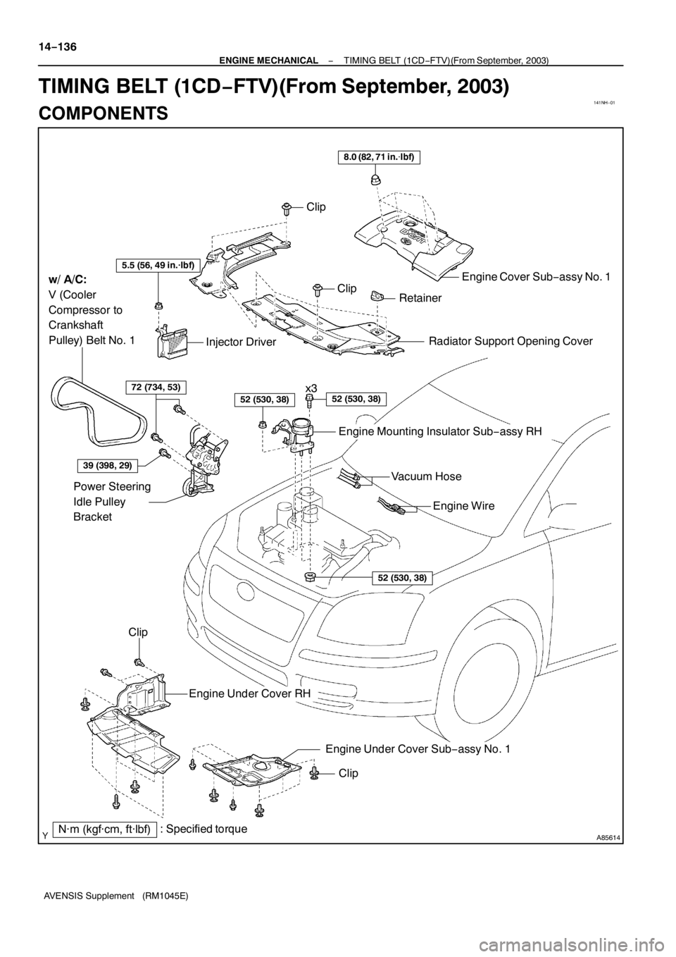
Clip
ClipRetainer
8.0 (82, 71 in.�lbf)
Engine Cover Sub−assy No. 1
Clip
Engine Under Cover RH
Clip
w/ A/C:
V (Cooler
Compressor to
Crankshaft
Pulley) Belt No. 1
Engine Mounting Insulator Sub−assy RH
x3
5.5 (56, 49 in.·lbf)
Injector Driver
39 (398, 29)
72 (734, 53)
52 (530, 38)
Power Steering
Idle Pulley
Bracket
52 (530, 38)
52 (530, 38)
Radiator Support Opening Cover
: Specified torqueN·m (kgf·cm, ft·lbf)Engine Wire Vacuum Hose
Engine Under Cover Sub−assy No. 1 14−136
− ENGINE MECHANICALTIMING BELT (1CD−FTV)(From September, 2003)
AVENSIS Supplement (RM1045E)
TIMING BELT (1CD−FTV)(From September, 2003)
COMPONENTS
Page 4655 of 5135
(From September,
2003)
AVENSIS Supplement (RM1045E)
53. REMOVE FLYWHEEL SUB −ASSY
(a) Hold the crankshaft with SST.")
A61186
SST
A84289
14−11 4−
ENGINE MECHANICAL PARTIAL ENGINE ASSY (1CD −FTV)(From September,
2003)
AVENSIS Supplement (RM1045E)
53. REMOVE FLYWHEEL SUB −ASSY
(a) Hold the crankshaft with SST. SST 09213 −54015 (09213 −70020), 09330 −00021
(b) Using a Torx socket wrench (T55), remove the 8 Torx
screws and flywheel.
54. REMOVE REAR END PLATE
(a) Remove the 2 bolts and rear end plate.
55. REMOVE DRIVE SHAFT BEARING BRACKET
56. REMOVE ENGINE MOUNTING BRACKET FR
57. REMOVE ENGINE MOUNTING BRACKET RR
58. REMOVE GLOW PLUG ASSY (See Pub. No. RM1018E on page 19 −33)
59. REMOVE GENERATOR V BELT (See Pub. No. RM1018E on page 14 −269)
60. REMOVE CRANKSHAFT PULLEY (See page 14 −138)
SST 09213 −54015 (09213 −70020), 09330 −00021, 09950 −50013 (09951 −05010, 09952 −05010,
09953 −05020, 09954 −05031)
61. REMOVE IDLER PULLEY SUB −ASSY (See page 14 −138)
62. REMOVE TIMING BELT NO.2 COVER (See page 14 −138)
63. REMOVE TIMING BELT NO.1 COVER (See page 14 −138)
64. REMOVE TIMING BELT GUIDE
65. REMOVE TRANSVERSE ENGINE ENGINE MOUNTING BRACKET (See page 14 −138)
66. SET NO. 1 CYLINDER TO TDC/COMPRESSION (See page 14 −138)
67. REMOVE TIMING BELT (See page 14 −138)
HINT:
If reusing the timing belt, draw an arrow on the belt which indicates the engine revolution direction and put
match marks on the pulleys and belt before removing. This operation will be very helpful when reinstalling
the timing belt.
68. REMOVE GENERATOR ASSY (See Pub. No. RM1018E on page 19 −29)
69. REMOVE GENERATOR BRACKET NO.1
(a) Remove the 2 bolts and generator bracket.

52 (530, 38)
Engine Mounting Insulator Sub−assy RH
52 (530, 38)x3
8.3 (85, 73 in.·lbf)
Vacuum Reservoir Sub−assy
Vacuum Warning
Switch Connector
Vacuu")
(From September, 2003)
AVENSIS Supplement (RM1045E)
REPLACEMENT
1. REMOVE FRONT WHEEL RH
2. REMOVE ENGINE UNDER")