Page 4670 of 5135
(From September,
2003)14 −129
AVENSIS Supplement (RM1045E)
166. INSTALL V −RIBBED BELT TENSIONER ASSY
Torque: 31 N")
A61186
SST
A57108
Adhesive
−
ENGINE MECHANICAL PARTIAL ENGINE ASSY (1CD −FTV)(From September,
2003)14 −129
AVENSIS Supplement (RM1045E)
166. INSTALL V −RIBBED BELT TENSIONER ASSY
Torque: 31 N �m (316 kgf �cm, 23 ft �lbf)
167. INSTALL GENERATOR BRACKET NO.1 Torque: 37 N �m (377 kgf �cm, 27 ft �lbf)
168. INSTALL GENERATOR ASSY (See Pub. No. RM1018E on page 19 −29)
169. SET NO. 1 CYLINDER TO TDC/COMPRESSION (See page 14 −138)
SST 09960 −10010 (09962 −01000, 09963 −01000)
170. INSTALL TIMING BELT (See page 14 −138)
171. CHECK VALVE TIMING (See page 14 −138)
172. INSTALL TRANSVERSE ENGINE ENGINE MOUNTING BRACKET (See page 14 −138)
173. INSTALL TIMING BELT GUIDE (See page 14 −138)
174. INSTALL TIMING BELT NO.1 COVER (See page 14 −138)
175. INSTALL TIMING BELT NO.2 COVER (See page 14 −138)
176. INSTALL IDLER PULLEY SUB −ASSY
Torque: 40 N �m (408 kgf �cm, 30 ft �lbf)
177. INSTALL CRANKSHAFT PULLEY (See page 14 −138)
SST 09213 −54015 (09213 −70020), 09330 −00021
178. INSTALL GLOW PLUG ASSY (See Pub. No. RM1018E on page 19 −33)
179. INSTALL ENGINE MOUNTING BRACKET RR
Torque: 64 N �m (653 kgf �cm, 47 ft �lbf)
180. INSTALL ENGINE MOUNTING BRACKET FR Torque: 64 N �m (653 kgf �cm, 47 ft �lbf)
181. INSTALL DRIVE SHAFT BEARING BRACKET Torque: 64 N �m (653 kgf �cm, 47 ft �lbf)
182. INSTALL REAR END PLATE Torque: 8.4 N �m (86 kgf �cm, 74 in. �lbf)
183. INSTALL FLYWHEEL SUB −ASSY
(a) Using SST, hold the crankshaft. SST 09213 −54015 (09213 −70020), 09330 −00021
(b) Clean the bolts and their bolt holes.
(c) Apply adhesive to the 2 or 3 threads of the bolt end. Adhesive: Part No. 08833 −00070, THREE BOND 1324
or equivalent
Page 4685 of 5135
(Fro")
141ND−01
A57063
Measure Point for Belt
Deflection and Tension
Alternator
Crankshaft Compressor
P/SP/S
Alternator Crankshaft
A/C Equipped
A/C Not Equipped
−
ENGINE MECHANICAL ENGINE (1CD−FTV)(From September, 2003)
14 −87
AVENSIS Supplement (RM1045E)
ENGINE (1CD −FTV)(From September, 2003)
INSPECTION
1. INSPECT ENGINE COOLANT (See page 16 −15)
2. INSPECT ENGINE OIL (See page 17 −9)
3. INSPECT BATTERY (See Pub. No. RM1018E on page 19 −26)
4. INSPECT AIR CLEANER FILTER ELEMENT SUB −ASSY
5. INSPECT DRIVE BELT
(a) Inspect the vane pump V −ribbed belt.
(1) Measure the belt deflection.
Pressing force: 98 N (10 kgf, 22 lbf)
New Belt
mm (in.)Used Belt mm (in.)
A/C Equipped8.0 to 10.5
(0.31 to 0.41)10.5 to 12.5
(0.41 to 0.49)
A/C Not Equipped10 to 12
(0.39 to 0.47)14 to 17
(0.55 to 0.67)
(2) Measure the belt tension.
New Belt
N (kgf, lbf)Used Belt
N (kgf, lbf)
A/C Equipped647 to 843
(66 to 86, 145 to 189)441 to 637
(45 to 65, 99 to 143)
A/C Not Equipped686 to 784
(70 to 80, 154 to 176)294 to 441
(30 to 45, 66 to 99)
NOTICE:
SCheck the drive belt deflection at the specified point.
SWhen installing a new belt, set its tension value as
specified.
SWhen inspecting the belt which has been used for
over 5 minutes, apply the specifications of ”Used
Belt.”
SWhen reinstalling the belt which has been used for
over 5 minutes, adjust its deflection and tension to
the intermediate value of each specification of ”Used
Belt.”
SThe V −ribbed belt tension and deflection should be
checked after 2 revolutions of engine cranking.
SWhen using a belt tension gauge, confirm the accura-
cy by using a master gauge first.
Page 4688 of 5135

AVENSIS Supplement (RM1045E)
ENGINE REAR OIL SEAL (2AZ −FSE)
REPLACEMENT
1. REMOVE AUTOMATI")
141BS−02
A77421
Cut Position
A77422SST
14
−86
−
ENGINE MECHANICAL ENGINE REAR OIL SEAL (2AZ −FSE)
AVENSIS Supplement (RM1045E)
ENGINE REAR OIL SEAL (2AZ −FSE)
REPLACEMENT
1. REMOVE AUTOMATIC TRANSAXLE ASSY (See page 40 −3)
2. REMOVE DRIVE PLATE & RING GEAR SUB −ASSY (See page 14 −23)
SST 09213 −54015 (91651 −60855), 09330 −00021
3. REMOVE ENGINE REAR OIL SEAL
(a) Using a knife, cut off the engine rear oil seal lip.
(b) Using a screwdriver with the tip wrapped in tape, pry out the engine rear oil seal.
HINT:
After the removal, check that the crankshaft is not damaged.
If damaged, smooth the surface with 400 −grit sandpaper.
4. INSTALL ENGINE REAR OIL SEAL
(a) Apply MP grease to a new engine rear oil seal lip.
NOTICE:
Keep the lip off foreign materials.
(b) Using SST and a hammer, tap in the engine rear oil seal until its surface is flush with the engine rear oil seal retain-
er edge.
SST 09223 −15030, 09950 −70010 (09951 −07100)
NOTICE:
Wipe off extra grease on the crankshaft.
5. INSTALL DRIVE PLATE & RING GEAR SUB −ASSY (See page 14 −23)
SST 09213 −54015 (91651 −60855), 09330 −00021
6. INSTALL AUTOMATIC TRANSAXLE ASSY (See page 40 −3)
Page 4689 of 5135
14 −85
AVENSIS Supplement (RM1045E)
TIMING GEAR CASE OR TIMING CHAIN CASE O")
141NC−01
Cut Position
A13332
A77419
SST
−
ENGINE MECHANICAL TIMING GEAR CASE OR TIMING CHAIN CASE OIL
SEAL (2AZ−FSE)14 −85
AVENSIS Supplement (RM1045E)
TIMING GEAR CASE OR TIMING CHAIN CASE OIL
SEAL (2AZ −FSE)
REPLACEMENT
1. REMOVE FRONT WHEEL RH
2. REMOVE RADIATOR SUPPORT OPENING COVER (See page 14 −23)
3. REMOVE ENGINE ROOM COVER SIDE (See page 14 −23)
4. REMOVE ENGINE UNDER COVER LH (See page 14 −23)
5. REMOVE ENGINE UNDER COVER NO.4 RH (See page 14 −23)
6. REMOVE ENGINE UNDER COVER RH (See page 14 −23)
7. REMOVE ENGINE COVER SUB −ASSY NO.1 (See page 14 −45)
8. REMOVE FAN AND GENERATOR V BELT (See page 14 −5)
SST 09249 −63010
9. REMOVE CRANKSHAFT PULLEY (See page 14 −45)
SST 09213 −54015 (91651 −60855), 09330 −00021, 09950 −50013 (09951 −05010, 09952 −05010,
09953 −05020, 09954 −05021)
10. REM O VE TI M I NG G EAR CASE O R T I M I NG CHAI NCASE OIL SEAL
(a) Using a screwdriver with tip wrapped in the tape, pry out the oil seal.
HINT:
After removal, check that the crankshaft is not damaged.
If damaged, smooth the surface with 400 −grit sandpaper.
11. I NSTALL TI M I NG G EAR CASE O R T I M I NG CHAI N CASE OIL SEAL
(a) Apply MP grease to a new oil seal lip.
NOTICE:
Keep the lip off foreign materials.
(b) Using SST and a hammer, tap in the oil seal until its sur- face is flush with the rear oil seal retainer edge.
SST 09223 −22010
NOTICE:
Wipe off extra grease on the crankshaft.
12. INSTALL CRANKSHAFT PULLEY (See page 14 −45)
SST 09213 −54015 (91651 −60855), 09330 −00021
13. INSTALL FAN AND GENERATOR V BELT (See page 14 −5)
SST 09249 −63010
14. INSTALL ENGINE COVER SUB −ASSY NO.1
Torque: 7.0 N �m (71 kgf �cm, 62 in. �lbf)
15. INSTALL FRONT WHEEL RH Torque: 103 N �m (1,050 kgf �cm, 76 ft �lbf)
16. CHECK FOR ENGINE OIL LEAKS
Page 4702 of 5135
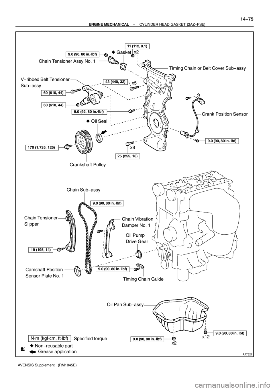
A77327
N·m (kgf·cm, ft·lbf)
: Specified torque
zNon−reusable partzGasket
9.0 (90, 80 in.�lbf)
Chain Tensioner Assy No. 1
Timing Chain or Belt Cover Sub−assy
Crank Position Sensor
9.0 (90, 80 in.�lbf)
V−ribbed Belt Tensioner
Sub−assy
60 (610, 44)
60 (610, 44)
9.0 (92, 80 in.�lbf)
170 (1,735, 125)
Crankshaft Pulley
Chain Sub−assy
25 (255, 18)
Chain Tensioner
Slipper
19 (195, 14)
Camshaft Position
Sensor Plate No. 1
Oil Pump
Drive Gear
Chain Vibration
Damper No. 1
zOil Seal
Timing Chain Guide
9.0 (90, 80 in.�lbf)
Oil Pan Sub−assy
9.0 (90, 80 in.�lbf)
9.0 (90, 80 in.�lbf)
11 (112, 8.1)
43 (440, 32)
9.0 (90, 80 in.�lbf)
x2
x5
x8
x2x12
Grease application
− ENGINE MECHANICALCYLINDER HEAD GASKET (2AZ−FSE)
14−75
AVENSIS Supplement (RM1045E)
Page 4710 of 5135
A93082
87 (887, 64)
37 (377, 27)
52 (530, 38)
87 (887, 64)52 (530, 38)
52 (530, 38)
52 (530, 38)52 (530, 38)
52 (530, 38)
133 (1,356, 83)
80 (816, 59)
80 (816, 59)
133 (1,356, 83)
45 (459, 33)
133 (1,356, 83)
Engine Mounting Bracket No. 2 RH
Transverse Engine
Engine Mounting Insulator
Front Suspension Brace RH
Front Suspension
Brace LH
Front Drive Shaft Assy RH
Front Drive Shaft Assy LH Engine Assembly
with Transaxle
Front Suspension Crossmember
w/ Center Member
N·m (kgf·cm, ft·lbf)
: Specified torque
Vane Pump Assy
113 (1,152, 83)
87 (887, 64)
x2
− ENGINE MECHANICALPARTIAL ENGINE ASSY (2AZ−FSE)
14−15
AVENSIS Supplement (RM1045E)
Page 4711 of 5135
A89207
Engine Assy
Drive Shaft Bearing Bracket
Cover
Drive Plate & Ring Gear
Sub−assy x6
Wire Clamp Bracket
Starter Wire Starter Assy
34 (347, 25)
44 (449, 33)
98 (1,000, 72)
46 (469, 34)
13 (132, 10)
x8
N·m (kgf·cm, ft·lbf)
: Specified torque
Automatic Transaxle
46 (469, 34)
46 (469, 34)
37 (378, 27)
37 (378, 27)
64 (653, 47)
41 (418, 30)
64 (653, 47)
64 (653, 47)
Front
Spacer
Rear
Spacer
14−16
− ENGINE MECHANICALPARTIAL ENGINE ASSY (2AZ−FSE)
AVENSIS Supplement (RM1045E)
Page 4731 of 5135

AVENSIS Supplement (RM1045E)
OVERHAUL
HINT:
Overhaul the RH side follow")
300N6−01
C53220F45751
SST
F13686
Hold
Turn
C80291
F44775
30−4
− DRIVE SHAFT / PROPELLER SHAFTFRONT DRIVE SHAFT (2AZ−FSE)
AVENSIS Supplement (RM1045E)
OVERHAUL
HINT:
Overhaul the RH side following the same procedure as for the LH side.
1. DRAIN AUTOMATIC TRANSAXLE FLUID (A/T TRANSAXLE)
(a) Remove the drain plug and gasket, and then drain the ATF.
(b) Install a new gasket and drain plug.
Torque: 49 N�m (500 kgf�cm, 36 ft�lbf)
2. REMOVE FRONT WHEEL
3. REMOVE ENGINE UNDER COVER LH
4. SEPARATE FRONT AXLE HUB LH NUT
(a) Using SST and a hammer, unstake the staked part of the
nut.
SST 09930−00010
(b) While applying the brake, remove the axle hub LH nut.
NOTICE:
Loosen the staked part of the lock nut completely, other-
wise the screw of the drive shaft may become damaged.
5. SEPARATE FRONT STABILIZER LINK ASSY LH
(a) Remove the nut and separate the front stabilizer link assy
LH from the shock absorber assy LH.
HINT:
If the ball joint turns together with the nut, use a hexagon
wrench (6 mm) to hold the stud.
6. DISCONNECT SPEED SENSOR FRONT LH
(a) Remove the bolt, and disconnect the speed sensor wire
and flexible hose from the shock absorber.
(b) Remove the bolt, and disconnect the speed sensor from
the steering knuckle.
NOTICE:
SBe careful not to damage the speed sensor.
SPrevent foreign matter from adhering to the speed
sensor.

37 (377, 27)
52 (530, 38)
87 (887, 64)52 (530, 38)
52 (530, 38)
52 (530, 38)52 (530, 38)
52 (530, 38)
133 (1,356, 83)
80 (816, 59)
80 (816, 59)
133 (1,356, 83)
45 (459, 33)
133 (1,")

44 (449, 33)
98 (1,000, 72)
46 (469, 34)
13 (132, 1")