Page 3750 of 5135
C69639
SST
C69640
C69641
SST
C69642
41±62
± MANUAL TRANSMISSION/TRANSAXLEOUTPUT SHAFT ASSY (E355/E356)
E355,E356 M/T REPAIR MANUAL (RM867E)
4. INSPECT 2ND GEAR RADIAL CLEARANCE
(a) Using a dial indicator, measure the 2nd gear radial clear-
ance.
Standard clearance:mm (in.)
BearingStandard clearance
KOYO made0.009 ± 0.053
(0.0004 ± 0.0021)
NSK made0.009 ± 0.051
(0.0004 ± 0.0020)
If the clearance is out of the specification, replace the 2nd gear
needle roller bearing.
5. REMOVE 4TH DRIVEN GEAR
(a) Using SST and a press, remove the output shaft bearing
rear (inner race) and 4th driven gear.
SST 09950±00020
6. REMOVE OUTPUT GEAR SPACER
(a) Remove the out put gear spacer from the output shaft.
7. REMOVE 2ND GEAR
(a) Using SST and a press, remove the 3rd driven gear and
2nd gear from the out put shaft.
SST 09950±00020
Page 3755 of 5135

C70507
C69671
C69672
SST
C69674
± MANUAL TRANSMISSION/TRANSAXLEOUTPUT SHAFT ASSY (E355/E356)
41±67
E355,E356 M/T REPAIR MANUAL (RM867E)
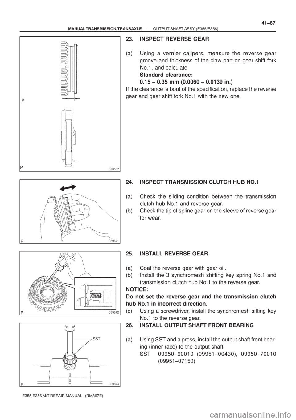
23. INSPECT REVERSE GEAR
(a) Using a vernier calipers, measure the reverse gear
groove and thickness of the claw part on gear shift fork
No.1, and calculate
Standard clearance:
0.15 ± 0.35 mm (0.0060 ± 0.0139 in.)
If the clearance is bout of the specification, replace the reverse
gear and gear shift fork No.1 with the new one.
24. INSPECT TRANSMISSION CLUTCH HUB NO.1
(a) Check the sliding condition between the transmission
clutch hub No.1 and reverse gear.
(b) Check the tip of spline gear on the sleeve of reverse gear
for wear.
25. INSTALL REVERSE GEAR
(a) Coat the reverse gear with gear oil.
(b) Install the 3 synchromesh shifting key spring No.1 and
transmission clutch hub No.1 to the reverse gear.
NOTICE:
Do not set the reverse gear and the transmission clutch
hub No.1 in incorrect direction.
(c) Using a screwdriver, install the synchromesh sifting key
No.1 to the reverse gear.
26. INSTALL OUTPUT SHAFT FRONT BEARING
(a) Using SST and a press, install the output shaft front bear-
ing (inner race) to the output shaft.
SST 09950±60010 (09951±00430), 09950±70010
(09951±07150)
Page 3758 of 5135
SST
SST
C69676
C69641
SST
SST
C69677
SST
SST
C69678
41±70
± MANUAL TRANSMISSION/TRANSAXLEOUTPUT SHAFT ASSY (E355/E356)
E355,E356 M/T REPAIR MANUAL (RM867E)
37. INSTALL 3RD DRIVEN GEAR
(a) Using SST and a press, install the 3rd driven gear to the
output shaft.
SST 09608±00071, 09950±60010 (09951±00320),
09950±70010 (09951±07100)
38. INSTALL OUTPUT GEAR SPACER
(a) install the output gear spacer to the output shaft.
39. INSTALL 4TH DRIVEN GEAR
(a) Using SST and a press, install the 4th driven gear to the
output shaft.
SST 09608±00071, 09950±60010 (09951±00320),
09950±70010 (09951±07100)
40. INSTALL OUTPUT SHAFT FRONT BEARING
(a) Using SST and a press, install the output shaft front bear-
ing (inner race) to the output shaft.
SST 09506±30012, 09950±60010 (09951±00320),
09950±70010 (09951±07100)
Page 3761 of 5135
C69549
C70515
SST
C69550
C69551
± MANUAL TRANSMISSION/TRANSAXLEINPUT SHAFT ASSY (E355/E356)
41±51
E355,E356 M/T REPAIR MANUAL (RM867E)
4. INSPECT 3RD GEAR RADIAL CLEARANCE
(a) Using a dial indicator, measure the 3rd gear radial clear-
ance.
Standard clearance: mm (in.)
BearingStandard clearance
KOYO made0.009 ± 0.053
(0.0004 ± 0.0021)
NSK made0.009 ± 0.051
(0.0004 ± 0.0020)
If the clearance exceeds the maximum, replace the 3rd gear
needle roller bearing.
5. REMOVE 4TH GEAR
(a) Fix the input shaft assy and soft jaws to the valse.
(b) Using a 2 screwdrivers and a hammer, remove the input
shaft rear bearing shaft snap ring from the input shaft.
NOTICE:
Using a waste to prevent the snap ring from being scat-
tered.
(c) Using SST and a press, remove the input shaft rear bear-
ing and 4th gear.
SST 09950±00020
NOTICE:
Do not tighten SST excessively.
6. REMOVE 4TH GEAR NEEDLE ROLLER BEARING
(a) Remove the 4th gear needle roller bearing from the input
shaft.
Page 3762 of 5135
C69552
C69553
C69615
SST
C69616
C69617
41±52
± MANUAL TRANSMISSION/TRANSAXLEINPUT SHAFT ASSY (E355/E356)
E355,E356 M/T REPAIR MANUAL (RM867E)
7. REMOVE 2ND SYNCHRONIZER OUTER RING
(a) Remove the 2nd synchronizer outer ring from the trans-
mission clutch hub No.2.
8. REMOVE 4TH GEAR BEARING SPACER
(a) Remove the 4th gear bearing spacer from the transmis-
sion clutch hub No.2.
9. REMOVE 3RD GEAR
(a) Using 2 screwdrivers and a hammer, remove the clutch
hub No.2 setting shaft snap ring from the input shaft.
NOTICE:
Using a waste to prevent the snap ring from being scat-
tered.
(b) Using SST and a press, remove the transmission clutch
hub No.2 and 3rd gear from the input shaft.
SST 09950±00020
NOTICE:
Do not tighten SST excessively.
10. REMOVE 3RD GEAR NEEDLE ROLLER BEARING
(a) Remove the 3rd gear needle roller bearing from the input
shaft.
Page 3766 of 5135

C70506
SST
C69767
C69660
C69617
41±56
± MANUAL TRANSMISSION/TRANSAXLEINPUT SHAFT ASSY (E355/E356)
E355,E356 M/T REPAIR MANUAL (RM867E)
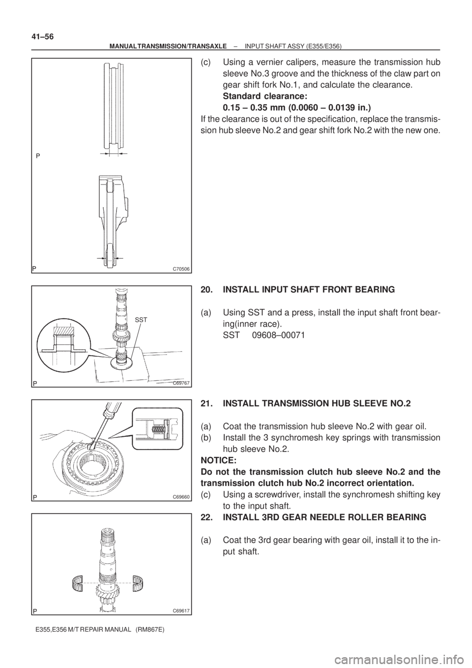
(c) Using a vernier calipers, measure the transmission hub
sleeve No.3 groove and the thickness of the claw part on
gear shift fork No.1, and calculate the clearance.
Standard clearance:
0.15 ± 0.35 mm (0.0060 ± 0.0139 in.)
If the clearance is out of the specification, replace the transmis-
sion hub sleeve No.2 and gear shift fork No.2 with the new one.
20. INSTALL INPUT SHAFT FRONT BEARING
(a) Using SST and a press, install the input shaft front bear-
ing(inner race).
SST 09608±00071
21. INSTALL TRANSMISSION HUB SLEEVE NO.2
(a) Coat the transmission hub sleeve No.2 with gear oil.
(b) Install the 3 synchromesh key springs with transmission
hub sleeve No.2.
NOTICE:
Do not the transmission clutch hub sleeve No.2 and the
transmission clutch hub No.2 incorrect orientation.
(c) Using a screwdriver, install the synchromesh shifting key
to the input shaft.
22. INSTALL 3RD GEAR NEEDLE ROLLER BEARING
(a) Coat the 3rd gear bearing with gear oil, install it to the in-
put shaft.
Page 3782 of 5135

A62837SST
A10076
A30848
± ENGINE MECHANICALPARTIAL ENGINE ASSY (1ZZ±FE/3ZZ±FE)
14±5
1ZZ±FE,3ZZ±FE ENGINE REPAIR MANUAL
(RM923E)
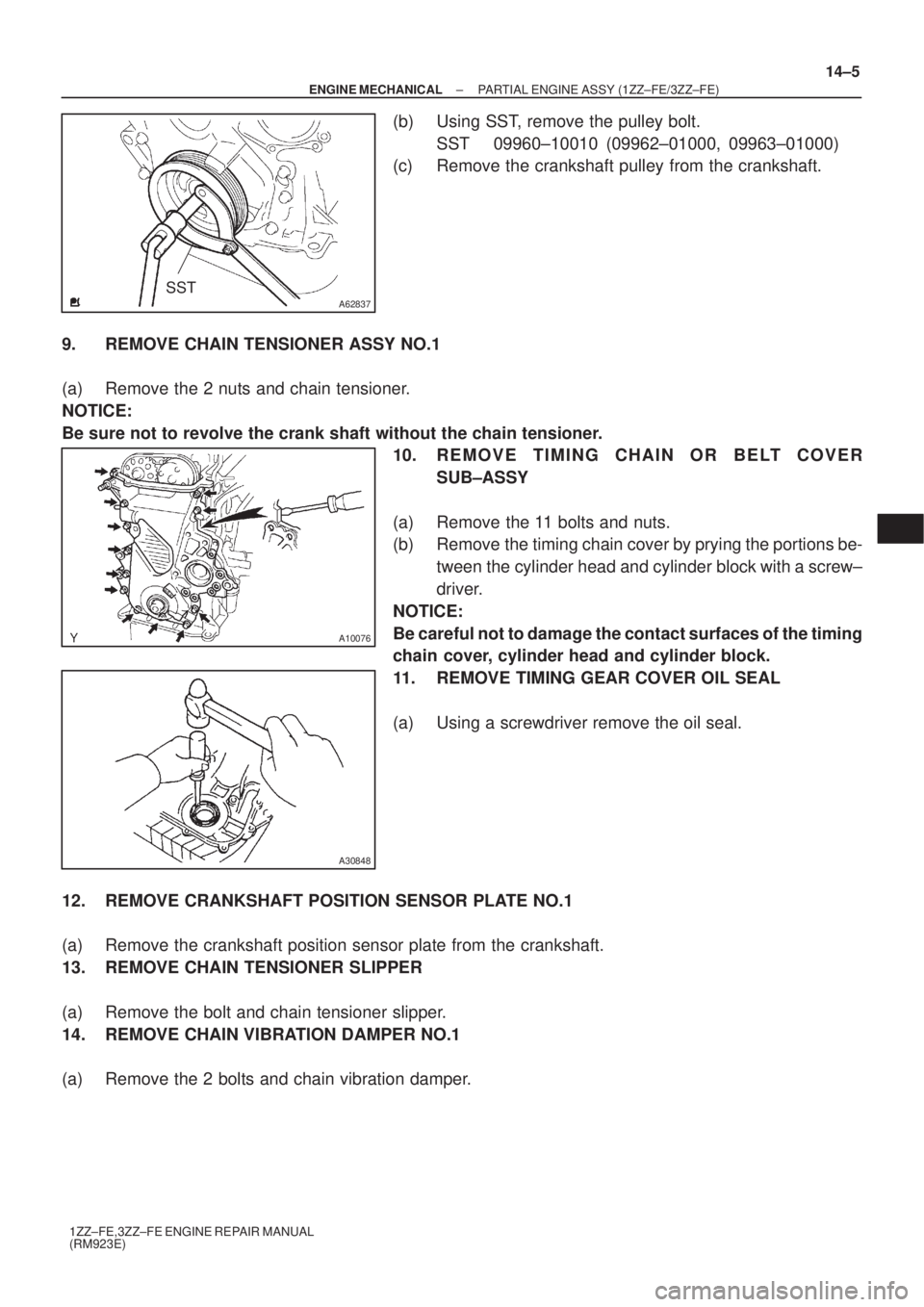
(b) Using SST, remove the pulley bolt.
SST 09960±10010 (09962±01000, 09963±01000)
(c) Remove the crankshaft pulley from the crankshaft.
9. REMOVE CHAIN TENSIONER ASSY NO.1
(a) Remove the 2 nuts and chain tensioner.
NOTICE:
Be sure not to revolve the crank shaft without the chain tensioner.
10. REMOVE TIMING CHAIN OR BELT COVER
SUB±ASSY
(a) Remove the 11 bolts and nuts.
(b) Remove the timing chain cover by prying the portions be-
tween the cylinder head and cylinder block with a screw±
driver.
NOTICE:
Be careful not to damage the contact surfaces of the timing
chain cover, cylinder head and cylinder block.
11. REMOVE TIMING GEAR COVER OIL SEAL
(a) Using a screwdriver remove the oil seal.
12. REMOVE CRANKSHAFT POSITION SENSOR PLATE NO.1
(a) Remove the crankshaft position sensor plate from the crankshaft.
13. REMOVE CHAIN TENSIONER SLIPPER
(a) Remove the bolt and chain tensioner slipper.
14. REMOVE CHAIN VIBRATION DAMPER NO.1
(a) Remove the 2 bolts and chain vibration damper.
Page 3783 of 5135

A30857
A62814
4 2531
A32167
A62190
Advance
Side Path Retard Side
Path
Open
Close
Rubber Vinyl Tape Open Close
14±6
± ENGINE MECHANICALPARTIAL ENGINE ASSY (1ZZ±FE/3ZZ±FE)
1ZZ±FE,3ZZ±FE ENGINE REPAIR MANUAL
(RM923E)
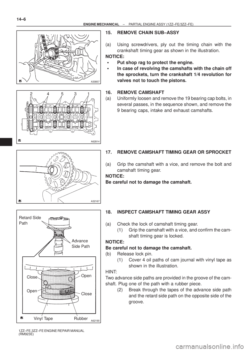
15. REMOVE CHAIN SUB±ASSY
(a) Using screwdrivers, ply out the timing chain with the
crankshaft timing gear as shown in the illustration.
NOTICE:
�Put shop rag to protect the engine.
�In case of revolving the camshafts with the chain off
the sprockets, turn the crankshaft 1/4 revolution for
valves not to touch the pistons.
16. REMOVE CAMSHAFT
(a) Uniformly loosen and remove the 19 bearing cap bolts, in
several passes, in the sequence shown, and remove the
9 bearing caps, intake and exhaust camshafts.
17. REMOVE CAMSHAFT TIMING GEAR OR SPROCKET
(a) Grip the camshaft with a vice, and remove the bolt and
camshaft timing gear.
NOTICE:
Be careful not to damage the camshaft.
18. INSPECT CAMSHAFT TIMING GEAR ASSY
(a) Check the lock of camshaft timing gear.
(1) Grip the camshaft with a vice, and confirm the cam-
shaft timing gear is locked.
NOTICE:
Be careful not to damage the camshaft.
(b) Release lock pin.
(1) Cover 4 oil paths of cam journal with vinyl tape as
shown in the illustration.
HINT:
Two advance side paths are provided in the groove of the cam-
shaft. Plug one of the path with a rubber piece.
(2) Break through the tapes of the advance side path
and the retard side path on the opposite side of the
groove.