Page 3578 of 5135

D30558
D30559
D30560
D30561
C80584
± MANUAL TRANSMISSION/TRANSAXLESHIFT & SELECT LEVER SHAFT ASSY (C250)
41±63
C250 M/T REPAIR MANUAL (RM1020E)
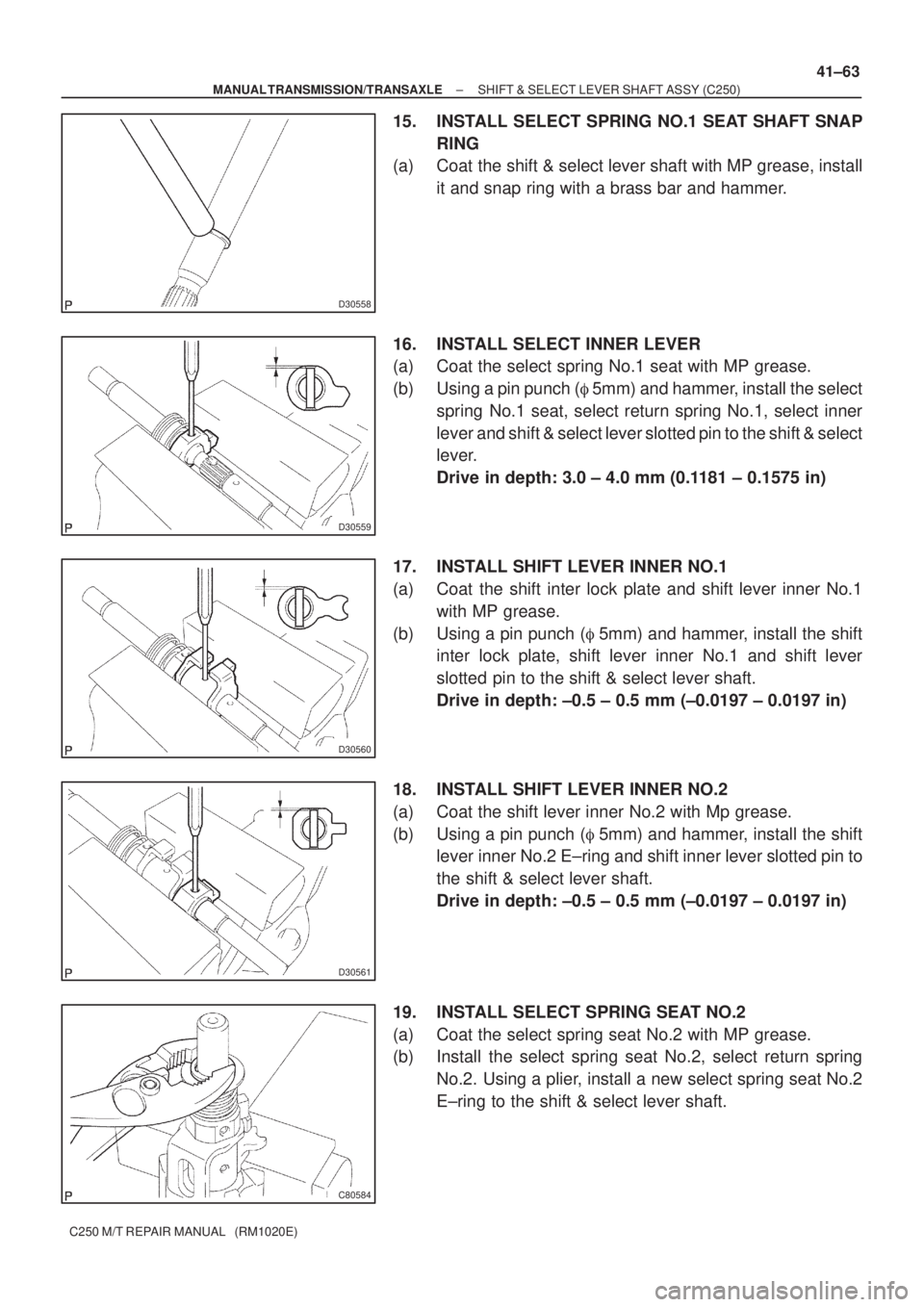
15. INSTALL SELECT SPRING NO.1 SEAT SHAFT SNAP
RING
(a) Coat the shift & select lever shaft with MP grease, install
it and snap ring with a brass bar and hammer.
16. INSTALL SELECT INNER LEVER
(a) Coat the select spring No.1 seat with MP grease.
(b) Using a pin punch (�5mm) and hammer, install the select
spring No.1 seat, select return spring No.1, select inner
lever and shift & select lever slotted pin to the shift & select
lever.
Drive in depth: 3.0 ± 4.0 mm (0.1181 ± 0.1575 in)
17. INSTALL SHIFT LEVER INNER NO.1
(a) Coat the shift inter lock plate and shift lever inner No.1
with MP grease.
(b) Using a pin punch (�5mm) and hammer, install the shift
inter lock plate, shift lever inner No.1 and shift lever
slotted pin to the shift & select lever shaft.
Drive in depth: ±0.5 ± 0.5 mm (±0.0197 ± 0.0197 in)
18. INSTALL SHIFT LEVER INNER NO.2
(a) Coat the shift lever inner No.2 with Mp grease.
(b) Using a pin punch (�5mm) and hammer, install the shift
lever inner No.2 E±ring and shift inner lever slotted pin to
the shift & select lever shaft.
Drive in depth: ±0.5 ± 0.5 mm (±0.0197 ± 0.0197 in)
19. INSTALL SELECT SPRING SEAT NO.2
(a) Coat the select spring seat No.2 with MP grease.
(b) Install the select spring seat No.2, select return spring
No.2. Using a plier, install a new select spring seat No.2
E±ring to the shift & select lever shaft.
Page 3607 of 5135

4002K±01
C67867
C67868
C67869
C67870
40±58
± AUTOMATIC TRANSMISSION / TRANSINTERMEDIATE SHAFT ASSY (U34#E Series)
U340E A/T REPAIR MANUAL (RM824E)
INTERMEDIATE SHAFT ASSY (U34#E Series)
OVERHAUL
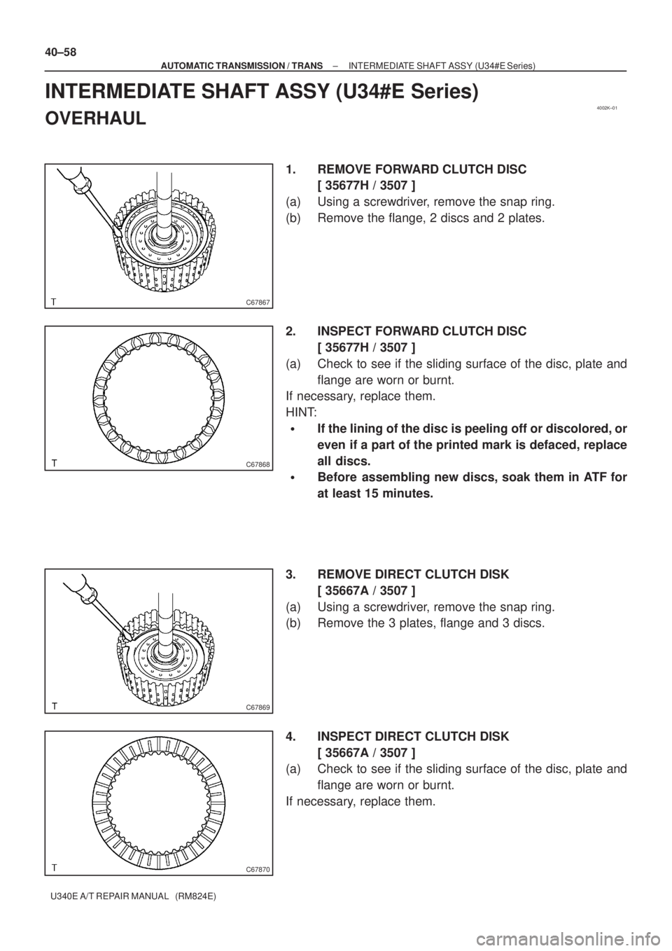
1. REMOVE FORWARD CLUTCH DISC
[ 35677H / 3507 ]
(a) Using a screwdriver, remove the snap ring.
(b) Remove the flange, 2 discs and 2 plates.
2. INSPECT FORWARD CLUTCH DISC
[ 35677H / 3507 ]
(a) Check to see if the sliding surface of the disc, plate and
flange are worn or burnt.
If necessary, replace them.
HINT:
�If the lining of the disc is peeling off or discolored, or
even if a part of the printed mark is defaced, replace
all discs.
�Before assembling new discs, soak them in ATF for
at least 15 minutes.
3. REMOVE DIRECT CLUTCH DISK
[ 35667A / 3507 ]
(a) Using a screwdriver, remove the snap ring.
(b) Remove the 3 plates, flange and 3 discs.
4. INSPECT DIRECT CLUTCH DISK
[ 35667A / 3507 ]
(a) Check to see if the sliding surface of the disc, plate and
flange are worn or burnt.
If necessary, replace them.
Page 3609 of 5135

C68212
D25110
C68213
C67875
C67876
40±60
± AUTOMATIC TRANSMISSION / TRANSINTERMEDIATE SHAFT ASSY (U34#E Series)
U340E A/T REPAIR MANUAL (RM824E)
8. INSPECT DIRECT CLUTCH PISTON SUB±ASSY
[ 35606A / 3507 ]
(a) Shake the direct clutch pin and check that a check ball is
not stuck.
(b) Apply low pressure air to the check ball with compressed
air and check that no air leak is identified.
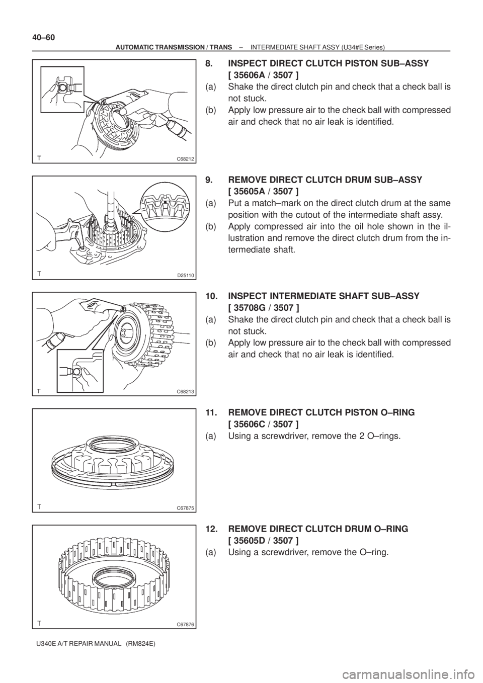
9. REMOVE DIRECT CLUTCH DRUM SUB±ASSY
[ 35605A / 3507 ]
(a) Put a match±mark on the direct clutch drum at the same
position with the cutout of the intermediate shaft assy.
(b) Apply compressed air into the oil hole shown in the il-
lustration and remove the direct clutch drum from the in-
termediate shaft.
10. INSPECT INTERMEDIATE SHAFT SUB±ASSY
[ 35708G / 3507 ]
(a) Shake the direct clutch pin and check that a check ball is
not stuck.
(b) Apply low pressure air to the check ball with compressed
air and check that no air leak is identified.
11. REMOVE DIRECT CLUTCH PISTON O±RING
[ 35606C / 3507 ]
(a) Using a screwdriver, remove the 2 O±rings.
12. REMOVE DIRECT CLUTCH DRUM O±RING
[ 35605D / 3507 ]
(a) Using a screwdriver, remove the O±ring.
Page 3636 of 5135
4006Z±01
D08032
D08033
D08034
40±14
± AUTOMATIC TRANSMISSION / TRANSAUTOMATIC TRANSAXLE ASSY (U241E)
U241E A/T REPAIR MANUAL (RM840U)
AUTOMATIC TRANSAXLE ASSY (U241E)
OVERHAUL
1. REMOVE SPEEDOMETER DRIVEN HOLE (ATM) COVER SUB±ASSY
(a) Remove the bolt and speedometer driven hole cover sub±assy from the transaxle assy.
(b) Remove the O±ring from the speedometer driven hole cover.
2. REMOVE PARK/NEUTRAL POSITION SWITCH ASSY
(a) Remove the nut, washer and control shaft lever.
(b) Using a screwdriver, unstake the nut stopper and remove
the lock nut and stopper.
(c) Remove the 2 bolts and pull out the park/neutral position
switch.
3. REMOVE BREATHER PLUG HOSE
(a) Remove the breather plug hose from the breather No. 2 plug.
Page 3643 of 5135
D03564
D03565
D03905
D03566
± AUTOMATIC TRANSMISSION / TRANSAUTOMATIC TRANSAXLE ASSY (U241E)
40±21
U241E A/T REPAIR MANUAL (RM840U)
(b) Using a pin punch and hammer, drive out the manual
valve lever shaft spring pin.
HINT:
Slowly drive out the pin so that it will not fall into the transaxle
case.
(c) Remove the manual valve lever shaft and manual valve
lever.
27. REMOVE PARKING LOCK ROD SUB±ASSY
(a) Remove the parking lock rod from the manual valve lever.
28. REMOVE MANUAL VALVE LEVER SHAFT OIL SEAL
(a) Using a screwdriver, remove the oil seal from the trans-
axle case.
29. FIX AUTOMATIC TRANSAXLE ASSY
(a) Fix the transaxle case with the oil pump side facing up.
Page 3644 of 5135
D08046
C83145
D09182
D03606
SST
D03915
40±22
± AUTOMATIC TRANSMISSION / TRANSAUTOMATIC TRANSAXLE ASSY (U241E)
U241E A/T REPAIR MANUAL (RM840U)
30. INSPECT INPUT SHAFT ENDPLAY
(a) Using a dial indicator, measure the input shaft end play.
END Play: 0.26 ± 1.25 mm (0.0103 ± 0.0492 in.)
31. REMOVE TRANSAXLE CASE NO.1 PLUG
(a) Remove the 2 transaxle case No 1 plugs.
(b) Remove the 2 O±rings from the transaxle case plug.
32. REMOVE TRANSAXLE HOUSING
(a) Remove the 16 bolts.
(b) Tap on the circumference of the transaxle housing with a
plastic hammer to remove the transaxle housing from the
transaxle case.
NOTICE:
Differential may be accidentally removed when the trans-
axle housing is removed.
33. REMOVE UNDERDRIVE CYLINDRICAL ROLLER
BEARING
(a) Using SST, remove the cylindrical roller bearing from the
transaxle case.
SST 09514±35011
34. REMOVE UNDERDRIVE OUTPUT SHAFT OIL SEAL
RING
(a) Remove the oil seal ring from the transaxle housing.
Page 3646 of 5135
D03574
D03575
D03576
D09201
D08048
40±24
± AUTOMATIC TRANSMISSION / TRANSAUTOMATIC TRANSAXLE ASSY (U241E)
U241E A/T REPAIR MANUAL (RM840U)
40. REMOVE FORWARD CLUTCH ASSY
(a) Remove the forward clutch from the transaxle case.
41. REMOVE MULTIPLE DISC CLUTCH CLUTCH HUB
(a) Remove the thrust bearing, multiple clutch hub, needle
roller bearing and bearing race from the transaxle case.
42. REMOVE UNDERDRIVE PLANETARY GEAR ASSY
(a) Remove the bolt and parking pawl shaft clamp.
(b) Remove the parking lock pawl shaft.
(c) Push the parking lock pawn.
HINT:
Failure to do so will cause interference when the U/D planetary
gear is removed.
Page 3676 of 5135
C50158
D03581
D03580
D09691
D09692
40±54
± AUTOMATIC TRANSMISSION / TRANSAUTOMATIC TRANSAXLE ASSY (U241E)
U241E A/T REPAIR MANUAL (RM840U)
(c) Install the 1±way clutch to the transaxle case.
NOTICE:
Make sure that the mark on the 1±way clutch outer race is
visible.
(d) Using screwdriver, install the snap ring to the transaxle
case.
104. INSTALL UNDERDRIVE CLUTCH ASSY
(a) Coat the bearing and bearing race with petroleum jelly,
install them onto the U/D clutch.
Race diameter: mm (in.)
InsideOutside
Bearing37.73 (1.4854)58.0 (2.283)
Race29.9 (1.177)55.5 (2.185)
(b) Install the U/D clutch assy to the transaxle case.
105. INSTALL UNDERDRIVE PLANETARY GEAR ASSY
(a) Install the parking lock pawl pin and torsion spring to the
parking lock pawl.
(b) Temporarily install the parking lock pawl, shaft and spring
to the transaxle case as shown in the illustration.