Page 2862 of 5135
������D30361
C84483
C57767
C65368
51±20
± POWER STEERINGVANE PUMP ASSY (1CD±FTV)
AVENSIS REPAIR MANUAL (RM1018E)
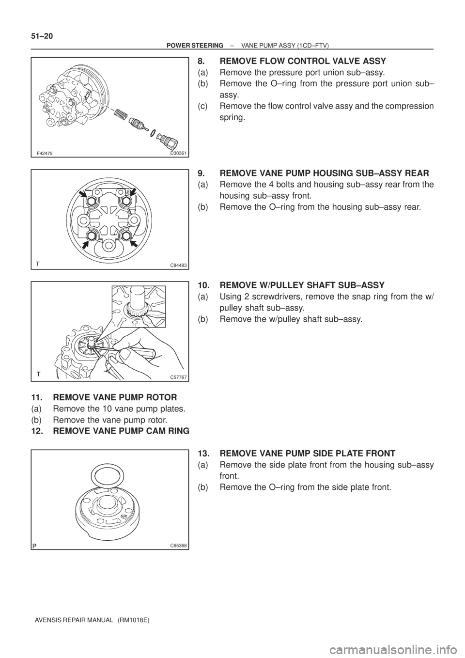
8. REMOVE FLOW CONTROL VALVE ASSY
(a) Remove the pressure port union sub±assy.
(b) Remove the O±ring from the pressure port union sub±
assy.
(c) Remove the flow control valve assy and the compression
spring.
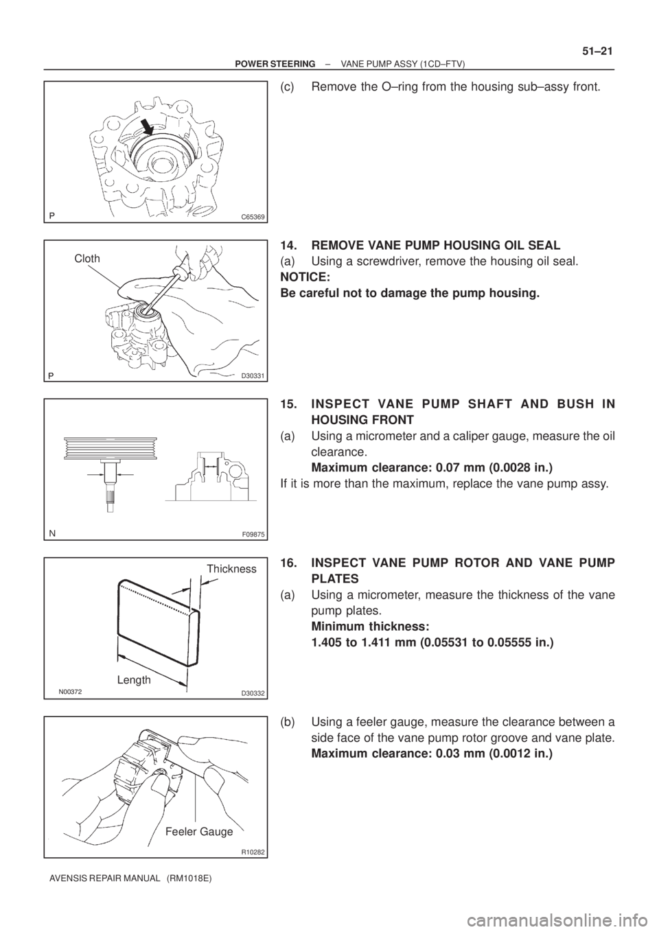
9. REMOVE VANE PUMP HOUSING SUB±ASSY REAR
(a) Remove the 4 bolts and housing sub±assy rear from the
housing sub±assy front.
(b) Remove the O±ring from the housing sub±assy rear.
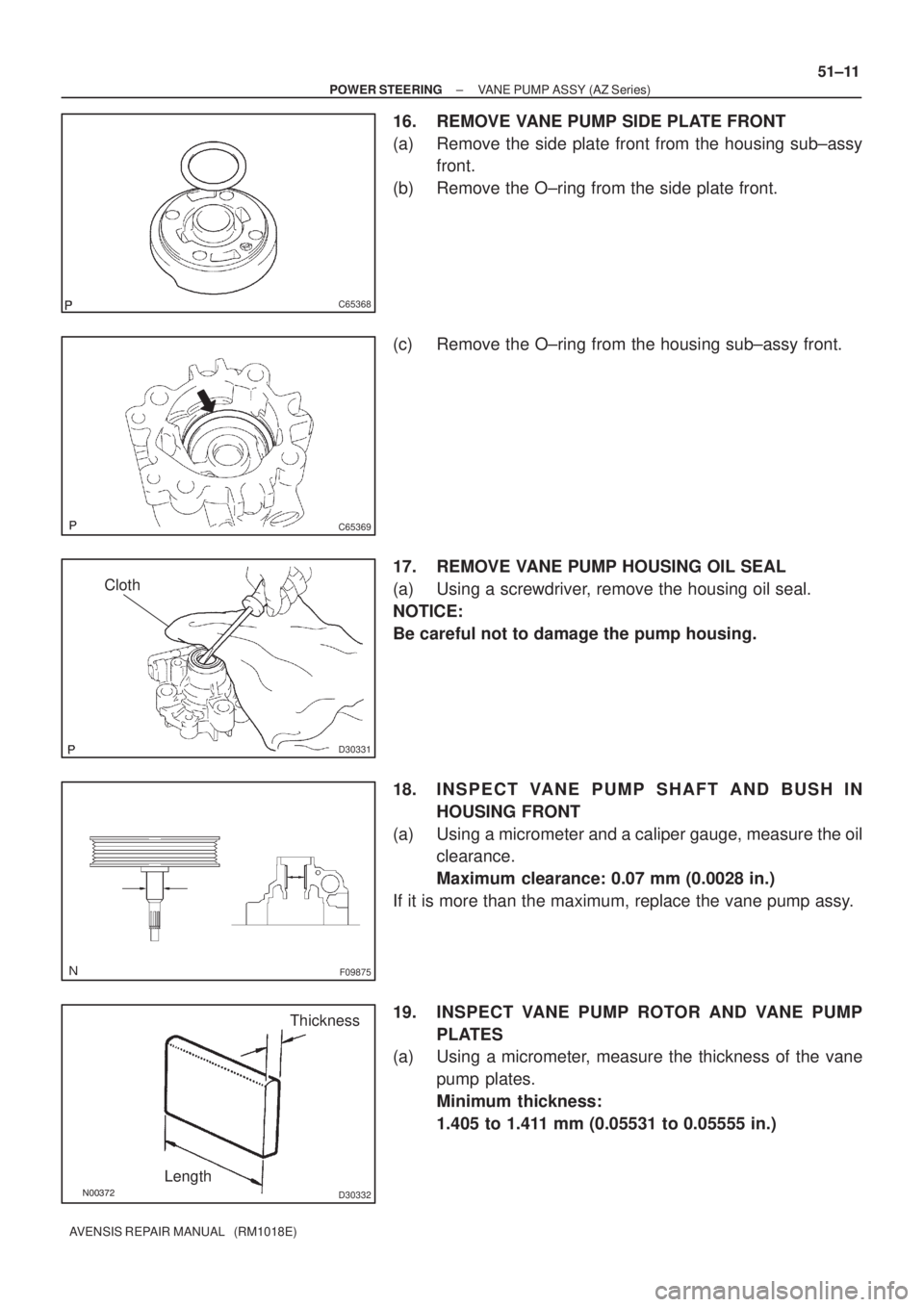
10. REMOVE W/PULLEY SHAFT SUB±ASSY
(a) Using 2 screwdrivers, remove the snap ring from the w/
pulley shaft sub±assy.
(b) Remove the w/pulley shaft sub±assy.
11. REMOVE VANE PUMP ROTOR
(a) Remove the 10 vane pump plates.
(b) Remove the vane pump rotor.
12. REMOVE VANE PUMP CAM RING
13. REMOVE VANE PUMP SIDE PLATE FRONT
(a) Remove the side plate front from the housing sub±assy
front.
(b) Remove the O±ring from the side plate front.
Page 2863 of 5135
C65369
D30331
Cloth
F09875
������D30332
LengthThickness
R10282
Feeler Gauge
± POWER STEERINGVANE PUMP ASSY (1CD±FTV)
51±21
AVENSIS REPAIR MANUAL (RM1018E)
(c) Remove the O±ring from the housing sub±assy front.
14. REMOVE VANE PUMP HOUSING OIL SEAL
(a) Using a screwdriver, remove the housing oil seal.
NOTICE:
Be careful not to damage the pump housing.
15. INSPECT VANE PUMP SHAFT AND BUSH IN
HOUSING FRONT
(a) Using a micrometer and a caliper gauge, measure the oil
clearance.
Maximum clearance: 0.07 mm (0.0028 in.)
If it is more than the maximum, replace the vane pump assy.
16. INSPECT VANE PUMP ROTOR AND VANE PUMP
PLATES
(a) Using a micrometer, measure the thickness of the vane
pump plates.
Minimum thickness:
1.405 to 1.411 mm (0.05531 to 0.05555 in.)
(b) Using a feeler gauge, measure the clearance between a
side face of the vane pump rotor groove and vane plate.
Maximum clearance: 0.03 mm (0.0012 in.)
Page 2867 of 5135

51±25
AVENSIS REPAIR MANUAL (RM1018E)
(b) Coat 10 vane pump plates with power steering")
������D30335
Inward
Outward
������D30336
C70126
F45776
Service Bolt
± POWER STEERINGVANE PUMP ASSY (1CD±FTV)
51±25
AVENSIS REPAIR MANUAL (RM1018E)
(b) Coat 10 vane pump plates with power steering fluid.
(c) Install the vane pump plates with the round end facing
outward.
25. INSTALL VANE PUMP SHAFT SNAP RING
(a) Using a screwdriver and a snap ring expander, install a
new snap ring to the w/pulley shaft sub±assy.
26. INSTALL VANE PUMP HOUSING SUB±ASSY REAR
(a) Coat a new O±ring with power steering fluid and install it
onto the housing sub±assy rear.
(b) Align the straight pin of the housing sub±assy rear with
the dents of the cam ring, side plate front and housing
sub±assy front, and install the vane pump housing sub±
assy rear with the 4 bolts.
Torque: 22 N�m (224 kgf�cm, 16 ft�lbf)
27. INSPECT PRELOAD
(a) Check that the pump rotates smoothly without abnormal
noise.
(b) Temporarily install the service bolt.
Recommended service bolt:
Thread diameter: 10 mm (0.39 in.)
Thread pitch: 1.25 mm (0.0492 in.)
Bolt length: 50 mm (1.97 in.)
(c) Using a torque wrench, check the pump rotating torque.
Rotating torque:
0.27 N�m (2.8 kgf�cm, 2.4 ft�lbf) or less
If the rotating torque is not as specified, check the housing oil
seal.
Page 2871 of 5135

AVENSIS REPAIR MANUAL (RM1018E)
9. REMOVE POWER STEERING SUCTION PORT UNION
(a) Remove the bolt and the suction port union.
(b")
F42475
C84483
C57767
51±10
± POWER STEERINGVANE PUMP ASSY (AZ Series)
AVENSIS REPAIR MANUAL (RM1018E)
9. REMOVE POWER STEERING SUCTION PORT UNION
(a) Remove the bolt and the suction port union.
(b) Remove the O±ring from the suction port union.
10. REMOVE FLOW CONTROL VALVE ASSY
(a) Remove the pressure port union sub±assy.
(b) Remove the O±ring from the pressure port union sub±
assy.
(c) Remove the flow control valve assy and the compression
spring.
11. REMOVE POWER STEERING OIL PRESSURE SWITCH
NOTICE:
If the oil pressure switch is dropped or damaged, replace it with a new one.
12. REMOVE VANE PUMP HOUSING SUB±ASSY REAR
(a) Remove the 4 bolts and housing sub±assy rear from the
housing sub±assy front.
(b) Remove the O±ring from the housing sub±assy rear.
13. REMOVE W/PULLEY SHAFT SUB±ASSY
(a) Using 2 screwdrivers, remove the snap ring from the w/
pulley shaft sub±assy.
(b) Remove the w/pulley shaft sub±assy.
14. REMOVE VANE PUMP ROTOR
(a) Remove the 10 vane pump plates.
(b) Remove the vane pump rotor.
15. REMOVE VANE PUMP CAM RING
Page 2872 of 5135
C65368
C65369
D30331
Cloth
F09875
������D30332
LengthThickness
± POWER STEERINGVANE PUMP ASSY (AZ Series)
51±11
AVENSIS REPAIR MANUAL (RM1018E)
16. REMOVE VANE PUMP SIDE PLATE FRONT
(a) Remove the side plate front from the housing sub±assy
front.
(b) Remove the O±ring from the side plate front.
(c) Remove the O±ring from the housing sub±assy front.
17. REMOVE VANE PUMP HOUSING OIL SEAL
(a) Using a screwdriver, remove the housing oil seal.
NOTICE:
Be careful not to damage the pump housing.
18. INSPECT VANE PUMP SHAFT AND BUSH IN
HOUSING FRONT
(a) Using a micrometer and a caliper gauge, measure the oil
clearance.
Maximum clearance: 0.07 mm (0.0028 in.)
If it is more than the maximum, replace the vane pump assy.
19. INSPECT VANE PUMP ROTOR AND VANE PUMP
PLATES
(a) Using a micrometer, measure the thickness of the vane
pump plates.
Minimum thickness:
1.405 to 1.411 mm (0.05531 to 0.05555 in.)
Page 2876 of 5135

51±15
AVENSIS REPAIR MANUAL (RM1018E)
(b) Coat 10 vane pump plates with power steerin")
������D30335
Inward
Outward
������D30336
C70126
C53369
Service Bolt
± POWER STEERINGVANE PUMP ASSY (AZ Series)
51±15
AVENSIS REPAIR MANUAL (RM1018E)
(b) Coat 10 vane pump plates with power steering fluid.
(c) Install the vane pump plates with the round end facing
outward.
28. INSTALL VANE PUMP SHAFT SNAP RING
(a) Using a screwdriver and a snap ring expander, install a
new snap ring to the w/pulley shaft sub±assy.
29. INSTALL VANE PUMP HOUSING SUB±ASSY REAR
(a) Coat a new O±ring with power steering fluid and install it
onto the housing sub±assy rear.
(b) Align the straight pin of the housing sub±assy rear with
the dents of the cam ring, side plate front and housing
sub±assy front, and install the vane pump housing sub±
assy rear with the 4 bolts.
Torque: 22 N�m (224 kgf�cm, 16 ft�lbf)
30. INSPECT PRELOAD
(a) Check that the pump rotates smoothly without abnormal
noise.
(b) Temporarily install the service bolt.
Recommended service bolt:
Thread diameter: 10 mm (0.39 in.)
Thread pitch: 1.25 mm (0.0492 in.)
Bolt length: 50 mm (1.97 in.)
(c) Using a torque wrench, check the pump rotating torque.
Rotating torque:
0.27 N�m (2.8 kgf�cm, 2.4 ft�lbf) or less
If the rotating torque is not as specified, check the housing oil
seal.
31. INSTALL POWER STEERING OIL PRESSURE SWITCH
(a) Coat a new O±ring with power steering fluid and install it to the oil pressure switch.
(b) Install the oil pressure switch onto the vane pump assy.
Torque: 21 N�m (214 kgf�cm, 15 ft�lbf)
Page 3458 of 5135
022KC±01
± PREPARATIONSTARTING & CHARGING
02±5
1AZ±FSE ENGINE REPAIR MANUAL (RM1019E)
STARTING & CHARGING
PREPARATION
SST
09285±76010Injection Pump Camshaft Bearing
Cone ReplacerGENERATOR ASSY
Recomended Tools
09041±00020Torx Driver T25STARTER ASSY
09904±00010Expander SetSTARTER ASSY
(09904±00050)No. 4 ClawSTARTER ASSY
Equipment
Dial indicator
Ohmmeter
Torque wrench
Slide calipers
V±block
Page 3479 of 5135

5. REMOVE PISTON RING SET
(a) Using a piston ring expander, remove the 2 com")
A14289
A13861
A01178
A01179
A13851
± ENGINE MECHANICALCYLINDER BLOCK ASSY
14±55
1AZ±FSE ENGINE REPAIR MANUAL (RM1019E)
5. REMOVE PISTON RING SET
(a) Using a piston ring expander, remove the 2 compression
rings.
(b) Remove the 2 side rails and oil ring by hand.
6. REMOVE PISTON
(a) Using a small screwdriver, pry out the 2 snap rings.
(b) Gradually heat the piston to 80 to 90 �C (176 to 194 �F).
(c) Using a plastic±faced hammer and brass bar, lightly tap
out the piston pin and remove the connecting rod.
HINT:
�The piston and pin are a matched set.
�Store the pistons, pins, rings, connecting rods and bear-
ings in correct order so that they can be returned to the
original locations when re±assembling.
7. INSPECT CRANKSHAFT THRUST CLEARANCE
(a) Using a dial indicator, measure the thrust clearance while
prying the crankshaft back and forth with a screwdriver.
Standard thrust clearance:
0.040 to 0.240 mm (0.0016 to 0.0094 in.)
Maximum thrust clearance: 0.30 mm (0.0118 in.)
(b) If the thrust clearance is greater than maximum, replace
the thrust washers as a set.
Thrust washer thickness:
1.930 to 1.980 mm (0.0760 to 0.0780 in.)

STARTING & CHARGING
PREPARATION
SST
09285±76010Injection Pump Camshaft Bearing
Cone ReplacerGENERATOR ASSY")