Page 4624 of 5135

14−176−
ENGINE MECHANICAL CYLINDER HEAD GASKET (1CD −FTV)(From
September, 2003)
AVENSIS Supplement (RM1045E)
122. SET NO. 1 CYLINDER TO TDC/COMPRESSION (See page 14 −138)
SST 09960 −10010 (09962 −01000, 09963 −01000)
123. INSTALL TIMING BELT (See page 14 −138)
124. CHECK VALVE TIMING (See page 14 −138)
125. INSTALL TIMING CHAIN COVER PLATE (See page 14 −138)
126. INSTALL TRANSVERSE ENGINE ENGINE MOUNTING BRACKET (See page 14 −138)
127. INSTALL TIMING BELT GUIDE (See page 14 −138)
128. INSTALL TIMING BELT NO.1 COVER (See page 14 −138)
129. INSTALL TIMING BELT NO.2 COVER (See page 14 −138)
130. INSTALL IDLER PULLEY SUB −ASSY (See page 14 −138)
131. INSTALL CRANKSHAFT PULLEY (See page 14 −138)
SST 09213 −54015 (09213 −70020), 09330 −00021
132. INSTALL ENGINE MOUNTING INSULATOR SUB −ASSY RH (See page 14 −138)
133. INSTALL POWER STEERING IDLE PULLEY BRACKET (See page 14 −108)
134. ADJUST V (COOLER COMPRESSOR TO CRANKSHAFT PULLEY) BELT NO.1
(See Pub. No. RM1018E on page 14 −269)
135. INSTALL INJECTOR DRIVER (See page 14 −108 )
136. INSTALL AIR TUBE NO.1 (See page 14 −108)
137. INSTALL AIR TUBE NO.2 (See page 14 −108)
138. INSTALL DIFFERENTIAL PRESSURE SENSOR ASSY (See page 14 −108)
139. INSTALL BATTERY (See page 14 −108)
140. INSTALL AIR CLEANER ASSY (See page 14 −108)
141. INSTALL VACUUM RESERVOIR SUB −ASSY (See page 14 −108)
142. INSTALL ENGINE COVER SUB −ASSY NO.1 (See page 14 −90)
143. INSTALL FRONT WHEEL RH Torque: 103 N �m (1,050 kgf �cm, 76 ft �lbf)
144. ADD ENGINE OIL (See Pub. No. RM1018E on page 17 −30)
145. ADD ENGINE COOLANT (See page 16 −19)
146. CHECK FOR FUEL LEAKS (See page 11 −46)
147. CHECK FOR ENGINE OIL LEAKS
148. CHECK FOR ENGINE COOLANT LEAKS (See page 16 −15)
149. CHECK FOR EXHAUST GAS LEAKS
Page 4625 of 5135

141NK−01
SSTA61187
−
ENGINE MECHANICAL CAMSHAFT (1CD−FTV)(From September, 2003)
14 −151
AVENSIS Supplement (RM1045E)
REPLACEMENT
1. REMOVE FRONT WHEEL RH
2. REMOVE ENGINE UNDER COVER LH
3. REMOVE ENGINE UNDER COVER SUB −ASSY NO.1
4. REMOVE ENGINE UNDER COVER RH
5. REMOVE RADIATOR SUPPORT OPENING COVER
6. REMOVE ENGINE ROOM COVER SIDE
7. REMOVE ENGINE COVER SUB −ASSY NO.1 (See page 14 −90)
8. REMOVE AIR CLEANER ASSY (See page 14 −108)
9. REMOVE BATTERY
10. REMOVE VACUUM RESERVOIR SUB −ASSY (See page 14 −108)
11. REMOVE AIR TUBE NO.1 (See page 14 −108)
12. REMOVE INJECTOR DRIVER (See page 14 −108)
13. REMOVE V (COOLER COMPRESSOR TO CRANKSHAFT PULLEY) BELT NO.1 (See Pub. No. RM1018E on page 14 −269)
14. REMOVE GENERATOR V BELT (See Pub. No. RM1018E on page 14 −269)
15. SEPARATE POWER STEERING IDLE PULLEY BRACKET (See page 14 −138)
16. DISCONNECT ENGINE WIRE (See page 14 −138)
17. DISCONNECT VACUUM HOSE (See page 14 −108)
18. REMOVE ENGINE MOUNTING INSULATOR SUB −ASSY RH (See page 14 −138)
19. REMOVE CRANKSHAFT PULLEY (See page 14 −138)
SST 09213 −54015 (09213 −70020), 09330 −00021, 09950 −50013 (09951 −05010, 09952 −05010,
09953 −05020, 09954 −05031)
20. REMOVE IDLER PULLEY SUB −ASSY (See page 14 −138)
21. REMOVE TIMING BELT NO.2 COVER (See page 14 −138)
22. REMOVE TIMING BELT NO.1 COVER (See page 14 −138)
23. REMOVE TIMING BELT GUIDE
24. REMOVE TRANSVERSE ENGINE ENGINE MOUNTING BRACKET (See page 14 −138)
25. SET NO. 1 CYLINDER TO TDC/COMPRESSION (See page 14 −138)
26. REMOVE TIMING CHAIN COVER PLATE (See page 14 −138)
27. REMOVE TIMING BELT (See page 14 −138)
28. REMOVE CAMSHAFT POSITION SENSOR (See page 14 −108)
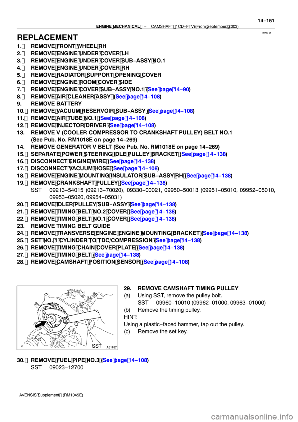
29. REMOVE CAMSHAFT TIMING PULLEY
(a) Using SST, remove the pulley bolt. SST 09960 −10010 (09962 −01000, 09963 −01000)
(b) Remove the timing pulley.
HINT:
Using a plastic −faced hammer, tap out the pulley.
(c) Remove the set key.
30. REMOVE FUEL PIPE NO.3 (See page 14 −108)
SST 09023 −12700
Page 4630 of 5135

A85428
Seal Width
2to4mm
(0.08 to 0.16 in.)Seal Packing
A62592
SST
A85760
90_
14
−156
−
ENGINE MECHANICAL CAMSHAFT (1CD−FTV)(From September, 2003)
AVENSIS Supplement (RM1045E)
(b) Apply seal packing to the oil seal retainer as shown in the illustration.
Seal packing: Part No. 08826 −00080 or equivalent
(1) Install a nozzle of which opening is cut to 2 to 4 mm
(0.08 to 0.16 in.).
(2) The parts must be set within 3 minutes and must be
assembled within 15 minutes after applying seal
packing.
(3) Immediately remove the nozzle from the tube, then reinstall the cap.
(c) Install the oil seal retainer with the 4 bolts. Tighten the 4 bolts uniformly in several steps.
Torque: 9.8 N �m (100 kgf �cm, 7.2 ft �lbf)
52. INSTALL CAMSHAFT TIMING PULLEY
(a) Install the pulley set key to the groove of the camshaft.
(b) Align the keyway of the timing pulley with the key located on the camshaft, then slide the pulley into place.
(c) Using SST, install the pulley bolt. SST 09960 −10010 (09962 −01000, 09963 −01000)
Torque: 88 N �m (899 kgf �cm, 65 ft �lbf)
53. INSTALL CAMSHAFT POSITION SENSOR (See page 14 −108)
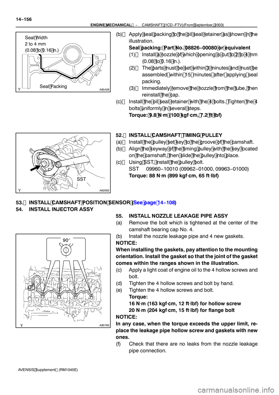
54. INSTALL INJECTOR ASSY 55. INSTALL NOZZLE LEAKAGE PIPE ASSY
(a) Remove the bolt which is tightened at the center of thecamshaft bearing cap No. 4.
(b) Install the nozzle leakage pipe and 4 new gaskets.
NOTICE:
When installing the gaskets, pay attention to the mounting
orientation. Install the gasket so that the joint of the gasket
comes within the ranges shown in the illustration.
(c) Apply a light coat of engine oil to the 4 hollow screws and bolt.
(d) Tighten the 4 hollow screws and bolt by hand.
(e) Tighten the 4 hollow screws and bolt. Torque:
16 N�m (163 kgf �cm, 12 ft �lbf) for hollow screw
20 N �m (204 kgf �cm, 15 ft �lbf) for flange bolt
NOTICE:
In any case, when the torque exceeds the upper limit, re-
place the leakage pipe hollow screw and gaskets with new
ones.
(f) Check that there are no leaks from the nozzle leakage pipe connection.
Page 4635 of 5135
A85616
Injector Driver
5.5 (56, 49 in.·lbf)
52 (530, 38)
Engine Mounting Insulator Sub−assy RH
52 (530, 38)x3
8.3 (85, 73 in.·lbf)
Vacuum Reservoir Sub−assy
Vacuum Warning
Switch Connector
Vacuum Hose Assy
52 (530, 38)
Union to Connector
Tube Hose
Turbo Pressure
Sensor Connector
VRV Connector
25 (255, 18)
Air Tube No. 1
N·m (kgf·cm, ft·lbf)
: Specified torque
25 (255, 18)
25 (255, 18)
6.0 (61, 53 in.·lbf)
6.0 (61, 53 in.·lbf)
Battery
Battery Tray
Air Hose No. 2
5.0 (51, 44 in.�lbf)
3.0 to 4.0 (31 to 41, 27 to 35 in.�lbf)
− ENGINE MECHANICALCAMSHAFT (1CD−FTV)(From September, 2003)
14−147
AVENSIS Supplement (RM1045E)
Page 4638 of 5135
A85618
N·m (kgf·cm, ft·lbf)
: Specified torque
zNon−reusable part
21 (214, 15)
Vacuum Pump Assy
zO−ring
20 (204, 15)
20 (204, 15)
Camshaft
No. 2 Camshaft
Set Key
Camshaft Timing Pulley
88 (899, 65)
Camshaft Carrier
zOil Seal
8.8 (90, 78 in.�lbf)Camshaft Oil Seal
Retainer
9.8 (100, 7.2)
Camshaft Position
Sensor
9.8 (100, 7.2)
Camshaft Bearing Cap
14−150
− ENGINE MECHANICALCAMSHAFT (1CD−FTV)(From September, 2003)
AVENSIS Supplement (RM1045E)
Page 4639 of 5135
141NI−01
A61175
A84394
A61184
14 −138
−
ENGINE MECHANICAL TIMING BELT (1CD−FTV)(From September, 2003)
AVENSIS Supplement (RM1045E)
REPLACEMENT
1. REMOVE FRONT WHEEL RH
2. REMOVE ENGINE UNDER COVER SUB −ASSY NO.1
3. REMOVE ENGINE UNDER COVER RH
4. REMOVE RADIATOR SUPPORT OPENING COVER
5. REMOVE ENGINE ROOM COVER SIDE
6. REMOVE ENGINE COVER SUB −ASSY NO.1 (See page 14 −90)
7. REMOVE INJECTOR DRIVER (See page 14 −108)
8. REMOVE V (COOLER COMPRESSOR TO CRANKSHAFT PULLEY) BELT NO.1 (See Pub. No. RM1018E on page 14 −269)
9. REMOVE GENERATOR V BELT (See Pub. No. RM1018E on page 14 −269)
10. SEPARATE PO W ER STEERI NG I DLE PULLEY BRACKET
(a) Remove the 3 bolts and power steering idle pulley brack- et.
11. DISCONNECT ENGINE WIRE
(a) Disconnect the 2 exhaust gas temperature sensor con- nectors.
12. DISCONNECT VACUUM HOSE (See page 14 −108)
13. REMOVE ENGINE MOUNTING INSULATOR SUB−ASSY RH
(a) Place a wooden block on a jack underneath the engine.
Page 4651 of 5135
A85929
(g)
(f)
(g)
A84394
A84395
A84396
(a)
(b)
A93840
Air Hose No. 2
To
Turbocharger (b)
(b)(c)
(c)
(c) 14−11 0
− ENGINE MECHANICALPARTIAL ENGINE ASSY (1CD−FTV)(From September,
2003)
AVENSIS Supplement (RM1045E)
(f) Remove the bolt and engine room relay block No. 3.
(g) Disconnect the 2 connectors.
(h) Disconnect the wire harness from the fuel filter support.
(i) Disconnect the 2 exhaust gas temperature sensor con-
nectors.
27. DISCONNECT VACUUM HOSE
(a) Disconnect the 2 vacuum hoses.
28. REMOVE DIFFERENTIAL PRESSURE SENSOR ASSY
(a) Disconnect the connector.
(b) Remove the bolt and differential pressure sensor.
29. REMOVE AIR TUBE NO.1
(a) Disconnect the vacuum hoses and connectors.
(b) Loosen the 2 hose clamps.
(c) Remove the 2 bolts and nut, then detach the air tube No.
1.
Page 4653 of 5135
A79184
A85928
A61177
A59793
A59792
14−11 2− ENGINE MECHANICALPARTIAL ENGINE ASSY (1CD−FTV)(From September,
2003)
AVENSIS Supplement (RM1045E)
46. REMOVE ENGINE ASSEMBLY WITH TRANSAXLE
(a) Disconnect the height control sensor connector (with dis-
charge head lamp).
(b) Set the engine lifter.
(c) Remove the 3 bolts, 3 nuts and engine mounting insulator
sub−assembly RH.
(d) Remove the through bolt and nut, then detach the engine
mounting insulator LH from the vehicle.
(e) Remove the 8 bolts and front suspension member brace
rear RH and LH.
(f) Remove the 2 bolts and 2 nuts.
(g) Carefully remove the engine together with the transaxle
from the vehicle.