Page 4554 of 5135
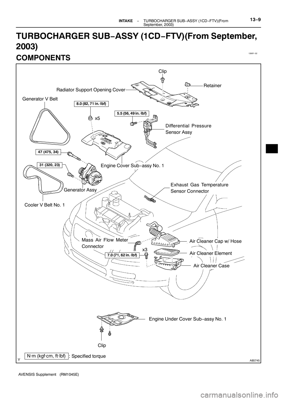
1306Y−02
A85745
8.0 (82, 71 in.�lbf)
Engine Cover Sub−assy No. 1 Radiator Support Opening Cover
N·m (kgf·cm, ft·lbf)
: Specified torque
7.0 (71, 62 in.�lbf)
Air Cleaner Cap w/ Hose
Air Cleaner Element
Air Cleaner Case
Engine Under Cover Sub−assy No. 1 Clip
Retainer
Clip
x5
x3 Cooler V Belt No. 1 Generator V Belt
Generator Assy
47 (475, 34)
31 (320, 23)
Differential Pressure
Sensor Assy
Exhaust Gas Temperature
Sensor Connector
5.5 (56, 49 in.�lbf)
Mass Air Flow Meter
Connector
− INTAKETURBOCHARGER SUB−ASSY (1CD−FTV)(From
September, 2003)13−9
AVENSIS Supplement (RM1045E)
TURBOCHARGER SUB−ASSY (1CD−FTV)(From September,
2003)
COMPONENTS
Page 4556 of 5135
A85747
N·m (kgf·cm, ft·lbf)
: Specified torque
zNon−reusable partzGasket
zGasket zGasket
20 (204, 15)
20 (204, 15)
20 (204, 15)
12 (122, 8.9)
60 (612, 44)
13 (135, 9.8)
36 (367, 27)
61 (622, 45)
56 (571, 41)
25 (255, 18)
Turbo Insulator No. 1
Exhaust Manifold Heat Insulator No. 2
Turbocharger Stay
Turbocharger Sub−assy
Turbo Oil Inlet Pipe
Sub−assy
Manifold Stay Manifold Stay No. 2
Exhaust Manifold
Converter Sub−assy Turbo Insulator No. 2
Turbo Water Pipe
Sub−assy No. 1
13 (135, 9.8)
56 (571, 41)
Turbo Water
Hose No. 2
Turbo Water
Hose No. 1
zGasket
12 (122, 8.9)
z
EGR Pipe Insulator
12 (122, 8.9)
x3x3
x2
x4
25 (255, 18)
Exhaust Gas Temperature
Sensor
Vacuum Transmitting
Pipe Sub−assy No. 2
30 (306, 22)
Vacuum Transmitting
Pipe Sub−assy No. 1
30 (306, 22)
x3
z
− INTAKETURBOCHARGER SUB−ASSY (1CD−FTV)(From
September, 2003)13−11
AVENSIS Supplement (RM1045E)
Page 4557 of 5135
(From
September, 2003)
AVENSIS Supplement (RM1045E)
ON−VEHICLE INSPECTION
1. INSPECT INTAKE AIR SYSTEM
(a) Check for")
1302Z−04
A77123
SST
A60595E2 VC
13−6− INTAKETURBO CHARGER SYSTEM (1CD−FTV)(From
September, 2003)
AVENSIS Supplement (RM1045E)
ON−VEHICLE INSPECTION
1. INSPECT INTAKE AIR SYSTEM
(a) Check for leakage or clogging between the air cleaner housing and turbocharger inlet and between
the turbocharger outlet and cylinder head.
ConditionOperation
Clogged air cleanerClean or replace the element
Collapsed or deformed hosesRepair or replace
Leakage from connectionsCheck each connection and repair
Cracks in componentsCheck and replace
2. INSPECT EXHAUST SYSTEM
(a) Check for leakage or clogging between the cylinder head and turbocharger inlet and between the
turbocharger outlet and exhaust pipe.
ConditionOperation
Deformed componentsRepair or replace
Foreign material in passagesRemove
Leakage from componentsRepair or replace
Cracks in componentsCheck and replace
3. CHECK TURBOCHARGING PRESSURE
(a) Warm up the engine.
(b) Using a 3−way connector, connect SST (turbocharger
pressure gauge) to the hose leading to the intake air con-
nector.
SST 09992−00242
(c) While depressing the clutch pedal, press the accelerator
pedal down fully. Measure the turbocharging pressure at
the maximum speed (5,100 to 5,250 rpm).
Standard pressure:
15 to 45 kPa (0.15 to 0.46 kgf/cm
2, 2.2 to 6.5 psi)
If the pressure is less than specification, check both the intake
air and exhaust systems for leakage.
If there is no leakage, check if the actuator hose has discon-
nected. If not, check the turbocharger.
If the pressure is greater than the specification, check if the ac-
tuator hose has disconnected or cracked. If not, check the
turbocharger.
4. INSPECT TURBO PRESSURE SENSOR
(a) Inspect the power source voltage.
(1) Disconnect the turbo pressure sensor connector.
(2) Turn the ignition switch to ON.
(3) Using a voltmeter, measure the voltage between
connector terminals 3 (VC) and 1 (E2) of the wire
harness side.
Voltage: 4.5 to 5.5 V
If the result is not as specified, check the wiring and ECM.
Page 4558 of 5135

E2 (−) ECM Connector
Vacuum SST
E13 E12
A77125
SST
Pressure
− INTAKETURBO CHARGER SYSTEM (1CD−FTV)(From
September, 2003)13−7
AVENSIS Supplement (RM1045E)
(4) Turn the ignition s")
A87890
PIM (+)
E2 (−) ECM Connector
Vacuum SST
E13 E12
A77125
SST
Pressure
− INTAKETURBO CHARGER SYSTEM (1CD−FTV)(From
September, 2003)13−7
AVENSIS Supplement (RM1045E)
(4) Turn the ignition switch to OFF.
(5) Reconnect the turbo pressure sensor connector.
(b) Inspect the supply power.
(1) Turn the ignition switch to ON.
(2) Disconnect the vacuum hose from the turbo pres-
sure sensor.
(3) Connect a voltmeter to terminals E12−28 (PIM) and
E13−28 (E2) of the ECM, then measure the output
voltage under atmospheric pressure.
(4) Apply vacuum to the turbo pressure sensor in 13.3
kPa (100 mmHg, 3.94 in.Hg) to 66.7 kPa (500
mmHg, 19.69 in.Hg).
(5) Measure the voltage decrease from step (3).
Voltage drop:
Apply Vacuum
[kPa (mmHg, in.Hg)]Voltage Decrease
[V]
13.3 (100, 3.94)0.1 to 0.3
26.7 (200, 7.87)0.3 to 0.5
40.0 (300, 11.81)0.5 to 0.7
57.3 (400, 15.75)0.7 to 0.9
66.7 (500, 19.69)0.9 to 1.0
(6) Using SST (a turbocharger pressure gauge), apply
pressure to the turbo pressure sensor in 19.6 kPa
(0.20 kgf/cm
2, 2.84 psi) to 98.0 kPa (1.00 kgf/cm2,
14.2 psi).
SST 09992−00242
(7) Measure the voltage increase from step (3).
Voltage up:
Applied Pressure
[kPa (kgf/cm2, psi)]
Voltage Increase
[V]
19.6 (0.20, 2.84)0.1 to 0.4
39.2 (0.40, 5.69)0.4 to 0.7
58.8 (0.60, 8.53)0.7 to 1.0
78.5 (0.80, 11.4)1.0 to 1.3
98.0 (1.00, 14.2)1.3 to 1.6
If the result is not as specified, check the wiring and ECM.
Page 4561 of 5135
120DD−01
32 1
A85764
EGLS
E2VC
− EMISSION CONTROLEGR SYSTEM (1CD−FTV)(From September, 2003)
12−9
AVENSIS Supplement (RM1045E)
INSPECTION
1. INSPECT EGR VALVE POSITION SENSOR
(a) Inspect the resistance.
(1) Using an ohmmeter, measure the resistance be-
tween terminals 1 (VC) and 2 (E2).
Resistance: 4.0 to 6.0 k�at 20_C (68_F)
If the result is not as specified, replace the EGR valve position
sensor.
2. INSPECT EGR VALVE ASSY
(a) Inspect the resistance.
(1) Using an ohmmeter, measure the resistance between the terminals.
Resistance: 6.5 to 7.5�at 20_C (68_F)
If the result is not as specified, replace the EGR valve assembly.
Page 4562 of 5135
(From
September, 2003)12 −7
AVENSIS Supp")
120DC−01
A86428
1
2
E2
THG
A87894
+B HT
AF+
AF
− 2
3
4 1
A92423
W/HID:
HT
AF+
+B
AF − 1
2
3
4
−
EMISSION CONTROL EMISSION CONTROL SYSTEM (1CD −FTV)(From
September, 2003)12 −7
AVENSIS Supplement (RM1045E)
INSPECTION
1. I NSPECT EXHAUST F UEL ADDI TI O N I NJECTO R
ASSY
(a) Inspect the resistance. (1) Using an ohmmeter, measure the resistance be- tween the terminals.
Resistance: 11.6 to 12.4 � at 20 _C (68 _F)
If the result is not as specified, replace the exhaust fuel addition
injector assembly (see page 14 −166).
2. INSPECT EXHAUST GAS TEMPERATURE SENSOR
(a) Inspect the resistance. (1) Using an ohmmeter, measure the resistance be-
tween the terminals.
Resistance: 242 k � at 20 _C (68 _F)
If the result is not as specified, replace the exhaust gas temper-
ature sensor (see page 14 −108).
3. INSPECT AIR −FUEL RATIO SENSOR
(a) Inspect the resistance.
(1) Using an ohmmeter, measure the resistance be- tween the terminals.
Resistance:
Tester ConnectionResistance
1 (HT) − 2 (+B)0.8 to 1.4 � at 20 _ C (68 _ F)
1 (HT) − 4 (AF −)10 k � or higher
If the result is not as specified, replace the air −fuel ratio sensor
(see page 15 −6) .
Page 4572 of 5135
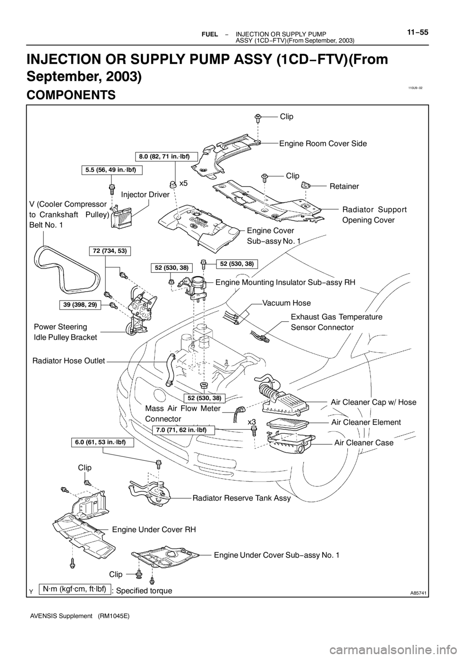
110U9−02
A85741
Air Cleaner Cap w/ Hose
Air Cleaner Element
Air Cleaner Case
7.0 (71, 62 in.�lbf)
N·m (kgf·cm, ft·lbf)
: Specified torque
Radiator Hose Outlet
Clip
Engine Room Cover Side
Clip
Retainer
Radiator Support
Opening Cover
8.0 (82, 71 in.�lbf)
5.5 (56, 49 in.�lbf)
V (Cooler Compressor
to Crankshaft Pulley)
Belt No. 1
Injector Driver
72 (734, 53)
52 (530, 38)52 (530, 38)
Engine Cover
Sub−assy No. 1
Engine Mounting Insulator Sub−assy RH
39 (398, 29)
Power Steering
Idle Pulley Bracket
52 (530, 38)
Clip
Engine Under Cover RH
Engine Under Cover Sub−assy No. 1
Clip
Radiator Reserve Tank Assy
6.0 (61, 53 in.�lbf)
x5
x3
Exhaust Gas Temperature
Sensor Connector
Vacuum Hose
Mass Air Flow Meter
Connector
− FUELINJECTION OR SUPPLY PUMP
ASSY (1CD−FTV)(From September, 2003)11−55
AVENSIS Supplement (RM1045E)
INJECTION OR SUPPLY PUMP ASSY (1CD−FTV)(From
September, 2003)
COMPONENTS
Page 4590 of 5135

(b)
Pull Out
A88252
(a)
(b)
(c)
(d)
A77920
RHD:
LHD:
−
FUEL FUEL INJECTOR ASSY (2AZ −FSE)
11 −13
AVENSIS Supplement (RM1045E)
REPLACEMENT
1. DISCHARGE FUEL SYSTEM PRESSURE")
1111 4−01
A88253
(a)
(b)
Pull Out
A88252
(a)
(b)
(c)
(d)
A77920
RHD:
LHD:
−
FUEL FUEL INJECTOR ASSY (2AZ −FSE)
11 −13
AVENSIS Supplement (RM1045E)
REPLACEMENT
1. DISCHARGE FUEL SYSTEM PRESSURE (See page 11 −1)
2. REMOVE RADIATOR SUPPORT OPENING COVER (See page 10 −8)
3. REMOVE ENGINE ROOM COVER SIDE (See page 10 −8)
4. DISCONNECT ENGINE WIRE NO.3 (BATTERY NEGATIVE TERMINAL)
5. DRAIN ENGINE COOLANT (See page 16 −7)
6. REMOVE ENGINE COVER SUB −ASSY NO.1 (See page 10 −8)
7. REMOVE AIR CLEANER CAP SUB −ASSY (See page 10 −8)
8. REMOVE THROTTLE BODY ASSY (See page 10 −8)
9. REMOVE FUEL TUBE SUB −ASSY (See page 11 −24)
SST 09617 −24011
10. REMOVE FUEL HOSE (See page 11 −24)
11. REMOVE FUEL PIPE SUB −ASSY NO.1 (See page 11 −24)
SST 09023 −12900
12. REMOVE FUEL PUMP ASSY (See page 11 −24)
13. REMOVE CHARCOAL CANISTER ASSY
(a) Disconnect the fuel hose from the charcoal canister hose.
(b) Disconnect the charcoal canister outlet hose No. 1 from the charcoal canister.
(c) Pull out the charcoal canister from the charcoal canister base bracket.
14. REMOVE VACUUM SENSOR ASSY (LHD STEERING POSITION TYPE)
(a) Remove the wiring harness clamp.
(b) Disconnect the vacuum sensor connector.
(c) Disconnect the vacuum hose from the vacuum sensor.
(d) Remove the bolt, then remove the vacuum sensor.
15. REMOVE INTAKE MANIFOLD
(a) Disconnect the union to connector tube hose from the
brake booster.

: Specified torque
zNon−reusable partzGasket
zGasket zGasket
20 (204, 15)
20 (204, 15)
20 (204, 15)
12 (122, 8.9)
60 (612, 44)
13 (135, 9.8)
36 (367, 27)
61 (622, 45)")
(From September, 2003)
12−9
AVENSIS Supplement (RM1045E)
INSPECTION
1. INSPECT EGR VALVE POSITION SENSOR
(a) Inspect the re")