Page 4449 of 5135

A85350
E18
Front View
Wire Harness Side:
EGR valve position Sensor Connector
12 3
VC E2 EGLS
A81087
E12
ECM Connector
EGLS
A85350
E18
Front View
Wire Harness Side:
EGR valve position Sensor Connector
12 3
VC E2 EGLS
A81087
E12
ECM Connector
EGLS
−
DIAGNOSTICS ECD SYSTEM (1CD−FTV)(From September, 2003)
05 −40 1
AVENSIS Supplement (RM1045E)
3 CHECK HARNESS AND CONNECTOR(EGR VALVE POSITION SENSOR − ECM)
(a) Disconnect the E18 EGR valve position sensor connec-
tor.
(b) Disconnect the E12 ECM connector.
(c) Check the resistance between the wire harness side con-
nectors.
Standard (Check for open):
Tester ConnectionSpecified Condition
EGLS (E18 −3) − EGLS (E12 −33)Below 1 �E2 (E18 −2) − E2 (E13 −28)Below 1 �
Standard (Check for short):
Tester ConnectionSpecified Condition
EGLS (E18 −3) or EGLS (E12 −33) − Body ground10 k � or higher
(d) Reconnect the EGR valve position sensor connector.
(e) Reconnect the ECM connector.
NG REPAIR OR REPLACE HARNESS OR CONNECTOR
OK
REPLACE ECM (See page 10− 29)
4 CHECK HARNESS AND CONNECTOR(EGR VALVE POSITION SENSOR −ECM)
(a) Disconnect the E18 EGR valve position sensor connec-
tor.
(b) Disconnect the E12 ECM connector.
(c) Check the resistance between the wire harness side con- nectors.
Standard (Check for open):
Tester ConnectionSpecified Condition
EGLS (E18 −3) −EGLS (E12 −33)Below1�E2 (E18 −2) −E2 (E13 −28)Below 1 �
Standard (Check for short):
Tester ConnectionSpecified Condition
EGLS (E18 −3) or EGLS (E12 −33) −Body ground10 k �or higher
(d) Reconnect the EGR valve position sensor connector.
(e) Reconnect the ECM connector.
Page 4451 of 5135
− DIAGNOSTICSECD SYSTEM (1CD−FTV)(From September, 2003)
05−393
AVENSIS Supplement (RM1045E)
DTC P0400 EXHAUST GAS RECIRCULATION FLOW
CIRCUIT DESCRIPTION
The EGR system recirculates exhaust gases, and which is controlled to the proper volume to be suited every
driving condition. The recirculated gas mingles with the intake air, therefore the EGR system can slow down
engine combustion and let the combustion temperature down. This helps reduce a NOx emission.
In order to increase a circulatory efficiency, the ECM adjusts the lift amount of the EGR valve and intake
shutter valve (throttle valve).
DTC No.DTC Detection ConditionTrouble Area
P0400Target and actual positions of the EGR valve is different
(1trip detection logic)
SEGR valve stuck
SEGR valve does not move smoothly
SOpen or short in EGR circuit
SOpen or short in EGR valve position sensor circuit
SEGR valve position sensor
SECM
05I7N−01
Page 4452 of 5135
A93020
Malfunction Detection:
Abnormal
(Does not move smoothly) EGR Valve Opening
Position (Target)
Normal
Open
EGR Valve Position Sensor
Opening Position (Actual)Close
Abnormal
(Stuck)
Time
Threshold
Malfunction CounterDetect P0400Open
Close 05−394
− DIAGNOSTICSECD SYSTEM (1CD−FTV)(From September, 2003)
AVENSIS Supplement (RM1045E)
MONITOR DESCRIPTION
When the target and actual positions of the EGR valve is different, the ECM interprets this as malfunction
of the EGR valve and illuminates the CHK ENG.
Page 4458 of 5135
(From September, 2003)
05−387
AVENSIS Supplement (RM1045E)DTC No.
DTC Detection ConditionTrouble Area
P0380
When the glow plug is turned from ON to OFF, or vice")
− DIAGNOSTICSECD SYSTEM (1CD−FTV)(From September, 2003)
05−387
AVENSIS Supplement (RM1045E)DTC No.
DTC Detection ConditionTrouble Area
P0380
When the glow plug is turned from ON to OFF, or vice versa,
conditions (a) and (b) are satisfied:
(2 trip detection logic)
(a) Battery voltage does not change
(b) Duty signal from terminal M of the generator (alternator)
does not changeSOpen or short in glow plug circuit
SGlow fuse
SGlow plug relay
SGlow plug
SECM
MONITOR DESCRIPTION
When starting a cold engine, the ECM supplies current to the glow plug for a certain period of time. As supply-
ing the current to the glow plug is terminated, the large current is suddenly cut off, therefore the battery volt-
age then varies and also the output (duty ratio) from terminal M of the generator (alternator) varies. If these
variations are not occurred when the glow plug is turned from ON to OFF, or vice versa, the ECM judges the
current has not been supplied to the glow plug, and interprets this as open malfunction of the glow plug or
glow plug circuit.
MONITOR STRATEGY
Required SensorsGlow plug circuit
Frequency of operationTwice per driving cycle
Duration3 minutes
CHK ENG Operation2 driving cycles
TYPICAL ENABLING CONDITIONS
ItemSpecificationItemMinimumMaximum
Battery voltage11 V−
Engine speed700 rpm2,000 rpm
Engine coolant temperature−40_C (104_F)
Engine speed is stable−
Time after engine start8 seconds−
Any switches that vary electrical load
have not been being operated−
The monitor will not run if the generator (alternator) circuit is malfunctioning
TYPICAL MALFUNCTION THRESHOLDS
Threshold
When the battery voltage, or output (duty ratio) from terminal M of the generator (alternator) does not change, despite the ECM turning the glow
plug from ON to OFF, or vice versa
Page 4464 of 5135
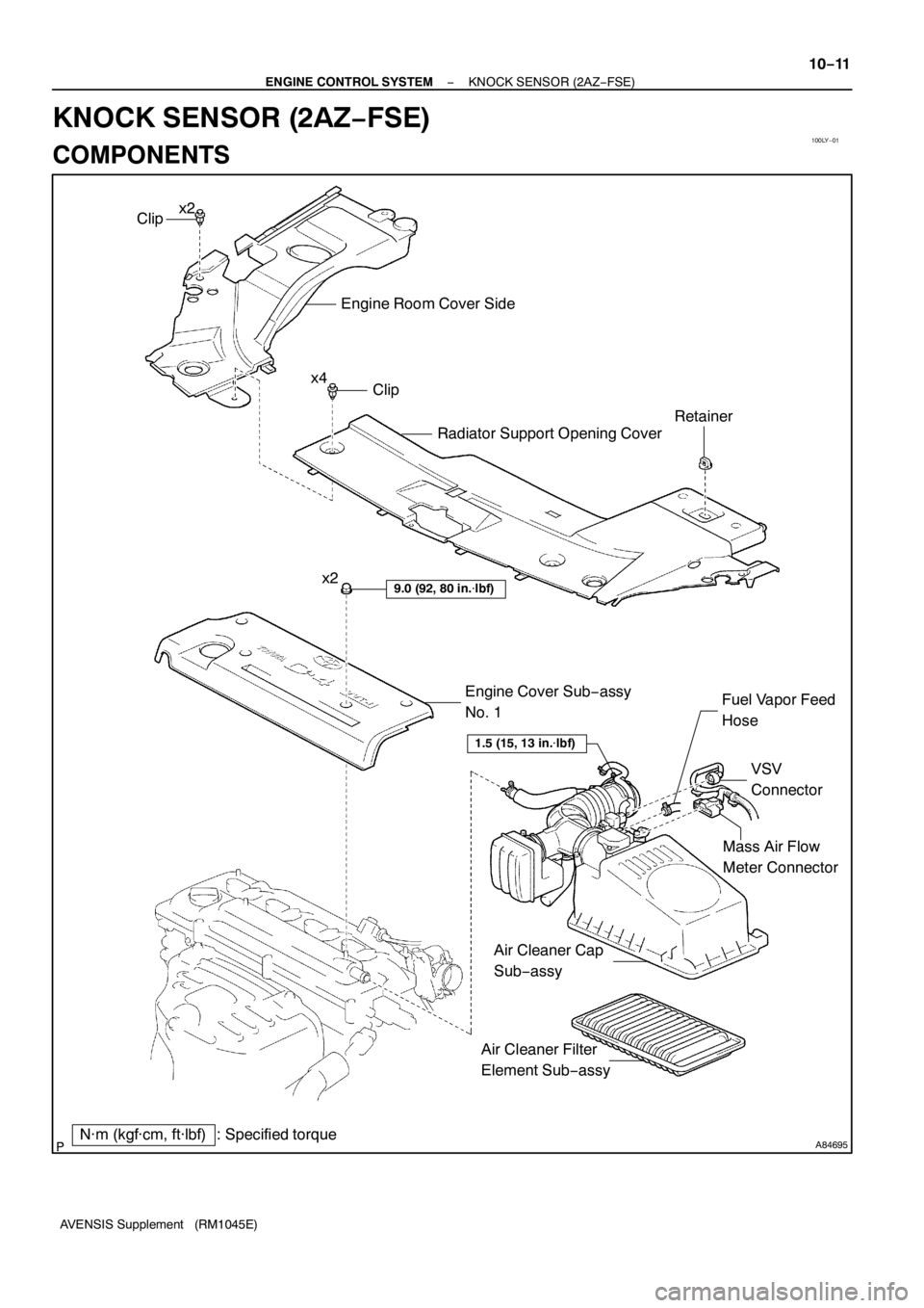
100LY−01
A84695
Mass Air Flow
Meter Connector
N·m (kgf·cm, ft·lbf) : Specified torqueEngine Cover Sub−assy
No. 1
9.0 (92, 80 in.�lbf)
VSV
Connector Fuel Vapor Feed
Hose
Clip
Engine Room Cover Side
Radiator Support Opening Cover
Clip
Retainer
x2
x4
1.5 (15, 13 in.�lbf)
Air Cleaner Filter
Element Sub−assy x2
Air Cleaner Cap
Sub−assy
− ENGINE CONTROL SYSTEMKNOCK SENSOR (2AZ−FSE)
10−11
AVENSIS Supplement (RM1045E)
KNOCK SENSOR (2AZ−FSE)
COMPONENTS
Page 4465 of 5135
A84696zNon−reusable part
N·m (kgf·cm, ft·lbf) : Specified torqueThrottle Body AssyThrottle Control Motor
Connector
zThrottle Body Gasket
Water By−pass Hose
No. 2
Water By−pass Hose
No. 1
9.0 (90, 80 in.�lbf)
x4
x4
21 (210, 15)Throttle Body Bracket
8.4 (86, 74 in.�lbf)
Ground TerminalWiring Harness
Protector
8.4 (86, 74 in.�lbf)
10−12
− ENGINE CONTROL SYSTEMKNOCK SENSOR (2AZ−FSE)
AVENSIS Supplement (RM1045E)
Page 4466 of 5135
A84701
N·m (kgf·cm, ft·lbf)
: Specified torque
zNon−reusable partzGasketzGasketFuel Tube Sub−assy
Fuel Pipe
Clamp
Fuel Pressure Pulsation
Damper Assy Fuel Pump Assy
zFuel Pump
Insulator
Fuel HoseFuel Pipe Sub−assy No. 1
zFuel Injector Back−up Ring No. 1
zFuel Injector Back−up Ring No. 2
zFuel Injector Back−up Ring No. 3
25 (255, 18)x2
zO−ring
9.0 (92, 80 in.�lbf)
30 (306, 22)
x2
33 (331, 24)
− ENGINE CONTROL SYSTEMKNOCK SENSOR (2AZ−FSE)
10−13
AVENSIS Supplement (RM1045E)
Page 4467 of 5135
A84709
N·m (kgf·cm, ft·lbf)
: Specified torque
zNon−reusable part zIntake Manifold
to Head Gasket No. 1Vacuum Hose
Pressure Sensor
Connector Intake Air Control Valve AssyVSV
ConnectorzIntake to Exhaust
Manifold Gasket Manifold Insulator No. 1
Charcoal Canister
Outlet Hose No. 1
Fuel Hose No. 1
Charcoal Canister
AssyIntake Manifold Vacuum Hose Vacuum Sensor
Connector
Vacuum Sensor
AssyVentilation Hose No. 1
30 (306, 22)
x2
30 (306, 22)
30 (306, 22)
9.5 (97, 84 in.�lbf)x2
x3
5.5 (56, 49 in.�lbf)
10−14
− ENGINE CONTROL SYSTEMKNOCK SENSOR (2AZ−FSE)
AVENSIS Supplement (RM1045E)
(From September, 2003)
05−393
AVENSIS Supplement (RM1045E)
DTC P0400 EXHAUST GAS RECIRCULATION FLOW
CIRCUIT DESCRIPTION
The EGR system recirculates exhaust gases")
 EGR Valve Opening
Position (Target)
Normal
Open
EGR Valve Position Sensor
Opening Position (Actual)Close
Abnormal
(Stuck)
Time
Threshold")
 : Specified torqueThrottle Body AssyThrottle Control Motor
Connector
zThrottle Body Gasket
Water By−pass Hose
No. 2
Water By−pass Hose
No. 1
9.0")

: Specified torque
zNon−reusable partzGasketzGasketFuel Tube Sub−assy
Fuel Pipe
Clamp
Fuel Pressure Pulsation
Damper Assy Fuel Pump Assy
zFuel Pump
Insulator
Fuel Ho")

: Specified torque
zNon−reusable part zIntake Manifold
to Head Gasket No. 1Vacuum Hose
Pressure Sensor
Connector Intake Air Control Valve AssyVSV
ConnectorzIntake to E")