Page 4592 of 5135
A88259
(g)(h)
(g)
A88260
Intake Manifold Intake Manifold
Insulator No. 1
A88261
(d)
(b)
(c)
(a)(b)(b)(b)
A88262
− FUELFUEL INJECTOR ASSY (2AZ−FSE)
11−15
AVENSIS Supplement (RM1045E)
(g) Disconnect the 2 vacuum hoses from the intake air control
valve and pressure sensor.
(h) Disconnect the pressure sensor connector.
(i) Remove the intake air control valve and gasket from the
cylinder head.
(j) Remove the intake manifold insulator No. 1 from the in-
take manifold.
(k) Remove the intake manifold from the vehicle.
16. REMOVE SURGE TANK STAY NO.1
(a) Disconnect the fuel pressure sensor connector.
(b) Disconnect the 4 fuel injector connectors.
(c) Remove the nut.
(d) Remove the wiring harness clamp, then remove the en-
gine wire.
(e) Remove the 2 bolts, then remove the surge tank stay No.
1.
Page 4595 of 5135

A88267
(a)
(b)
(b)(b)
(b)
(a)(a)(a)
A88268
Torx Socket T40
11−18
− FUELFUEL INJECTOR ASSY (2AZ−FSE)
AVENSIS Supplement (RM1045E)
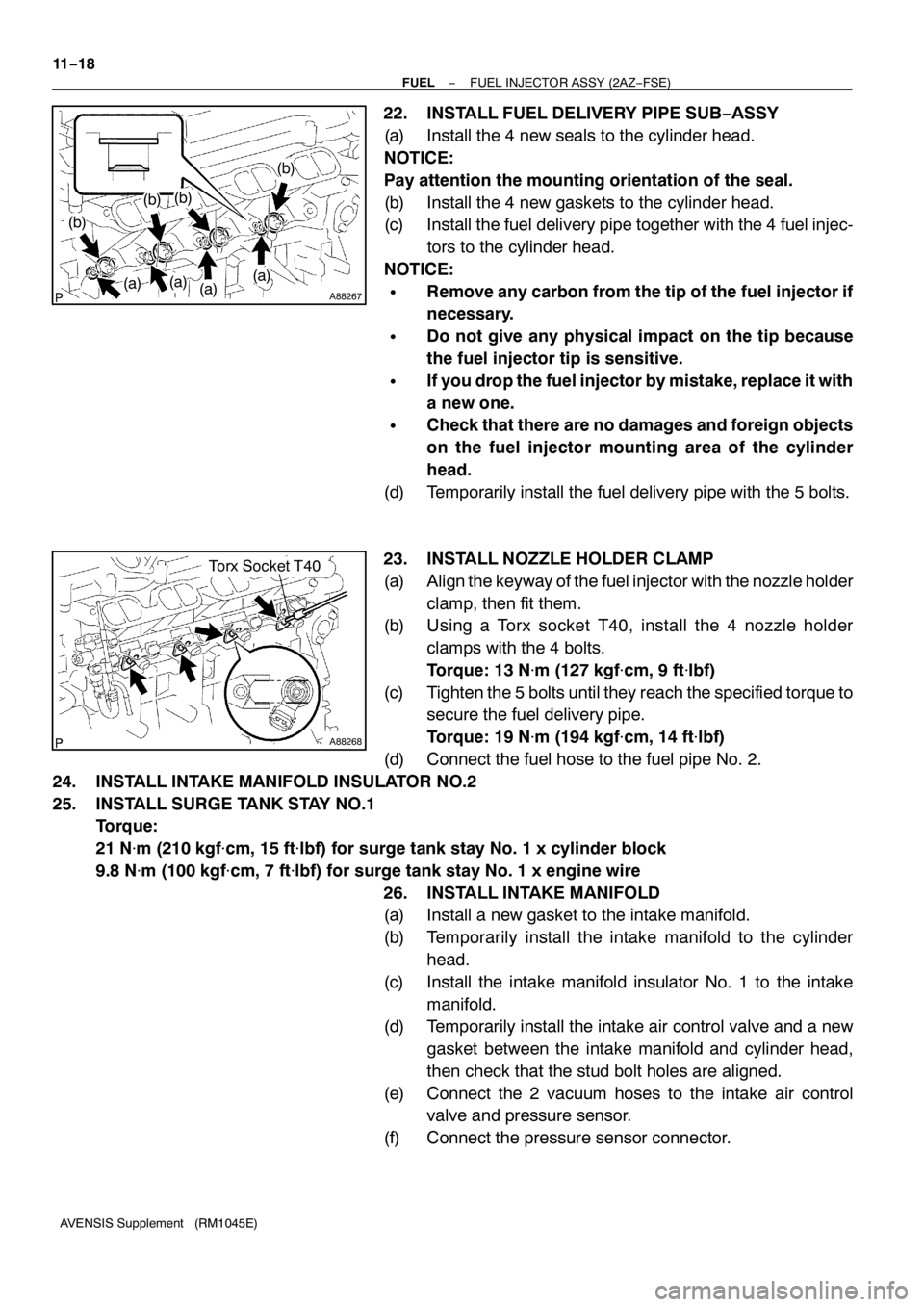
22. INSTALL FUEL DELIVERY PIPE SUB−ASSY
(a) Install the 4 new seals to the cylinder head.
NOTICE:
Pay attention the mounting orientation of the seal.
(b) Install the 4 new gaskets to the cylinder head.
(c) Install the fuel delivery pipe together with the 4 fuel injec-
tors to the cylinder head.
NOTICE:
SRemove any carbon from the tip of the fuel injector if
necessary.
SDo not give any physical impact on the tip because
the fuel injector tip is sensitive.
SIf you drop the fuel injector by mistake, replace it with
a new one.
SCheck that there are no damages and foreign objects
on the fuel injector mounting area of the cylinder
head.
(d) Temporarily install the fuel delivery pipe with the 5 bolts.
23. INSTALL NOZZLE HOLDER CLAMP
(a) Align the keyway of the fuel injector with the nozzle holder
clamp, then fit them.
(b) Using a Torx socket T40, install the 4 nozzle holder
clamps with the 4 bolts.
Torque: 13 N�m (127 kgf�cm, 9 ft�lbf)
(c) Tighten the 5 bolts until they reach the specified torque to
secure the fuel delivery pipe.
Torque: 19 N�m (194 kgf�cm, 14 ft�lbf)
(d) Connect the fuel hose to the fuel pipe No. 2.
24. INSTALL INTAKE MANIFOLD INSULATOR NO.2
25. INSTALL SURGE TANK STAY NO.1
Torque:
21 N�m (210 kgf�cm, 15 ft�lbf) for surge tank stay No. 1 x cylinder block
9.8 N�m (100 kgf�cm, 7 ft�lbf) for surge tank stay No. 1 x engine wire
26. INSTALL INTAKE MANIFOLD
(a) Install a new gasket to the intake manifold.
(b) Temporarily install the intake manifold to the cylinder
head.
(c) Install the intake manifold insulator No. 1 to the intake
manifold.
(d) Temporarily install the intake air control valve and a new
gasket between the intake manifold and cylinder head,
then check that the stud bolt holes are aligned.
(e) Connect the 2 vacuum hoses to the intake air control
valve and pressure sensor.
(f) Connect the pressure sensor connector.
Page 4596 of 5135

A88257
12345
A88256
(i)
(j)
(i)
−
FUEL FUEL INJECTOR ASSY (2AZ −FSE)
11 −19
AVENSIS Supplement (RM1045E)
(g) Using a Torx socket E7, install and tighten the 2 stud bolts
to secure the intake manifold, intake air control valve and
gasket.
Torque: 9.5 N �m (97 kgf �cm, 84 in. �lbf)
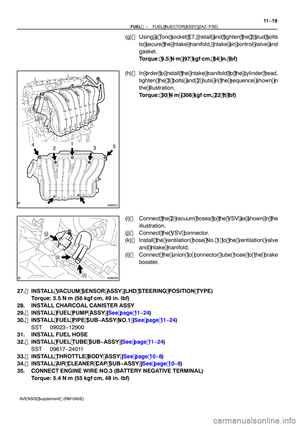
(h) In order to install the intake manifold to the cylinder head, tighten the 3 bolts and 2 nuts in the sequence shown in
the illustration.
Torque: 30 N �m (306 kgf �cm, 22 ft �lbf)
(i) Connect the 2 vacuum hoses to the VSV as shown in the illustration.
(j) Connect the VSV connector.
(k) Install the ventilation hose No. 1 to the ventilation valve and intake manifold.
(l) Connect the union to connector tube hose to the brake booster.
27. INSTALL VACUUM SENSOR ASSY (LHD STEERING POSITION TYPE) Torque: 5.5 N �m (56 kgf �cm, 49 in. �lbf)
28. INSTALL CHARCOAL CANISTER ASSY
29. INSTALL FUEL PUMP ASSY (See page 11 −24)
30. INSTALL FUEL PIPE SUB −ASSY NO.1 (See page 11 −24)
SST 09023 −12900
31. INSTALL FUEL HOSE
32. INSTALL FUEL TUBE SUB −ASSY (See page 11 −24)
SST 09617 −24011
33. INSTALL THROTTLE BODY ASSY (See page 10 −8)
34. INSTALL AIR CLEANER CAP SUB −ASSY (See page 10 −8)
35. CONNECT ENGINE WIRE NO.3 (BATTERY NEGATIVE TERMINAL) Torque: 5.4 N �m (55 kgf �cm, 48 in. �lbf)
Page 4601 of 5135

A88284Battery
A13269B12608
A91714
Hand−held Tester
11 −6
−
FUEL FUEL SYSTEM (2AZ −FSE)
AVENSIS Supplement (RM1045E)
(b) When not using the hand −held tester.
(1) Connect the positive (+) lead form the battery to ter- minal 4 of the connector, and connect the negative
(− ) lead to terminal 5.
(2) Check that the pump operates.
3. CHECK FUEL PUMP OPERATION (HIGH PRESSURE)
(a) Remove the engine cover No. 1 (see page 10 −8) .
(b) Start the engine.
(c) Using a sound scope, hear the operating sound of the pump.
If there is no sound, replace the fuel pump.
(d) Stop the engine.
(e) Reinstall the engine cover No. 1 (see page 10 −8) .
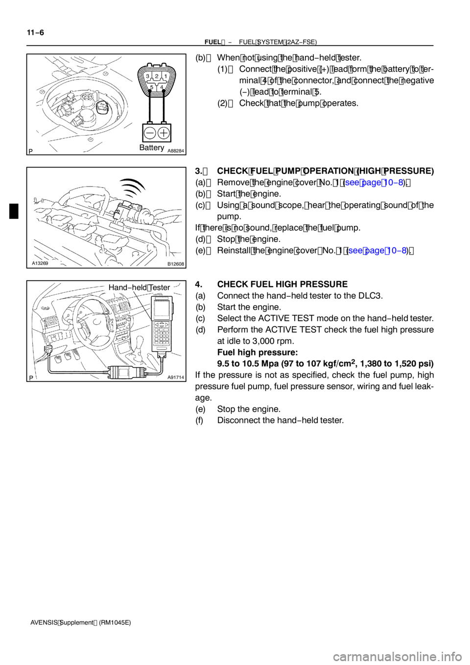
4. CHECK FUEL HIGH PRESSURE
(a) Connect the hand −held tester to the DLC3.
(b) Start the engine.
(c) Select the ACTIVE TEST mode on the hand −held tester.
(d) Perform the ACTIVE TEST check the fuel high pressure at idle to 3,000 rpm.
Fuel high pressure:
9.5 to 10.5 Mpa (97 to 107 kgf/cm
2, 1,380 to 1,520 psi)
If the pressure is not as specified, check the fuel pump, high
pressure fuel pump, fuel pressure sensor, wiring and fuel leak-
age.
(e) Stop the engine.
(f) Disconnect the hand −held tester.
Page 4605 of 5135

100M3−01
321 4 5
−20
020 40 60
80100 0.1 0.2 0.3 0.51 235 1020 30
Temperature_C(_F)
Resistance k�
(−4) (32) (68) (140)(104) (212)(176)
A89885
THA VG
E2G+B
E2
A86426
VTA
VC E2
10−22
− ENGINE CONTROL SYSTEMECD SYSTEM (1CD−FTV)(From September, 2003)
AVENSIS Supplement (RM1045E)
INSPECTION
1. INSPECT MASS AIR FLOW METER
(a) Check the operation.
(1) Apply battery voltage across terminals 3 (+B) and 4
(E2G).
(2) Using a voltmeter, connect the positive (+) tester
probe to terminal VG, and negative (−) tester probe
to terminal E2G.
(3) Blow air into the MAF meter, then check that the
voltage fluctuates.
(b) Inspect the resistance.
(1) Using an ohmmeter, measure the resistance be-
tween terminals 2 (THA) and 1 (E2).
Resistance:
12.5 to 16.9 k�at−20_C(−4_F)
2.19 to 2.67 k�at 20_C (68_F)
0.50 to 0.68 k�at 60_C (140_F)
If the result is not as specified, replace the MAF meter.
2. INSPECT INTAKE SHUTTER ASSY
(a) Inspect the resistance of the throttle position sensor.
(1) Using an ohmmeter, measure the resistance be-
tween terminals 1 (VC) and 2 (E2).
Resistance: 4.0 to 8.0 k�
If the result is not as specified, replace the intake shutter.
Page 4606 of 5135

S01196S01699
30
20
10
5
3
02040 0.11
0.3
0.2 0.52
60 80 100 −20
(−4) (104) (140) (176)(32) (68) (212)
Z17274
Ohmmeter
Acceptable
Temperature_C(_F)
Resistance k�
THF E2
A30331
30
20
10
5
3
2
1
0.5
0.3
0.2
0.1
−20 0
20 4060
80 100
F14741(−4) (104) (140) (176)(32) (68) (212)
A56276
Temperature_C(_F)
Resistance k�
− ENGINE CONTROL SYSTEMECD SYSTEM (1CD−FTV)(From September, 2003)
10−23
AVENSIS Supplement (RM1045E)
3. INSPECT DIESEL ENGINE ENGINE COOLANT
TEMPERATURE SENSOR
(a) Inspect the resistance.
(1) Using an ohmmeter, measure the resistance be-
tween the terminals.
Resistance:
2.32 to 2.59 k�at 20_C (68_F)
0.310 to 0.326 k�at 80_C (176_F)
If the result is not as specified, replace the diesel engine engine
coolant temperature sensor.
NOTICE:
In case of checking the water temperature sensor in the wa-
ter, be careful not to allow water to go into the terminals. Af-
ter checking, wipe out the sensor.
4. INSPECT FUEL TEMPERATURE SENSOR
(a) Inspect the resistance.
(1) Using an ohmmeter, measure the resistance be-
tween the terminals.
Resistance:
2.21 to 2.69 k�at 20_C (68_F)
0.287 to 0.349 k�at 80_C (176_F)
If the result is not as specified, replace the fuel temperature sen-
sor.
5. INSPECT DIESEL TURBO INLET AIR TENPERATURE
SENSOR
(a) Inspect the resistance.
(1) Using an ohmmeter, measure the resistance be-
tween the terminals.
Resistance:
2.21 to 2.65 k�at 20_C (68_F)
If the result is not as specified, replace the diesel turbo inlet air
temperature sensor.
Page 4607 of 5135

A56277
NE−NE+
A57060
NE− NE+
B16200
10−24
− ENGINE CONTROL SYSTEMECD SYSTEM (1CD−FTV)(From September, 2003)
AVENSIS Supplement (RM1045E)
6. INSPECT CRANKSHAFT POSITION SENSOR
(a) Inspect the resistance.
(1) Using an ohmmeter, measure the resistance be-
tween the terminals.
Resistance:
1630 to 2740�at cold
2065 to 3225�at hot
If the result is not as specified, replace the crankshaft position
sensor.
NOTICE:
”Cold” and ”Hot” in the above sentences mean the temper-
ature of the sensor itself. ”Cold” is from−10_C (14_F) to
50_C (122_F) and ”Hot” is from 50_C (122_F) to 100_C
(212_F).
7. INSPECT CAMSHAFT POSITION SENSOR
(a) Inspect the resistance.
(1) Using an ohmmeter, measure the resistance be-
tween the terminals.
Resistance:
1630 to 2740�at cold
2065 to 3225�at hot
If the result is not as specified, replace the camshaft position
sensor.
NOTICE:
”Cold” and ”Hot” in the above sentences mean the temper-
ature of the sensor itself. ”Cold” is from−10_C (14_F) to
50_C (122_F) and ”Hot” is from 50_C (122_F) to 100_C
(212_F).
8. INSPECT EDU RELAY
(a) Inspect the resistance.
(1) Using an ohmmeter, measure the resistance be-
tween the terminals.
Specified condition:
Tester ConnectionSpecified Condition
3−510 k�or Higher
3−5
Below 1�
(When battery voltage is applied to
terminals 1 and 2)
If the result is not as specified, replace the EDU relay.
Page 4609 of 5135

100M2−01
A75903
Air
A66060
VG
EVGE12 ECM Connector
−
ENGINE CONTROL SYSTEM ECD SYSTEM (1CD−FTV)(From September, 2003)
10 −19
AVENSIS Supplement (RM1045E)
ECD SYSTEM (1CD −FTV)(From September, 2003)
ON −VEHICLE INSPECTION
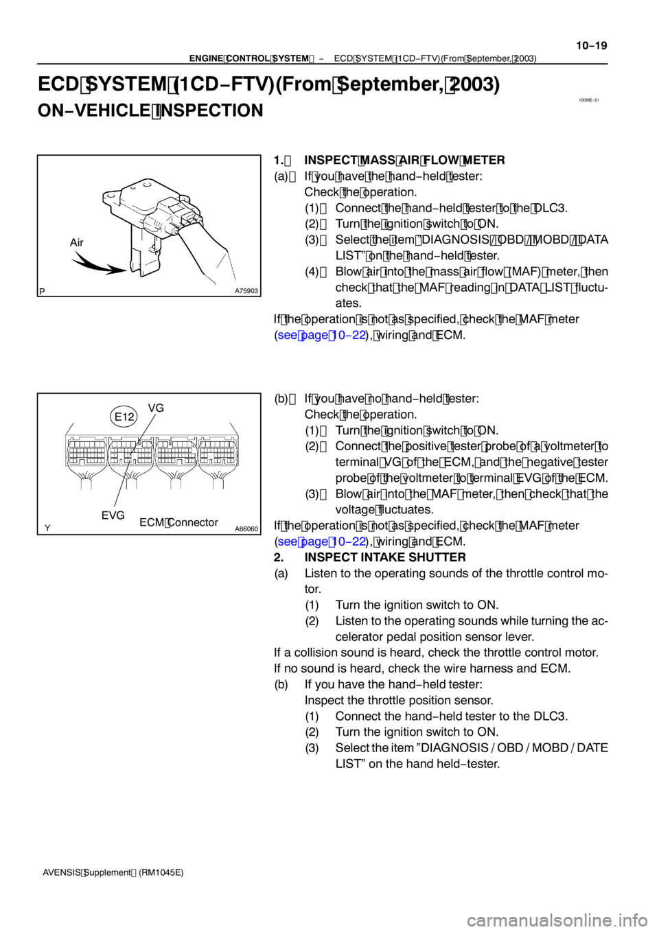
1. INSPECT MASS AIR FLOW METER
(a) If you have the hand −held tester:
Check the operation.
(1) Connect the hand −held tester to the DLC3.
(2) Turn the ignition switch to ON.
(3) Select the item ”DIAGNOSIS / OBD / MOBD / DATA
LIST” on the hand −held tester.
(4) Blow air into the mass air flow (MAF) meter, then
check that the MAF reading in DATA LIST fluctu-
ates.
If the operation is not as specified, check the MAF meter
(see page 10 −22), wiring and ECM.
(b) If you have no hand −held tester:
Check the operation.
(1) Turn the ignition switch to ON.
(2) Connect the positive tester probe of a voltmeter to
terminal VG of the ECM, and the negative tester
probe of the voltmeter to terminal EVG of the ECM.
(3) Blow air into the MAF meter, then check that the voltage fluctuates.
If the operation is not as specified, check the MAF meter
(see page 10 −22), wiring and ECM.
2. INSPECT INTAKE SHUTTER
(a) Listen to the operating sounds of the throttle control mo- tor.
(1) Turn the ignition switch to ON.
(2) Listen to the operating sounds while turning the ac-
celerator pedal position sensor lever.
If a collision sound is heard, check the throttle control motor.
If no sound is heard, check the wire harness and ECM.
(b) If you have the hand −held tester:
Inspect the throttle position sensor.
(1) Connect the hand −held tester to the DLC3.
(2) Turn the ignition switch to ON.
(3) Select the item ”DIAGNOSIS / OBD / MOBD / DATE LIST” on the hand held −tester.