Page 4702 of 5135
A77327
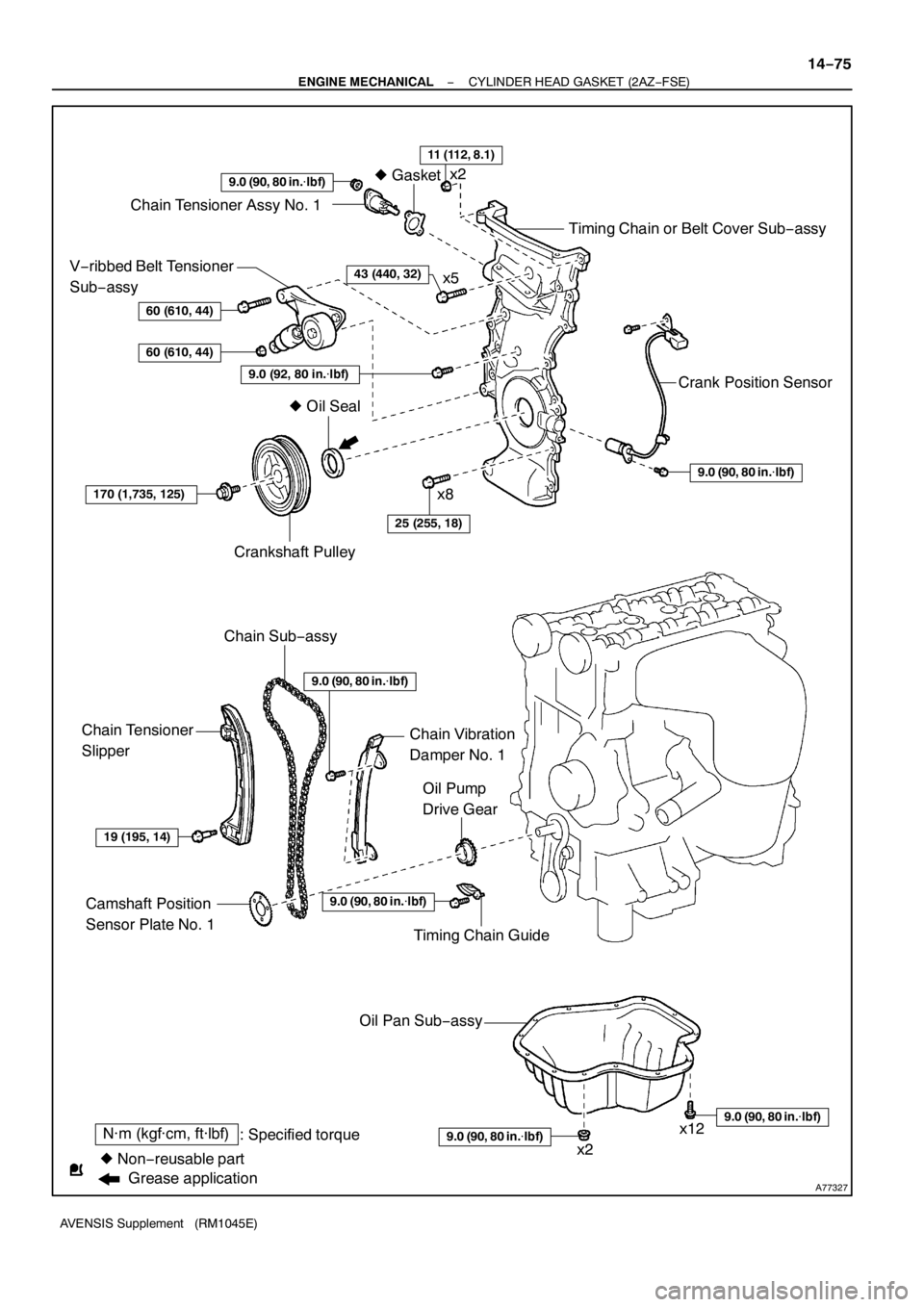
N·m (kgf·cm, ft·lbf)
: Specified torque
zNon−reusable partzGasket
9.0 (90, 80 in.�lbf)
Chain Tensioner Assy No. 1
Timing Chain or Belt Cover Sub−assy
Crank Position Sensor
9.0 (90, 80 in.�lbf)
V−ribbed Belt Tensioner
Sub−assy
60 (610, 44)
60 (610, 44)
9.0 (92, 80 in.�lbf)
170 (1,735, 125)
Crankshaft Pulley
Chain Sub−assy
25 (255, 18)
Chain Tensioner
Slipper
19 (195, 14)
Camshaft Position
Sensor Plate No. 1
Oil Pump
Drive Gear
Chain Vibration
Damper No. 1
zOil Seal
Timing Chain Guide
9.0 (90, 80 in.�lbf)
Oil Pan Sub−assy
9.0 (90, 80 in.�lbf)
9.0 (90, 80 in.�lbf)
11 (112, 8.1)
43 (440, 32)
9.0 (90, 80 in.�lbf)
x2
x5
x8
x2x12
Grease application
− ENGINE MECHANICALCYLINDER HEAD GASKET (2AZ−FSE)
14−75
AVENSIS Supplement (RM1045E)
Page 4717 of 5135
A89211
N·m (kgf·cm, ft·lbf)
: Specified torque
zNon−reusable part zO−ringzGasket zBack−Up Ring No. 1
20 (208, 15)
21 (210, 15)21 (210, 15)
20 (208, 15)
Engine Coolant
Temperature Sensor
Engine Oil Pressure
Switch Assy
Surge Tank Stay No. 1
Insulator No. 2
zE−ring
zBack−Up Ring No. 3
zFuel Injector Seal
13 (127, 9.0)
Fuel Delivery
Pipe Sub−assy
Nozzle Holder Clamp
Knock Sensor
15 (153, 11)
Fuel Injector
zBack−Up Ring No. 2zO−ring19 (194, 14)
14−22
− ENGINE MECHANICALPARTIAL ENGINE ASSY (2AZ−FSE)
AVENSIS Supplement (RM1045E)
Page 4718 of 5135

(b)
(a)
(a)
(b)
A93661
(a)
(a) (a)
(a) (b)
(a)
(b)
13
−12
−
INTAKE TURBOCHARGER SUB −ASSY (1CD −FTV)(From
September, 2003)
AVENSIS Supplement (RM1045E)
REPLACEMENT
1. RE")
1308N−01
A84393
(a)
(b)
(a)
(a)
(b)
A93661
(a)
(a) (a)
(a) (b)
(a)
(b)
13
−12
−
INTAKE TURBOCHARGER SUB −ASSY (1CD −FTV)(From
September, 2003)
AVENSIS Supplement (RM1045E)
REPLACEMENT
1. REMOVE ENGINE UNDER COVER SUB −ASSY NO.1
2. DRAIN ENGINE COOLANT (See page 16 −19)
3. REMOVE RADIATOR SUPPORT OPENING COVER
4. REMOVE ENGINE COVER SUB −ASSY NO.1
(a) Remove the 5 nuts and engine cover.
5. REMOVE VACUUM RESERVOIR SUB −ASSY
(a) Disconnect the 2 vacuum hoses and connector.
(b) Remove the 2 bolts and vacuum reservoir.
6. REMOVE DIFFERENTIAL PRESSURE SENSOR ASSY (See page 14 −108)
7. DISCONNECT ENGINE WIRE (See page 14 −138)
8. REMOVE AIR CLEANER ASSY
(a) Disconnect the PCV hose and connector.
(b) Remove the air cleaner cap with the air cleaner hose.
(c) Remove the air cleaner filter element.
(d) Remove the 3 bolts and air cleaner case.
9. REMOVE AIR TUBE NO.1
(a) Remove the 3 bolts and nut, then separate the air tubeNo. 1.
(b) Loosen the hose clamp bolts.
10. REMOVE FUEL FILTER ASSY (See Pub. No. RM1018E on page 11 −82)
Page 4721 of 5135
A85753
A79164
A79444
A92433
−
INTAKE TURBOCHARGER SUB −ASSY (1CD −FTV)(From
September, 2003)13 −15
AVENSIS Supplement (RM1045E)
21. REMOVE EXHAUST GAS TEMPERATURE SENSOR (See page 14 −108)
SST 09023 −38400
22. REMOVE VACUUM TRANSMITTING PIPE SUB −ASSY NO.1 (See page 14 −108)
SST 09023 −38200
23. REMOVE VACUUM TRANSMITTING PIPE SUB −ASSY NO.2 (See page 14 −108)
SST 09023 −38200
24. REMOVE MANIFOLD STAY NO.2
(a) Remove the bolt and nut, then remove the manifold stayNo. 2.
25. REMOVE MANIFOLD STAY
(a) Remove the 4 bolts and manifold stay.
26. REMOVE EXHAUST MANIFOLD CONVERTER SUB−ASSY
(a) Remove the 3 nuts, manifold converter and gasket.
27. REMOVE TURBOCHARGER STAY
(a) Remove the 2 bolts and 2 nuts, then remove the turbo-
charger stay.
Page 4724 of 5135
(From
September, 2003)
AVENSIS Supplement (RM1045E)
38. INSTALL MANIFOLD STAY NO.2
(a) Install the manifold stay No. 2, then temporarily")
A85753
13−18−
INTAKE TURBOCHARGER SUB −ASSY (1CD −FTV)(From
September, 2003)
AVENSIS Supplement (RM1045E)
38. INSTALL MANIFOLD STAY NO.2
(a) Install the manifold stay No. 2, then temporarily tighten the bolt.
(b) Temporarily tighten the nut while pushing the manifold
stay No. 2 toward the cylinder head.
Torque: 8.0 N �m (82 kgf �cm, 71 in. �lbf)
HINT:
No clearance between the stay and cylinder head should be
confirmed.
(c) Tighten the bolt.
Torque: 56 N �m (571 kgf �cm, 41 ft �lbf)
(d) Tighten the nut. Torque: 56 N �m (571 kgf �cm, 41 ft �lbf)
39. INSTALL VACUUM TRANSMITTING PIPE SUB −ASSY NO.2 (See page 14 −108)
SST 09023 −38200
40. INSTALL VACUUM TRANSMITTING PIPE SUB −ASSY NO.1 (See page 14 −108)
SST 09023 −38200
41. INSTALL EXHAUST GAS TEMPERATURE SENSOR (See page 14 −108)
SST 09023 −38400
42. INSTALL EGR PIPE INSULATOR Torque: 12 N �m (122 kgf �cm, 8.9 ft �lbf)
43. INSTALL GENERATOR ASSY (See Pub. No. RM1018E on page 19 −29)
44. INSTALL EXHAUST MANIFOLD HEAT INSULATOR NO.2 Torque: 12 N �m (122 kgf �cm, 8.9 ft �lbf)
45. INSTALL TURBO INSULATOR NO.1 Torque: 20 N �m (204 kgf �cm, 15 ft �lbf)
46. INSTALL TURBO INSULATOR NO.2 Torque: 20 N �m (204 kgf �cm, 15 ft �lbf)
47. INSTALL EXHAUST PIPE ASSY (W/ COLD AREA) Torque: 7.5 N �m (76 kgf �cm, 66 in. �lbf)
48. INSTALL EXHAUST PIPE ASSY FRONT (See page 15 −6)
49. INSTALL FLOOR PANEL BRACE FRONT (See page 15 −6)
50. INSTALL HEATER BRACKET (W/ COLD AREA)
Torque: 7.5 N �m (76 kgf �cm, 66 in. �lbf)
51. INSTALL HEATER PUMP ASSY (W/ COLD AREA)
Torque: 7.5 N �m (76 kgf �cm, 66 in. �lbf)
52. INSTALL FUEL FILTER ASSY (See Pub. No. RM1018E on page 11 −82)
Page 4725 of 5135
 0to5mm
(0 to 0.1969 in.) 0to2mm
(0 to 0.0787 in.) *1*2
*2: *1:
Turbocharger Side
Intercooler Side
A93662
Turbocharger Side:
Intercooler Side: Upward
90_
Cl a m p
B")
A84387
2to7mm
(0.0787 to
0.2756 in.) 0to5mm
(0 to 0.1969 in.) 0to2mm
(0 to 0.0787 in.) *1*2
*2: *1:
Turbocharger Side
Intercooler Side
A93662
Turbocharger Side:
Intercooler Side: Upward
90_
Cl a m p
Bolt
90_
Cl a m p
Bolt
Front
−
INTAKE TURBOCHARGER SUB −ASSY (1CD −FTV)(From
September, 2003)13 −19
AVENSIS Supplement (RM1045E)
53. INSTALL AIR TUBE NO.1
(a) Install the air hose and hose clamps as shown in the il-
lustration.
(b) Tighten the hose clamps as shown in the illustration. Torque: 6.0 N �m (61 kgf �cm, 53 in. �lbf)
(c) Install the air tube No. 1 with the 3 bolts and nut. Torque: 25 N �m (255 kgf �cm, 18 ft �lbf)
54. INSTALL DIFFERENTIAL PRESSURE SENSOR ASSY (See page 14 −108)
55. INSTALL AIR CLEANER ASSY
Torque: 7.0 N �m (71 kgf �cm, 62 in. �lbf)
56. INSTALL VACUUM RESERVOIR SUB −ASSY
Torque: 8.3 N �m (85 kgf �cm, 73 in. �lbf)
57. INSTALL ENGINE COVER SUB −ASSY NO.1
Torque: 8.0 N �m (82 kgf �cm, 71 in. �lbf)
58. ADD ENGINE COOLANT (See page 16 −19)
59. CHECK ENGINE OIL LEVEL
60. CHECK FOR ENGINE COOLANT LEAKS (See page 16 −15)
61. CHECK FOR ENGINE OIL LEAKS
62. CHECK FOR FUEL LEAKS (See page 11 −46)
63. CHECK FOR EXHAUST GAS LEAKS
Page 4731 of 5135

AVENSIS Supplement (RM1045E)
OVERHAUL
HINT:
Overhaul the RH side follow")
300N6−01
C53220F45751
SST
F13686
Hold
Turn
C80291
F44775
30−4
− DRIVE SHAFT / PROPELLER SHAFTFRONT DRIVE SHAFT (2AZ−FSE)
AVENSIS Supplement (RM1045E)
OVERHAUL
HINT:
Overhaul the RH side following the same procedure as for the LH side.
1. DRAIN AUTOMATIC TRANSAXLE FLUID (A/T TRANSAXLE)
(a) Remove the drain plug and gasket, and then drain the ATF.
(b) Install a new gasket and drain plug.
Torque: 49 N�m (500 kgf�cm, 36 ft�lbf)
2. REMOVE FRONT WHEEL
3. REMOVE ENGINE UNDER COVER LH
4. SEPARATE FRONT AXLE HUB LH NUT
(a) Using SST and a hammer, unstake the staked part of the
nut.
SST 09930−00010
(b) While applying the brake, remove the axle hub LH nut.
NOTICE:
Loosen the staked part of the lock nut completely, other-
wise the screw of the drive shaft may become damaged.
5. SEPARATE FRONT STABILIZER LINK ASSY LH
(a) Remove the nut and separate the front stabilizer link assy
LH from the shock absorber assy LH.
HINT:
If the ball joint turns together with the nut, use a hexagon
wrench (6 mm) to hold the stud.
6. DISCONNECT SPEED SENSOR FRONT LH
(a) Remove the bolt, and disconnect the speed sensor wire
and flexible hose from the shock absorber.
(b) Remove the bolt, and disconnect the speed sensor from
the steering knuckle.
NOTICE:
SBe careful not to damage the speed sensor.
SPrevent foreign matter from adhering to the speed
sensor.
Page 4732 of 5135
F40217
SSTTurn
Hold
C80293
D27403
F40148SST
− DRIVE SHAFT / PROPELLER SHAFTFRONT DRIVE SHAFT (2AZ−FSE)
30−5
AVENSIS Supplement (RM1045E)
7. SEPARATE TIE ROD END SUB−ASSY LH
(a) Remove the cotter pin and nut.
(b) Using SST, separate the tie rod end sub−assy LH from the
steering knuckle.
SST 09628−62011
8. SEPARATE FRONT SUSPENSION ARM SUB−ASSY
LOWER NO.1LH
(a) Remove the bolt and 2 nuts, and separate the front sus-
pension arm sub−assy lower No.1LH from the lower ball
joint.
9. SEPARATE FRONT AXLE ASSY LH
(a) Using a plastic hammer, separate the front drive shaft
assy LH from the axle hub.
NOTICE:
Be careful not to damage the boot and speed sensor rotor.
10. REMOVE FRONT DRIVE SHAFT ASSY LH
(a) Using SST, remove the front drive shaft assy LH.
SST 09520−01010, 09520−24010 (09520−32040)
NOTICE:
SBe careful not to damage the oil seal, boot and dust
cover.
SBe careful not to drop the drive shaft assy.

: Specified torque
zNon−reusable part zO−ringzGasket zBack−Up Ring No. 1
20 (208, 15)
21 (210, 15)21 (210, 15)
20 (208, 15)
Engine Coolant
Temperature Sensor
Engin")
(From
September, 2003)13 −15
AVENSIS Supplement (RM1045E)
21. REMOVE EXHAUST GAS TEMPERATURE SENSOR (See page 14 −108)")

30−5
AVENSIS Supplement (RM1045E)
7. SEPARATE TIE ROD END SUB−ASSY LH
(a) Remove the cott")