Page 4742 of 5135

C81796F45254
(A)
C83851
C83155
C80293
− DRIVE SHAFT / PROPELLER SHAFTFRONT DRIVE SHAFT (2AZ−FSE)
30−15
AVENSIS Supplement (RM1045E)
HINT:
For dimension (A), refer to the following table.
Drive shaft typeDimension (A) mm (in.)
LH546.1(21.50)�á5.0 (0.20)
RH884.0 (34.80)�á5.0 (0.20)
41. INSTALL FRONT DRIVE SHAFT ASSY LH
(a) Coat the inboard joint shaft assy LH spline with gear oil.
(b) Align the shaft splines and install the drive shaft assy LH
with a brass bar and hammer.
NOTICE:
SSet the snap ring with the opening side facing down-
wards.
SBe careful not to damage the oil seal, boot and dust
cover.
42. INSTALL FRONT DRIVE SHAFT ASSY RH (RH DRIVE
SHAFT)
(a) Coat the inboard joint shaft assy RH spline with gear oil.
(b) Align the shaft splines and install the drive shaft assy RH
with the 2 bolts.
Torque: 64 N�m (650 kgf�cm, 47 ft�lbf)
NOTICE:
Do not damage the oil seal, boot and dust cover.
43. INSTALL FRONT AXLE ASSY LH
(a) Install the drive shaft assy LH to the front axle assy LH.
NOTICE:
SBe careful not to damage the outboard joint boot.
SBe careful not to damage the speed sensor rotor.
44. INSTALL FRONT SUSPENSION ARM SUB−ASSY
LOWER NO.1LH
(a) Install the lower ball joint to the front suspension arm sub−
assy lower No.1LH with the bolt and 2 nuts.
Torque: 89 N�m (908 kgf�cm, 66 ft�lbf)
Page 4743 of 5135

F44775
C80291
F13686
Hold
Turn
C68609
30−16
− DRIVE SHAFT / PROPELLER SHAFTFRONT DRIVE SHAFT (2AZ−FSE)
AVENSIS Supplement (RM1045E)
45. INSTALL TIE ROD END SUB−ASSY LH
(a) Install the tie rod end sub−assy LH to the steering knuckle with the nut.
Torque: 49 N�m (500 kgf�cm, 36 ft�lbf)
(b) Install a new cotter pin.
NOTICE:
If the holes for the cotter pin are not aligned, tighten the nut up to 60_further.
46. CONNECT SPEED SENSOR FRONT LH
(a) Install the speed sensor front LH to the steering knuckle
with the bolt.
Torque: 8.0 N�m (82 kgf�cm, 71in.�lbf)
(b) Connect the speed sensor wire and flexible hose to the
shock absorber with the bolt.
Torque:19N�m(194 kgf�cm,14ft�lbf)
NOTICE:
SBe careful not to damage the speed sensor.
SKeep the speed sensor clean.
SDo not twist the sensor wire when installing the sen-
sor.
47. INSTALL FRONT STABILIZER LINK ASSY LH
(a) Install the front stabilizer link assy LH with the nut.
Torque: 74 N�m (755 kgf�cm, 55 ft�lbf)
HINT:
If the ball joint turns together with the nut, use a hexagon
wrench (6 mm) to hold the stud.
48. INSTALL FRONT AXLE HUB LH NUT
(a) Install a new axle hub LH nut.
Torque: 216N�m (2,200 kgf�cm,159 ft�lbf)
(b) Using a chisel and hammer, stake the axle hub LH nut.
Page 4744 of 5135
− DRIVE SHAFT / PROPELLER SHAFTFRONT DRIVE SHAFT (2AZ−FSE)
30−17
AVENSIS Supplement (RM1045E)
49. INSTALL ENGINE UNDER COVER LH
50. INSTALL FRONT WHEEL
Torque:103 N�m(1,050 kgf�cm, 76 ft�lbf)
51. ADD AUTOMATIC TRANSAXLE FLUID (A/T TRANSAXLE)
(SEE PUB. NO. RM1018E ON PAGE 40−2)
52. INSPECT AND ADJUST AUTOMATIC TRANSAXLE FLUID (A/T TRANSAXLE)
(SEE PUB. NO. RM1018E ON PAGE 40−2)
53. INSPECT AND ADJUST FRONT WHEEL ALIGNMENT (SEE PUB. NO. RM1018E ON PAGE 26−6)
54. CHECK ABS SPEED SENSOR SIGNAL
(a) ABD WITH EBD & BA & TRAC & VSC SYSTEM (SEE PUB. NO. RM1018E ON PAGE 5−756)
Page 4749 of 5135

B08016
O−ring
A85926
A56695
A79175
SST SST
17
−12
−
LUBRICATION OIL PUMP ASSY (1CD −FTV)(From September, 2003)
AVENSIS Supplement (RM1045E)
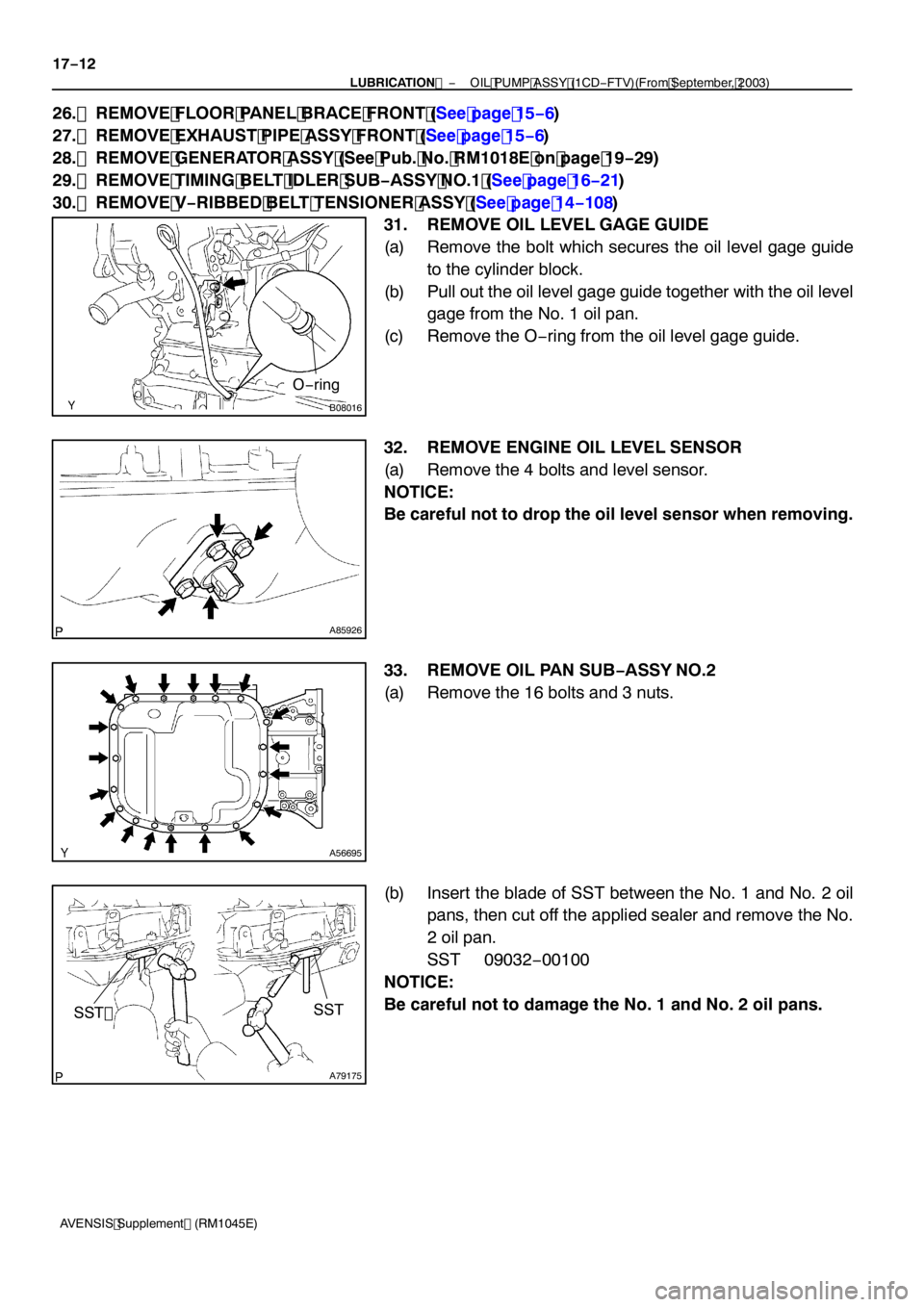
26. REMOVE FLOOR PANEL BRACE FRONT (See page 15 −6)
27. REMOVE EXHAUST PIPE ASSY FRONT (See page 15 −6)
28. REMOVE GENERATOR ASSY (See Pub. No. RM1018E on page 19 −29)
29. REMOVE TIMING BELT IDLER SUB −ASSY NO.1 (See page 16 −21)
30. REMOVE V −RIBBED BELT TENSIONER ASSY (See page 14 −108)
31. REMOVE OIL LEVEL GAGE GUIDE
(a) Remove the bolt which secures the oil level gage guide to the cylinder block.
(b) Pull out the oil level gage guide together with the oil level gage from the No. 1 oil pan.
(c) Remove the O −ring from the oil level gage guide.
32. REMOVE ENGINE OIL LEVEL SENSOR
(a) Remove the 4 bolts and level sensor.
NOTICE:
Be careful not to drop the oil level sensor when removing.
33. REMOVE OIL PAN SUB −ASSY NO.2
(a) Remove the 16 bolts and 3 nuts.
(b) Insert the blade of SST between the No. 1 and No. 2 oil pans, then cut off the applied sealer and remove the No.
2 oil pan.
SST 09032 −00100
NOTICE:
Be careful not to damage the No. 1 and No. 2 oil pans.
Page 4750 of 5135
A56696
B08009
A56697
A56698
−
LUBRICATION OIL PUMP ASSY (1CD −FTV)(From September, 2003)
17 −13
AVENSIS Supplement (RM1045E)
34. REMOVE OIL STRAINER SUB −ASSY
(a) Remove the 2 bolts and 2 nuts, then remove the oil strain- er and gasket.
35. REMOVE OIL PAN INSULATOR
(a) Remove the bolt and oil pan insulator.
36. REMOVE OIL PAN SUB −ASSY
(a) Remove the 19 bolts and 3 nuts.
(b) Using a screwdriver, remove the oil pan by prying be-
tween the cylinder block and No. 1 oil pan.
NOTICE:
Be careful not to damage the cylinder block and No. 1 oil
pan.
37. REMOVE CRANKSHAFT POSITION SENSOR (See page 14 −138)
Page 4752 of 5135
A57099
A56702
−
LUBRICATION OIL PUMP ASSY (1CD −FTV)(From September, 2003)
17 −15
AVENSIS Supplement (RM1045E)
(f) Install the oil pump with the 9 bolts.
Torque: 31 N �m (320 kgf �cm, 23 ft �lbf)
(g) Measure the oil pump rotating torque. (1) Check that the pump rotates smoothly without mak- ing a noise.
(2) Using a torque wrench, check the pump rotating torque.
Rotating torque: 3.0 N �m (31 kgf �cm, 27 in. �lbf) or less
41. INSTALL CRANKSHAFT POSITION SENSOR (See page 14 −138)
42. INSTALL OIL PAN SUB −ASSY
(a) Remove any old packing (FIPG). Be careful not to drop any oil on the contact surfaces of the No. 1 oil pan, cylin-
der block, oil pump and rear oil seal retainer.
(1) Using a razor blade and gasket scraper, remove all
the old packing from the gasket surfaces.
(2) Thoroughly clean all components to remove all the
loose material.
(3) Using a non −residue solvent, clean both the sealing
surfaces.
Page 4754 of 5135

A56704
Seal Width
4to7mm
(0.16 to 0.28 in.)
A
A
B
B
B08016
New O −ring
SST
A09583
Inward
Angle Sensor
−
LUBRICATION OIL PUMP ASSY (1CD −FTV)(From September, 2003)
17 −17
AVENSIS Supplement (RM1045E)
(3) Using a non −residue solvent, clean both the sealing
surfaces.
NOTICE:
Do not use a solvent. It will affect the painted surfaces.
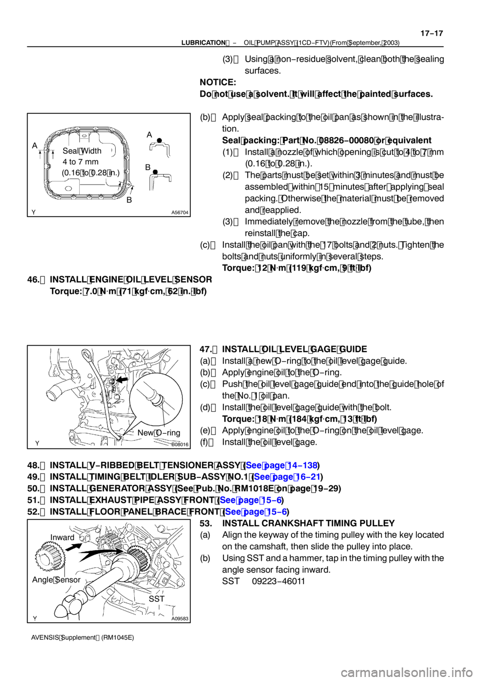
(b) Apply seal packing to the oil pan as shown in the illustra- tion.
Seal packing: Part No. 08826 −00080 or equivalent
(1) Install a nozzle of which opening is cut to 4 to 7 mm (0.16 to 0.28 in.).
(2) The parts must be set within 3 minutes and must be assembled within 15 minutes after applying seal
packing. Otherwise the material must be removed
and reapplied.
(3) Immediately remove the nozzle from the tube, then
reinstall the cap.
(c) Install the oil pan with the 17 bolts and 2 nuts. Tighten the
bolts and nuts uniformly in several steps.
Torque: 12 N �m (119 kgf �cm, 9 ft �lbf)
46. INSTALL ENGINE OIL LEVEL SENSOR Torque: 7.0 N �m (71 kgf �cm, 62 in. �lbf)
47. INSTALL OIL LEVEL GAGE GUIDE
(a) Install a new O −ring to the oil level gage guide.
(b) Apply engine oil to the O −ring.
(c) Push the oil level gage guide end into the guide hole of the No. 1 oil pan.
(d) Install the oil level gage guide with the bolt. Torque: 18 N �m (184 kgf �cm, 13 ft �lbf)
(e) Apply engine oil to the O −ring on the oil level gage.
(f) Install the oil level gage.
48. INSTALL V −RIBBED BELT TENSIONER ASSY (See page 14 −138)
49. INSTALL TIMING BELT IDLER SUB −ASSY NO.1 (See page 16 −21)
50. INSTALL GENERATOR ASSY (See Pub. No. RM1018E on page 19 −29)
51. INSTALL EXHAUST PIPE ASSY FRONT (See page 15 −6)
52. INSTALL FLOOR PANEL BRACE FRONT (See page 15 −6)
53. INSTALL CRANKSHAFT TIMING PULLEY
(a) Align the keyway of the timing pulley with the key located on the camshaft, then slide the pulley into place.
(b) Using SST and a hammer, tap in the timing pulley with the
angle sensor facing inward.
SST 09223 −46011
Page 4759 of 5135

160MR−02
B12054
SST
B12052
B12053
Pry
PryPry
16
−12
−
COOLING WATER PUMP ASSY (2AZ −FSE)
AVENSIS Supplement (RM1045E)
WATER PUMP ASSY (2AZ −FSE)
REPLACEMENT
1. DRAIN COOLANT (See page 16 −7)
2. REMOVE RADIATOR SUPPORT OPENING COVER (See page 14 −23)
3. REMOVE ENGINE ROOM COVER SIDE (See page 14 −23)
4. REMOVE ENGINE UNDER COVER LH (See page 14 −23)
5. REMOVE ENGINE UNDER COVER NO.4 RH (See page 14 −23)
6. REMOVE ENGINE UNDER COVER RH (See page 14 −23)
7. REMOVE FAN AND GENERATOR V BELT (See page 14 −5)
SST 09249 −63010
8. REMOVE GENERATOR ASSY (See page 19 −8)
9. REMOVE WATER PUMP PULLEY
(a) Using SST, remove the 4 bolts and pump pulley. SST 09960 −10010 (09962 −01000, 09963 −00700)
(b) Disconnect the crankshaft position sensor wire clamp
from the water pump.
(c) Disconnect the crankshaft position sensor wire from the clamp on the water pump.
10. REMOVE WATER PUMP ASSY
(a) Remove the 4 bolts, 2 nuts, wire clamp and water pump.
(b) Using a screwdriver, pry out between the water pump and cylinder block, and remove the water pump.
NOTICE:
Be careful not to damage the contact surface of the water
pump and cylinder block.