Page 2776 of 3171
![NISSAN NAVARA 2005 Repair Workshop Manual TROUBLE DIAGNOSIS FOR SYMPTOMS
RFD-73
[WITH ELECTRONIC LOCKING DIFFERENTIAL]
C
E
F
G
H
I
J
K
L
MA
B
RFD
DIFF LOCK Indicator Lamp Does Not ChangeEDS003BA
SYMPTOM:
DIFF LOCK indicator lamp does not chan NISSAN NAVARA 2005 Repair Workshop Manual TROUBLE DIAGNOSIS FOR SYMPTOMS
RFD-73
[WITH ELECTRONIC LOCKING DIFFERENTIAL]
C
E
F
G
H
I
J
K
L
MA
B
RFD
DIFF LOCK Indicator Lamp Does Not ChangeEDS003BA
SYMPTOM:
DIFF LOCK indicator lamp does not chan](/manual-img/5/57362/w960_57362-2775.png)
TROUBLE DIAGNOSIS FOR SYMPTOMS
RFD-73
[WITH ELECTRONIC LOCKING DIFFERENTIAL]
C
E
F
G
H
I
J
K
L
MA
B
RFD
DIFF LOCK Indicator Lamp Does Not ChangeEDS003BA
SYMPTOM:
DIFF LOCK indicator lamp does not change when turning differential lock mode switch to “ON” after
engine start.
DIAGNOSTIC PROCEDURE
1.CHECK DIFF LOCK INDICATOR LAMP
Confirm DIFF LOCK indicator lamp when ignition switch is turned to ON.
Does DIFF LOCK indicator lamp turn on?
YES >> GO TO 2.
NO >> Go toRFD-70, "
DIFF LOCK Indicator Lamp Does Not Turn ON".
2.CHECK SELF-DIAGNOSTIC RESULTS
Perform self-diagnosis. Refer toRFD-51, "
SELF-DIAG RESULTS MODE".
Is any malfunction detected by self-diagnosis?
YES >> Check the malfunctioning system.
NO >> GO TO 3.
3.CHECK SYSTEM FOR DIFFERENTIAL LOCK MODE SWITCH
Perform trouble diagnosis for differential lock mode switch system. Refer toRFD-56, "
Differential Lock Mode
Switch".
OK or NG
OK >> GO TO 4.
NG >> Repair or replace damaged parts.
4.CHECK SYMPTOM
Check again.
OK or NG
OK >>INSPECTION END
NG >> GO TO 5.
5.CHECK DIFFERENTIAL LOCK CONTROL UNIT
Check differential lock control unit input/output signal. Refer toRFD-48, "
Differential Lock Control Unit Input/
Output Signal Reference Values".
OK or NG
OK >>INSPECTION END
NG >> Check differential lock control unit pin terminals for damage or loose connection with harness con-
nector. If any items are damaged, repair or replace damaged parts.
Page 2807 of 3171
RSU-2
PRECAUTIONS
PRECAUTIONS
PFP:00001
PrecautionsEES002JD
lWhen installing rubber parts, final tightening must be carried out under unladen condition* with
tires on ground.
*Fuel, radiator coolant, and engine oil are full. Spare tire, jack, hand tools, and mats are in their
designated positions. Oil will shorten the life of rubber bushings, so wipe off any spilled oil imme-
diately.
lLock nuts are not reusable. Always use new lock nuts for installation. New lock nuts are pre-oiled,
do not apply any additional lubrication.
Page 2810 of 3171

REAR SUSPENSION ASSEMBLY
RSU-5
C
D
F
G
H
I
J
K
L
MA
B
RSU
CAUTION:
When installing the components with rubber bushings, the final tightening of the nuts and bolts must
be done with the vehicle in an unladen condition (the fuel, engine coolant, and engine oil full; the
spare tire, jack, hand tools and mats in their designated positions) with the tires on the ground.
On-Vehicle Inspection and ServiceEES002JH
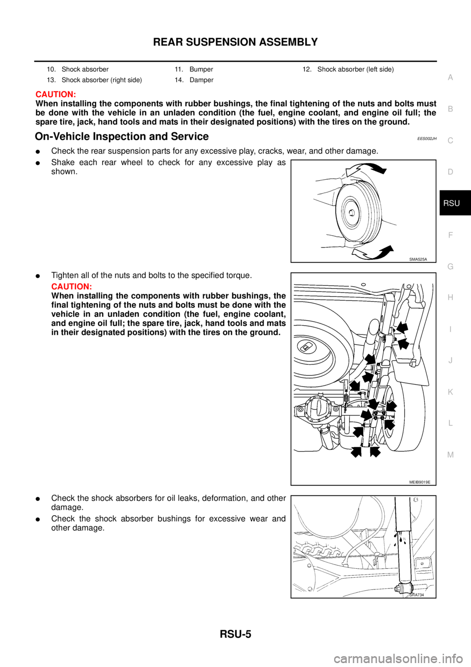
lCheck the rear suspension parts for any excessive play, cracks, wear, and other damage.
lShake each rear wheel to check for any excessive play as
shown.
lTighten all of the nuts and bolts to the specified torque.
CAUTION:
When installing the components with rubber bushings, the
final tightening of the nuts and bolts must be done with the
vehicle in an unladen condition (the fuel, engine coolant,
and engine oil full; the spare tire, jack, hand tools and mats
in their designated positions) with the tires on the ground.
lCheck the shock absorbers for oil leaks, deformation, and other
damage.
lCheck the shock absorber bushings for excessive wear and
other damage.
10. Shock absorber 11. Bumper 12. Shock absorber (left side)
13. Shock absorber (right side) 14. Damper
SMA525A
MEIB9019E
SRA734
Page 2813 of 3171
RSU-8
LEAF SPRING
CAUTION:
When installing the components with rubber bushings, the final tightening of the nuts and bolts must
be done with the vehicle in an unladen condition (the fuel, engine coolant, and engine oil full; the
spare tire, jack, hand tools and mats in their designated positions) with the tires on the ground.
REMOVAL
1. Support the rear final drive assembly with a suitable jack to relieve the tension from the rear leaf spring.
lThe axle weight should be supported, but there should be no compression in the rear leaf spring.
2. Remove the shock absorber lower nut and bolt.
3. Remove the four rear spring clip U-bolt nuts, then remove the
rear spring pad.
4. Remove the rear spring shackle and bushings.
5. Remove the rear leaf spring front nut and bolt.
6. Remove the rear leaf spring.
10. Shock absorber 11. Bumper 12. Shock absorber (left side)
13. Shock absorber (right side) 14. Damper
LEIA0115E
LEIA0106E
LEIA0116E
LEIA0107E
Page 2815 of 3171
RSU-10
LEAF SPRING
8. Tighten the rear spring shackle nuts, rear leaf spring front nut,
and shock absorber nuts to specification.
lWhen installing the components with rubber bushings, the
final nut tightening must be carried out under unladen* condi-
tions with the tires on level ground.
* (Fuel, radiator coolant and engine oil full. Spare tire, jack,
hand tools and mats in designated positions.)
SRA754
Page 2816 of 3171

SERVICE DATA AND SPECIFICATIONS (SDS)
RSU-11
C
D
F
G
H
I
J
K
L
MA
B
RSU
SERVICE DATA AND SPECIFICATIONS (SDS)PFP:00030
General Specifications (Rear)EES002JK
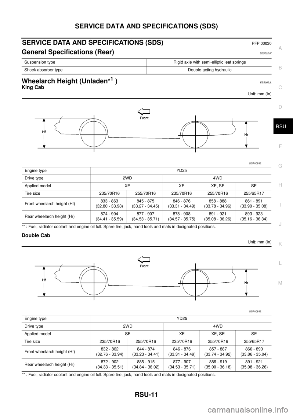
Wheelarch Height (Unladen*1)EES002JL
King Cab
Unit: mm (in)
*1: Fuel, radiator coolant and engine oil full. Spare tire, jack, hand tools and mats in designated positions.
Double Cab
Unit: mm (in)
*1: Fuel, radiator coolant and engine oil full. Spare tire, jack, hand tools and mats in designated positions.Suspension type Rigid axle with semi-elliptic leaf springs
Shock absorber type Double-acting hydraulic
Engine type YD25
Drive type 2WD 4WD
Applied model XE XE XE, SE SE
Tire size 235/70R16 255/70R16 235/70R16 255/70R16 255/65R17
Front wheelarch height (Hf)833 - 863
(32.80 - 33.98)845 - 875
(33.27 - 34.45)846 - 876
(33.31 - 34.49)858 - 888
(33.78 - 34.96)861 - 891
(33.90 - 35.08)
Rear wheelarch height (Hr)874 - 904
(34.41 - 35.59)877 - 907
(34.53 - 35.71)878 - 908
(34.57 - 35.75)891 - 921
(35.08 - 36.26)893 - 923
(35.16 - 36.34)
LEIA0085E
Engine type YD25
Drive type 2WD 4WD
Applied model SE XE XE, SE SE
Tire size 235/70R16 255/70R16 235/70R16 255/70R16 255/65R17
Front wheelarch height (Hf)832 - 862
(32.76 - 33.94)844 - 874
(33.23 - 34.41)846 - 876
(33.31 - 34.49)857 - 887
(33.74 - 34.92)860 - 890
(33.86 - 35.04)
Rear wheelarch height (Hr)872 - 902
(34.33 - 35.51)885 - 915
(34.84 - 36.02)877 - 907
(34.53 - 35.71)889 - 919
(35.00 - 36.18)891 - 921
(35.08 - 36.26)
LEIA0085E
Page 2838 of 3171

BATTERY
SC-5
C
D
E
F
G
H
I
J
L
MA
B
SC
BATTERYPFP:00011
How to Handle BatteryEKS00MZ7
CAUTION:
lIf it becomes necessary to start the engine with a booster battery and jumper cables, use a 12-volt
booster battery.
lAfter connecting battery cables, ensure that they are tightly clamped to battery terminals for good
contact.
lNever add distilled water through the hole used to check specific gravity.
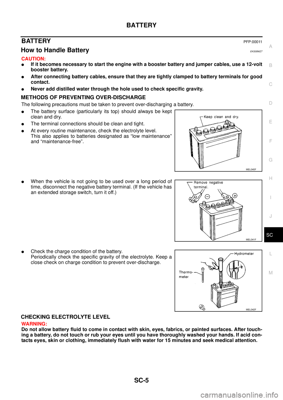
METHODS OF PREVENTING OVER-DISCHARGE
The following precautions must be taken to prevent over-discharging a battery.
lThe battery surface (particularly its top) should always be kept
clean and dry.
lThe terminal connections should be clean and tight.
lAt every routine maintenance, check the electrolyte level.
This also applies to batteries designated as “low maintenance”
and “maintenance-free”.
lWhen the vehicle is not going to be used over a long period of
time, disconnect the negative battery terminal. (If the vehicle has
an extended storage switch, turn it off.)
lCheck the charge condition of the battery.
Periodically check the specific gravity of the electrolyte. Keep a
close check on charge condition to prevent over-discharge.
CHECKING ELECTROLYTE LEVEL
WARNING:
Do not allow battery fluid to come in contact with skin, eyes, fabrics, or painted surfaces. After touch-
ing a battery, do not touch or rub your eyes until you have thoroughly washed your hands. If acid con-
tacts eyes, skin or clothing, immediately flush with water for 15 minutes and seek medical attention.
MEL040F
MEL041F
MEL042F
Page 2847 of 3171

SC-14
CHARGING SYSTEM
CHARGING SYSTEM
PFP:00011
System DescriptionEKS00MZA
The alternator provides DC voltage to operate the vehicle's electrical system and to keep the battery charged.
The voltage output is controlled by the IC regulator.
Power is supplied at all times to alternator terminal 4 through:
l15A fuse (No. 30, located in the fuse and fusible link box).
Terminal 1 supplies power to charge the battery and operate the vehicle's electrical system. Output voltage is
controlled by the IC regulator at terminal 4 detecting the input voltage. The charging circuit is protected by the
140A fusible link (letter "A", located in the fuse and fusible link box) .
The alternator is grounded to the engine block.
With the ignition switch in the ON or START position, power is supplied
l10A fuse [No. 14, located in the fuse block (J/B)]
lto combination meter terminal 16 for the charge warning lamp.
Ground is supplied With power and ground supplied
lto terminal 2 of the combination meter
lthrough terminal 3 of the alternator.
If the charge warning lamp illuminates with the engine running, a fault is indicated.
The charge warning lamp will illuminate. When the alternator is providing sufficient voltage with the engine
running, the ground is opened and the charge warning lamp will go off.