Page 2600 of 3171
ELECTRICAL UNITS LOCATION
PG-71
C
D
E
F
G
H
I
J
L
MA
B
PG
ELECTRICAL UNITS LOCATIONPFP:25230
Electrical Units LocationEKS00LJA
ENGINE COMPARTMENT
MKWA3887E
Page 2633 of 3171

PS-6
POWER STEERING FLUID
POWER STEERING FLUID
PFP:KLF20
Checking Fluid LevelEGS001LD
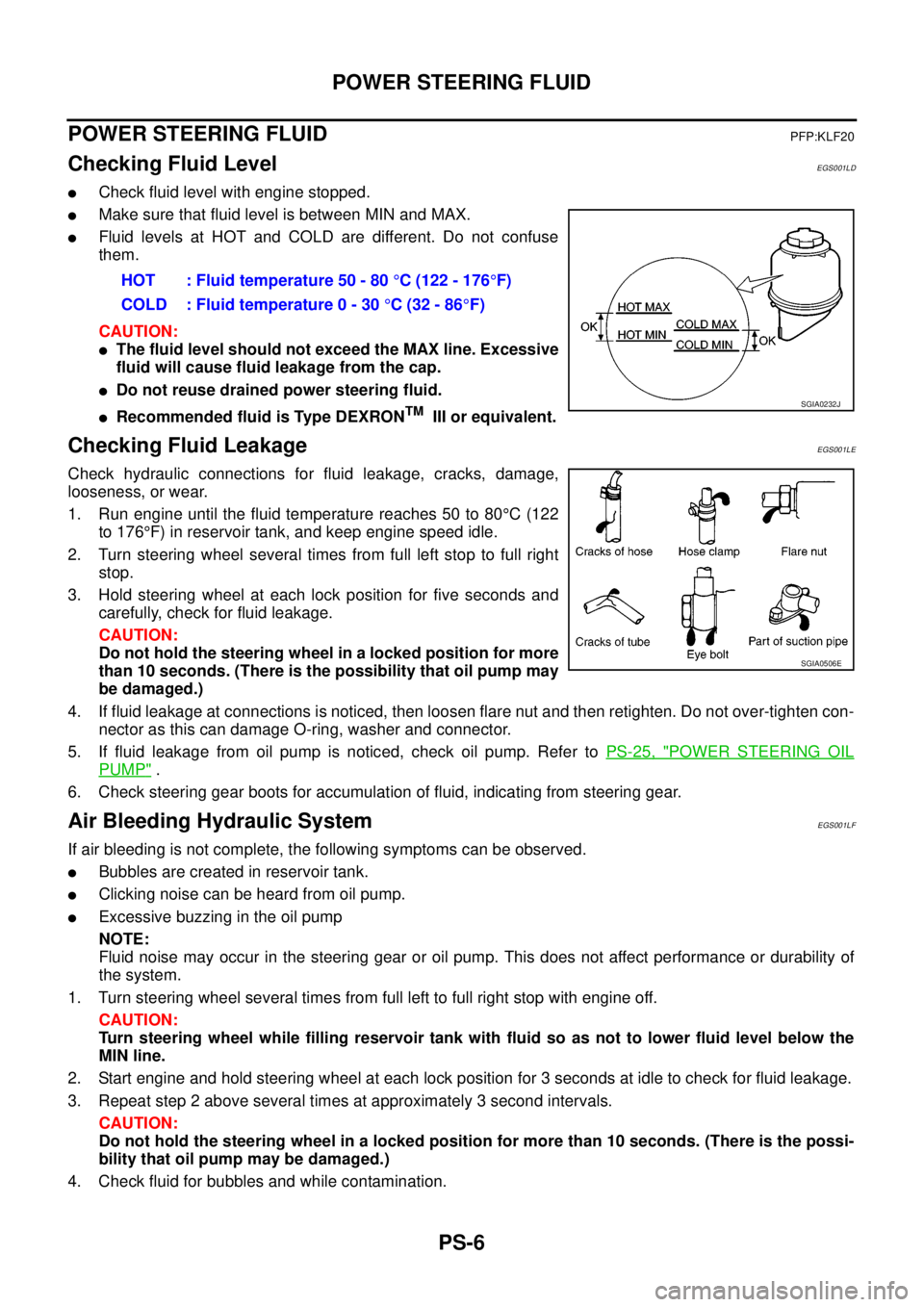
lCheck fluid level with engine stopped.
lMake sure that fluid level is between MIN and MAX.
lFluid levels at HOT and COLD are different. Do not confuse
them.
CAUTION:
lThe fluid level should not exceed the MAX line. Excessive
fluid will cause fluid leakage from the cap.
lDo not reuse drained power steering fluid.
lRecommended fluid is Type DEXRONTMIII or equivalent.
Checking Fluid LeakageEGS001LE
Check hydraulic connections for fluid leakage, cracks, damage,
looseness, or wear.
1. Run engine until the fluid temperature reaches 50 to 80°C(122
to 176°F) in reservoir tank, and keep engine speed idle.
2. Turn steering wheel several times from full left stop to full right
stop.
3. Hold steering wheel at each lock position for five seconds and
carefully, check for fluid leakage.
CAUTION:
Do not hold the steering wheel in a locked position for more
than 10 seconds. (There is the possibility that oil pump may
be damaged.)
4. If fluid leakage at connections is noticed, then loosen flare nut and then retighten. Do not over-tighten con-
nector as this can damage O-ring, washer and connector.
5. If fluid leakage from oil pump is noticed, check oil pump. Refer toPS-25, "
POWER STEERING OIL
PUMP".
6. Check steering gear boots for accumulation of fluid, indicating from steering gear.
Air Bleeding Hydraulic SystemEGS001LF
If air bleeding is not complete, the following symptoms can be observed.
lBubbles are created in reservoir tank.
lClicking noise can be heard from oil pump.
lExcessive buzzing in the oil pump
NOTE:
Fluid noise may occur in the steering gear or oil pump. This does not affect performance or durability of
the system.
1. Turn steering wheel several times from full left to full right stop with engine off.
CAUTION:
Turn steering wheel while filling reservoir tank with fluid so as not to lower fluid level below the
MIN line.
2. Start engine and hold steering wheel at each lock position for 3 seconds at idle to check for fluid leakage.
3. Repeat step 2 above several times at approximately 3 second intervals.
CAUTION:
Do not hold the steering wheel in a locked position for more than 10 seconds. (There is the possi-
bility that oil pump may be damaged.)
4. Check fluid for bubbles and while contamination.HOT : Fluid temperature 50 - 80°C (122 - 176°F)
COLD : Fluid temperature 0 - 30°C(32-86°F)
SGIA0232J
SGIA0506E
Page 2634 of 3171
POWER STEERING FLUID
PS-7
C
D
E
F
H
I
J
K
L
MA
B
PS
5. Stop engine if bubbles and white contamination do not drain out. Perform step 2 and 3 above after waiting
until bubbles and white contamination drain out.
6. Stop the engine, and then check fluid level.
Page 2635 of 3171

PS-8
STEERING WHEEL
STEERING WHEEL
PFP:48430
On-Vehicle Inspection and ServiceEGS001LG
CHECKING CONDITION OF INSTALLATION
lCheck installation conditions of steering gear assembly, front suspension assembly, axle and steering col-
umn assembly.
lCheck if movement exists when steering wheel is moved up and down, to the left and right and to the axial
direction.
lCheck steering gear assembly mounting bolts and nuts for looseness. Refer toPS-14, "COMPONENT".
CHECKING STEERING WHEEL PLAY
lTurn steering wheel so that front wheels come to the straight-ahead position. Start engine and lightly turn
steering wheel to the left and right until front wheels start to move. Measure steering wheel movement on
the outer circumference.
lWhen the measurement value is outside the standard value, check backlash for each joint of steering col-
umn assembly and installation condition of steering gear assembly.
CHECKING NEUTRAL POSITION STEERING WHEEL
lMake sure that steering gear assembly, steering column assembly and steering wheel are installed in the
correct position.
lPerform neutral position inspection after wheel alignment. Refer toFSU-7, "Front Wheel Alignment".
lSet vehicle to the straight-ahead position and confirm steering wheel is in the neutral position.
lLoosen outer socket lock nut and turn inner socket to left and right equally to make fine adjustment if
steering wheel is not in the neutral position.
CHECKING STEERING WHEEL TURNING FORCE
1. Park vehicle on a level and dry surface, set parking brake.
2. Start engine.
3. Bring power steering fluid up to adequate operating temperature. [Make sure temperature of fluid is
approximately 50 to 80°C(122to176°F).]
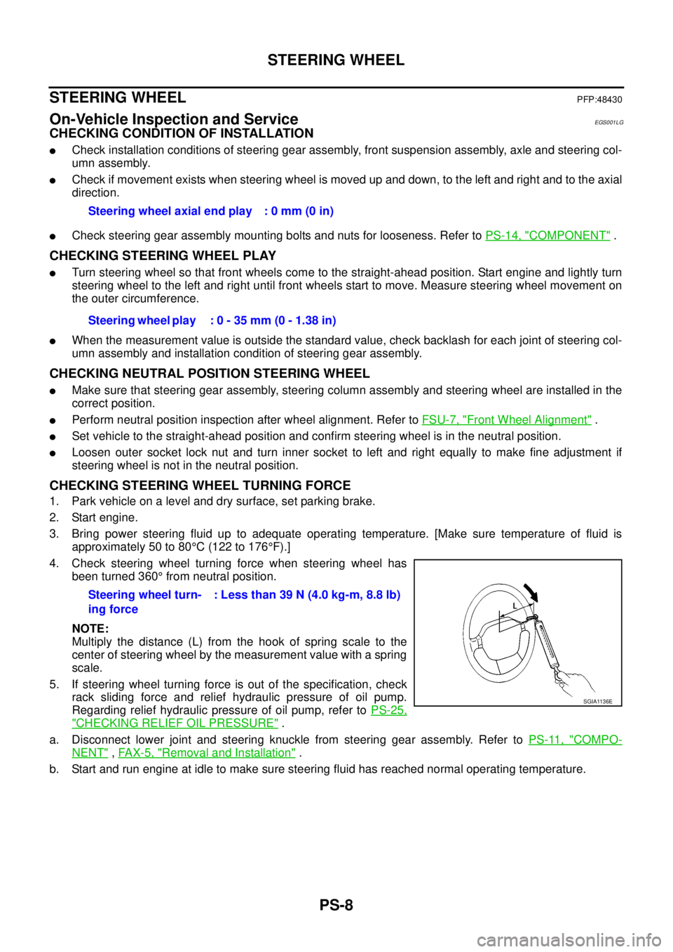
4. Check steering wheel turning force when steering wheel has
been turned 360°from neutral position.
NOTE:
Multiply the distance (L) from the hook of spring scale to the
center of steering wheel by the measurement value with a spring
scale.
5. If steering wheel turning force is out of the specification, check
rack sliding force and relief hydraulic pressure of oil pump.
Regarding relief hydraulic pressure of oil pump, refer toPS-25,
"CHECKING RELIEF OIL PRESSURE".
a. Disconnect lower joint and steering knuckle from steering gear assembly. Refer toPS-11, "
COMPO-
NENT",FAX-5, "Removal and Installation".
b. Start and run engine at idle to make sure steering fluid has reached normal operating temperature.Steering wheel axial end play : 0 mm (0 in)
Steering wheel play : 0 - 35 mm (0 - 1.38 in)
Steering wheel turn-
ing force: Less than 39 N (4.0 kg-m, 8.8 lb)
SGIA1136E
Page 2636 of 3171

STEERING WHEEL
PS-9
C
D
E
F
H
I
J
K
L
MA
B
PS
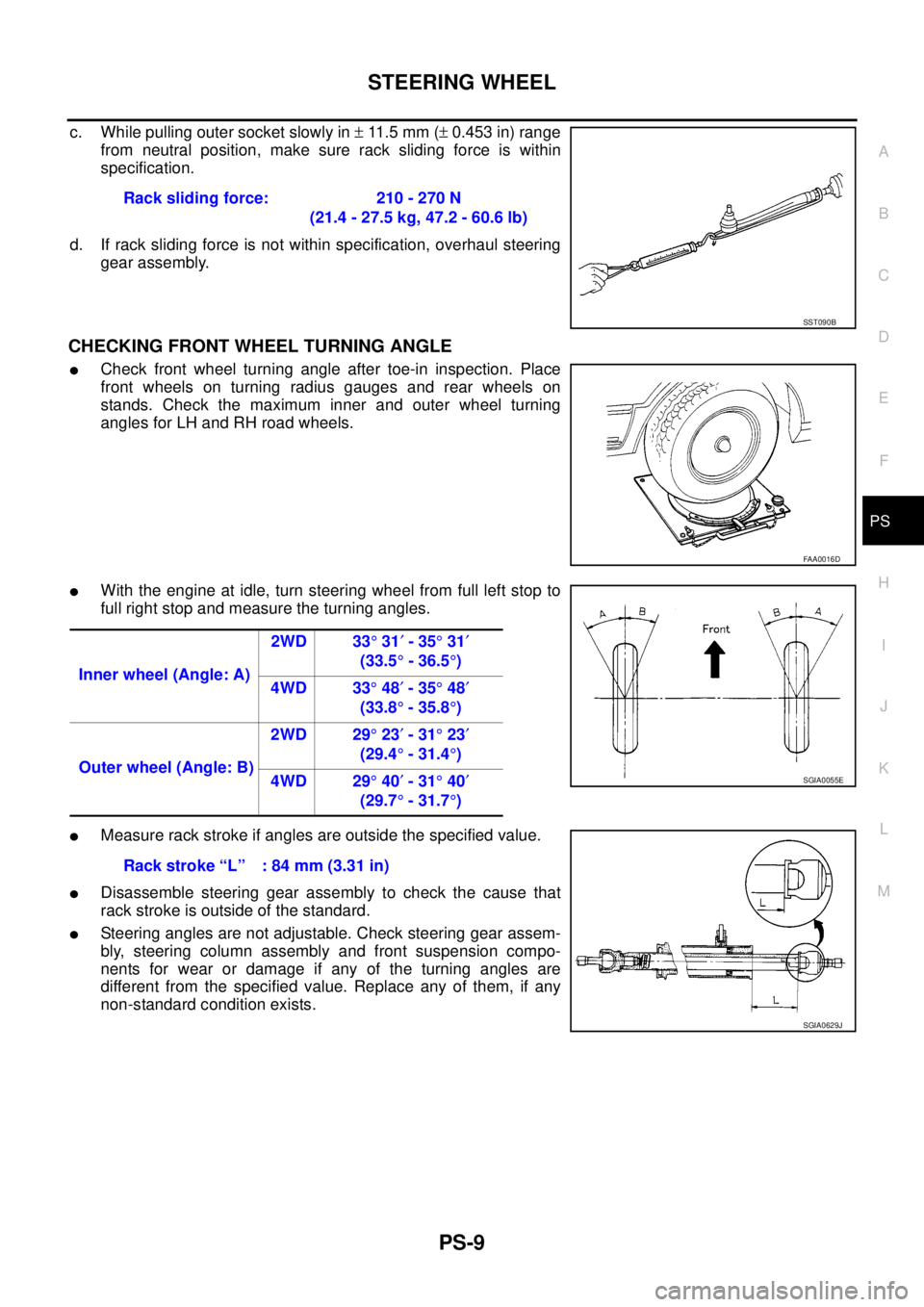
c. While pulling outer socket slowly in±11 . 5 m m (±0.453 in) range
from neutral position, make sure rack sliding force is within
specification.
d. If rack sliding force is not within specification, overhaul steering
gear assembly.
CHECKING FRONT WHEEL TURNING ANGLE
lCheck front wheel turning angle after toe-in inspection. Place
front wheels on turning radius gauges and rear wheels on
stands. Check the maximum inner and outer wheel turning
angles for LH and RH road wheels.
lWith the engine at idle, turn steering wheel from full left stop to
full right stop and measure the turning angles.
lMeasure rack stroke if angles are outside the specified value.
lDisassemble steering gear assembly to check the cause that
rack stroke is outside of the standard.
lSteering angles are not adjustable. Check steering gear assem-
bly, steering column assembly and front suspension compo-
nents for wear or damage if any of the turning angles are
different from the specified value. Replace any of them, if any
non-standard condition exists.Rack sliding force: 210 - 270 N
(21.4 - 27.5 kg, 47.2 - 60.6 lb)
SST090B
FAA0016D
Inner wheel (Angle: A)2WD 33°31¢-35°31¢
(33.5°-36.5°)
4WD 33°48¢-35°48¢
(33.8°-35.8°)
Outer wheel (Angle: B)2WD 29°23¢-31°23¢
(29.4°-31.4°)
4WD 29°40¢-31°40¢
(29.7°-31.7°)
SGIA0055E
Rack stroke “L” : 84 mm (3.31 in)
SGIA0629J
Page 2652 of 3171

POWER STEERING OIL PUMP
PS-25
C
D
E
F
H
I
J
K
L
MA
B
PS
POWER STEERING OIL PUMPPFP:49110
On-Vehicle Inspection and ServiceEGS001LL
CHECKING RELIEF OIL PRESSURE
CAUTION:
Make sure that belt tension is normal before starting the following procedure.
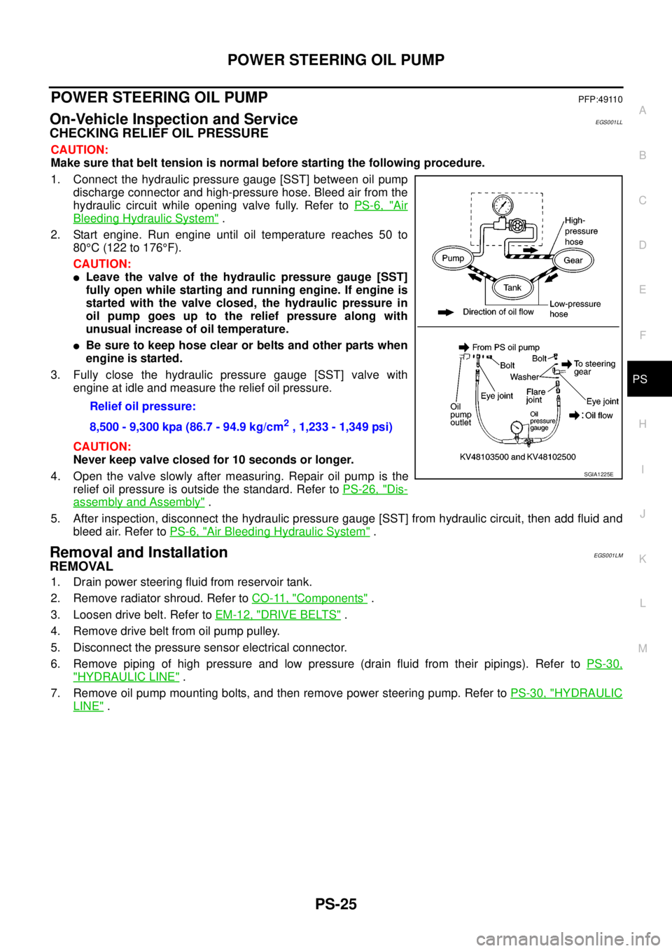
1. Connect the hydraulic pressure gauge [SST] between oil pump
discharge connector and high-pressure hose. Bleed air from the
hydraulic circuit while opening valve fully. Refer toPS-6, "
Air
Bleeding Hydraulic System".
2. Start engine. Run engine until oil temperature reaches 50 to
80°C(122to176°F).
CAUTION:
lLeave the valve of the hydraulic pressure gauge [SST]
fully open while starting and running engine. If engine is
started with the valve closed, the hydraulic pressure in
oil pump goes up to the relief pressure along with
unusual increase of oil temperature.
lBe sure to keep hose clear or belts and other parts when
engineisstarted.
3. Fully close the hydraulic pressure gauge [SST] valve with
engine at idle and measure the relief oil pressure.
CAUTION:
Never keep valve closed for 10 seconds or longer.
4. Open the valve slowly after measuring. Repair oil pump is the
relief oil pressure is outside the standard. Refer toPS-26, "
Dis-
assembly and Assembly".
5. After inspection, disconnect the hydraulic pressure gauge [SST] from hydraulic circuit, then add fluid and
bleed air. Refer toPS-6, "
Air Bleeding Hydraulic System".
Removal and InstallationEGS001LM
REMOVAL
1. Drain power steering fluid from reservoir tank.
2. Remove radiator shroud. Refer toCO-11, "
Components".
3. Loosen drive belt. Refer toEM-12, "
DRIVE BELTS".
4. Remove drive belt from oil pump pulley.
5. Disconnect the pressure sensor electrical connector.
6. Remove piping of high pressure and low pressure (drain fluid from their pipings). Refer toPS-30,
"HYDRAULIC LINE".
7. Remove oil pump mounting bolts, and then remove power steering pump. Refer toPS-30, "
HYDRAULIC
LINE". Relief oil pressure:
8,500 - 9,300 kpa (86.7 - 94.9 kg/cm
2, 1,233 - 1,349 psi)
SGIA1225E
Page 2665 of 3171
RAX-2
[M226]
PRECAUTIONS
[M226]PRECAUTIONSPFP:00001
PrecautionsEDS003HT
lWhen installing the rubber bushings, the final tightening must be done under unladen condition and with
the tires on level ground. Oil will shorten the life of the rubber bushings, so wipe off any spilled oil immedi-
ately.
lUnladen condition means the fuel tank, engine coolant and lubricants are at the full secification. The
spare tire, jack, hand tools, and mats are in their designated positions.
lLock nuts are not reusable. Always use new lock nuts for installation. New lock nuts are pre-oiled, do not
apply any additional lubrication.
Page 2680 of 3171
PREPARATION
RF-3
C
D
E
F
G
H
J
K
L
MA
B
RF
PREPARATIONPFP:00002
Commercial Service ToolEIS00B94
Tool nameDescription
Engine earLocating the noise
SIIA0995E