Page 2547 of 3171

PG-18
IPDM E/R (INTELLIGENT POWER DISTRIBUTION MODULE ENGINE ROOM)
5. Touch “RECORD” while monitoring to record the status of the item being monitored. To stop recording,
touch “STOP”.
All Signals, Main Signals, Selection From Menu
NOTE:
Perform monitoring of IPDM E/R data with the ignition switch ON. When the ignition switch is in ACC position,
display may not be correct.
CAN DIAG SUPPORT MNTR
Refer toLAN-15, "CAN Diagnostic Support Monitor".
ACTIVE TEST
Operation Procedure
1. Touch “ACTIVE TEST” on “SELECT DIAG-MODE” screen.
2. Touch item to be tested, and check operation.
3. Touch “START”.
4. Touch “STOP” while testing to stop the operation.
Item nameCONSULT-II
screen displayDisplay or unitMonitor item selection
Description
ALL
SIGNALSMAIN
SIGNALSSELECTION
FROM MENU
Motor fan requestMOTOR FAN
REQ1/2/3/4 X X X Signal status input from ECM
A/C compressor
requestAC COMP REQ ON/OFF X X X Signal status input from ECM
Tail & clear
requestTAIL & CLR REQ ON/OFF X X X Signal status input from BCM
Headlamp LO
requestHL LO REQ ON/OFF X X X Signal status input from BCM
Headlamp HI
requestHL HI REQ ON/OFF X X X Signal status input from BCM
Front fog lamp
requestFR FOG REQ ON/OFF X X X Signal status input from BCM
Headlamp washer
requestHL WASHER
REQON/OFF X X Signal from input from BCM
Front wiper
requestFR WIP REQSTOP/1LOW/
LOW/HIX X X Signal status input from BCM
Wiper auto stopWIP AUTO
STOPACT P/STOP P X X X Output status of IPDM E/R
Wiper protection WIP PROT OFF/BLOCK X X X Control status of IPDM E/R
Starter request ST RLY REQ ON/OFF X X
Status of input signal
NOTE
Ignition relay
statusIGN RLY ON/OFF X X XIgnition relay status monitored
with IPDM E/R
Rear defogger
requestRR DEF REQ ON/OFF X X X Signal status input from BCM
Oil pressure
switchOIL P SW OPEN/CLOSE X XSignal status input from IPDM
E/R
Hood switch HOOD SW OFF XSignal status input from IPDM
E/R (function is not enabled)
Theft warning
horn requestTHFT HRN REQ ON/OFF X X Signal status input from BCM
Horn chirp HORN CHIRP ON/OFF X X Output status of IPDM E/R
Page 2548 of 3171

IPDM E/R (INTELLIGENT POWER DISTRIBUTION MODULE ENGINE ROOM)
PG-19
C
D
E
F
G
H
I
J
L
MA
B
PG
Auto Active TestEKS00PAC
DESCRIPTION
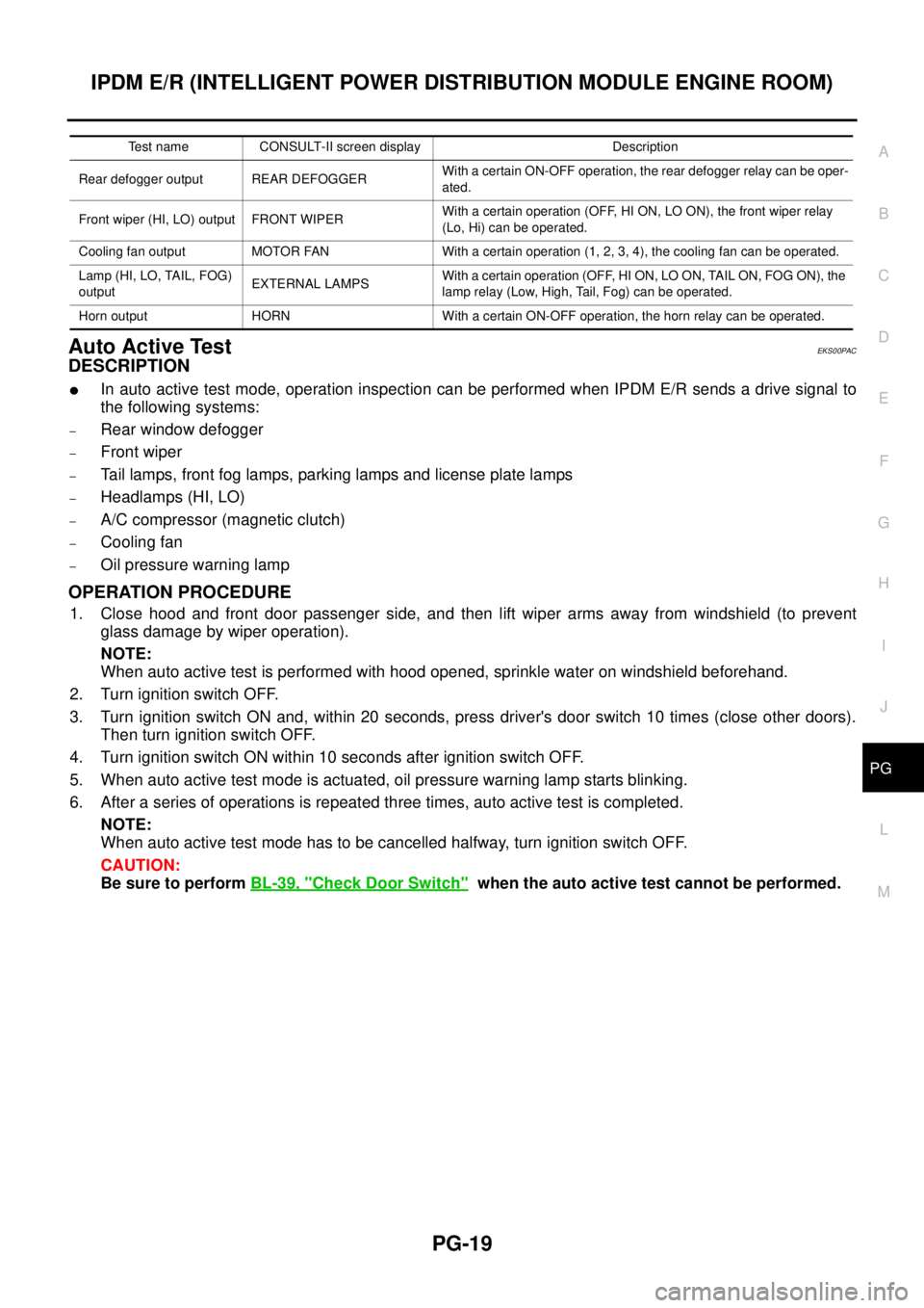
lIn auto active test mode, operation inspection can be performed when IPDM E/R sends a drive signal to
the following systems:
–Rear window defogger
–Front wiper
–Tail lamps, front fog lamps, parking lamps and license plate lamps
–Headlamps (HI, LO)
–A/C compressor (magnetic clutch)
–Cooling fan
–Oil pressure warning lamp
OPERATION PROCEDURE
1. Close hood and front door passenger side, and then lift wiper arms away from windshield (to prevent
glass damage by wiper operation).
NOTE:
When auto active test is performed with hood opened, sprinkle water on windshield beforehand.
2. Turn ignition switch OFF.
3. Turn ignition switch ON and, within 20 seconds, press driver's door switch 10 times (close other doors).
Then turn ignition switch OFF.
4. Turn ignition switch ON within 10 seconds after ignition switch OFF.
5. When auto active test mode is actuated, oil pressure warning lamp starts blinking.
6. After a series of operations is repeated three times, auto active test is completed.
NOTE:
When auto active test mode has to be cancelled halfway, turn ignition switch OFF.
CAUTION:
Be sure to performBL-39, "
Check Door Switch"when the auto active test cannot be performed.
Test name CONSULT-II screen display Description
Rear defogger output REAR DEFOGGERWith a certain ON-OFF operation, the rear defogger relay can be oper-
ated.
Front wiper (HI, LO) output FRONT WIPERWith a certain operation (OFF, HI ON, LO ON), the front wiper relay
(Lo, Hi) can be operated.
Cooling fan output MOTOR FAN With a certain operation (1, 2, 3, 4), the cooling fan can be operated.
Lamp (HI, LO, TAIL, FOG)
outputEXTERNAL LAMPSWith a certain operation (OFF, HI ON, LO ON, TAIL ON, FOG ON), the
lamp relay (Low, High, Tail, Fog) can be operated.
Horn output HORN With a certain ON-OFF operation, the horn relay can be operated.
Page 2549 of 3171

PG-20
IPDM E/R (INTELLIGENT POWER DISTRIBUTION MODULE ENGINE ROOM)
INSPECTION IN AUTO ACTIVE TEST MODE
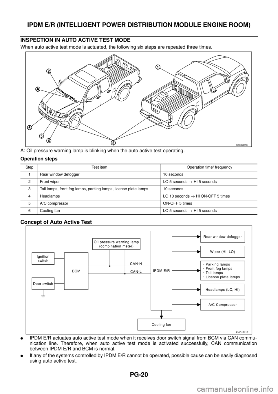
When auto active test mode is actuated, the following six steps are repeated three times.
A: Oil pressure warning lamp is blinking when the auto active test operating.
Operation steps
Concept of Auto Active Test
lIPDM E/R actuates auto active test mode when it receives door switch signal from BCM via CAN commu-
nication line. Therefore, when auto active test mode is activated successfully, CAN communication
between IPDM E/R and BCM is normal.
lIf any of the systems controlled by IPDM E/R cannot be operated, possible cause can be easily diagnosed
using auto active test.
SKIB6851E
Step Test item Operation time/ frequency
1 Rear window defogger 10 seconds
2 Front wiper LO 5 seconds®HI 5 seconds
3 Tail lamps, front fog lamps, parking lamps, license plate lamps 10 seconds
4 Headlamps LO 10 seconds®HI ON-OFF 5 times
5 A/C compressor ON-OFF 5 times
6 Cooling fan LO 5 seconds®HI 5 seconds
PKIC1721E
Page 2550 of 3171

IPDM E/R (INTELLIGENT POWER DISTRIBUTION MODULE ENGINE ROOM)
PG-21
C
D
E
F
G
H
I
J
L
MA
B
PG
Diagnosis chart in auto active test mode
Symptom Inspection contents Possible cause
Any of front wipers, tail
and parking lamps, front
fog lamps, and
headlamps (HI, LO) do
not operate.Perform auto active
test. Does system in
question operate?YES
lBCM signal input system malfunction
NO
lLamp/wiper motor malfunction
lLamp/wiper motor ground circuit malfunction
lHarness/connector malfunction between IPDM E/R and system in
question
lIPDM E/R (integrated relay) malfunction
Rear window defogger
does not operate.Perform auto active
test. Does rear win-
dow defogger oper-
ate?YES
lBCM signal input circuit malfunction
NO
lRear window defogger relay malfunction
lOpen circuit of rear window defogger
lHarness or connector malfunction between IPDM E/R and rear window
defogger
lIPDM E/R (integrated relay) malfunction
A/C compressor does
not operate.Perform auto active
test. Does magnetic
clutch operate?YES
lBCM signal input circuit malfunction
lCAN communication signal malfunction between BCM and ECM
lCAN communication signal malfunction between ECM and IPDM E/R
NO
lMagnetic clutch malfunction
lHarness/connector malfunction between IPDM E/R and magnetic
clutch
lIPDM E/R (integrated relay) malfunction
Cooling fan does not
operate.Perform auto active
test. Does cooling fan
operate?YES
lECM signal input circuit malfunction
lCAN communication signal malfunction between ECM and IPDM E/R
NO
lCooling fan motor malfunction
lHarness/connector malfunction between IPDM E/R and cooling fan
motor
lIPDM E/R (integrated relay) malfunction
Oil pressure warning
lamp does not operate.Perform auto active
test. Does oil pres-
sure warning lamp
blink?YES
lHarness/connector malfunction between IPDM E/R and oil pressure
switch
lOil pressure switch malfunction
lIPDM E/R malfunction
NO
lCAN communication signal malfunction between IPDM E/R and combi-
nation meter
lCombination meter malfunction
Page 2551 of 3171
PG-22
IPDM E/R (INTELLIGENT POWER DISTRIBUTION MODULE ENGINE ROOM)
Schematic
EKS00PAD
MKWA3819E
Page 2552 of 3171
IPDM E/R (INTELLIGENT POWER DISTRIBUTION MODULE ENGINE ROOM)
PG-23
C
D
E
F
G
H
I
J
L
MA
B
PG
IPDM E/R Terminal ArrangementEKS00PAE
MKWA3146E
Page 2553 of 3171

PG-24
IPDM E/R (INTELLIGENT POWER DISTRIBUTION MODULE ENGINE ROOM)
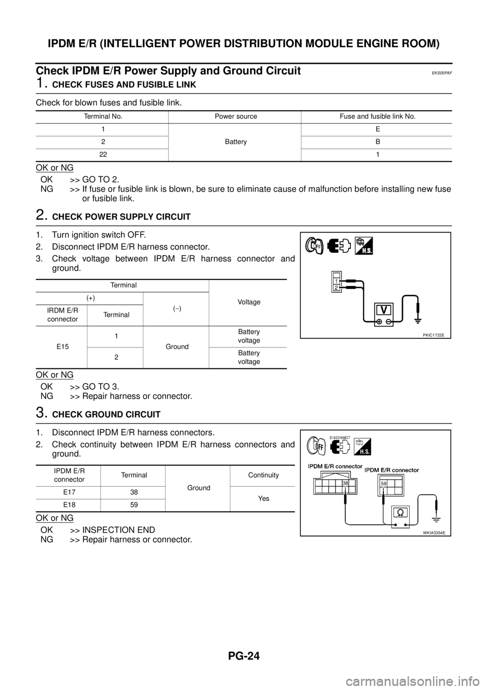
Check IPDM E/R Power Supply and Ground Circuit
EKS00PAF
1.CHECK FUSES AND FUSIBLE LINK
Check for blown fuses and fusible link.
OK or NG
OK >> GO TO 2.
NG >> If fuse or fusible link is blown, be sure to eliminate cause of malfunction before installing new fuse
or fusible link.
2.CHECK POWER SUPPLY CIRCUIT
1. Turn ignition switch OFF.
2. Disconnect IPDM E/R harness connector.
3. Check voltage between IPDM E/R harness connector and
ground.
OK or NG
OK >> GO TO 3.
NG >> Repair harness or connector.
3.CHECK GROUND CIRCUIT
1. Disconnect IPDM E/R harness connectors.
2. Check continuity between IPDM E/R harness connectors and
ground.
OK or NG
OK >> INSPECTION END
NG >> Repair harness or connector.
Terminal No. Power source Fuse and fusible link No.
1
BatteryE
2B
221
Te r m i n a l
Vo l ta g e (+)
(-)
IRDM E/R
connectorTerminal
E151
GroundBattery
voltage
2Battery
voltage
PKIC1722E
IPDM E/R
connectorTerminal
GroundContinuity
E17 38
Ye s
E18 59
WKIA3354E
Page 2554 of 3171

IPDM E/R (INTELLIGENT POWER DISTRIBUTION MODULE ENGINE ROOM)
PG-25
C
D
E
F
G
H
I
J
L
MA
B
PG
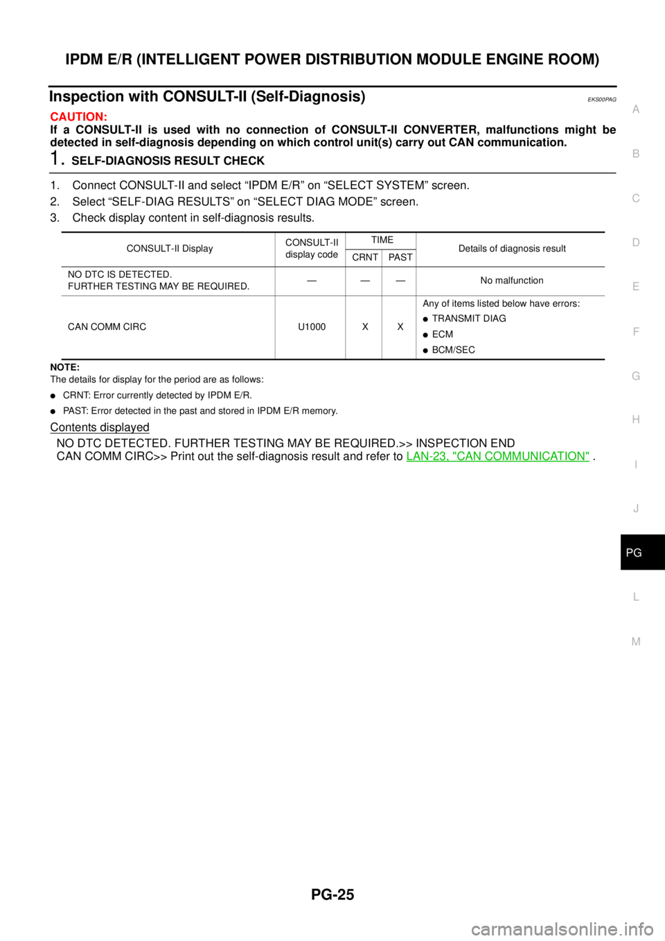
Inspection with CONSULT-II (Self-Diagnosis)EKS00PAG
CAUTION:
If a CONSULT-II is used with no connection of CONSULT-II CONVERTER, malfunctions might be
detected in self-diagnosis depending on which control unit(s) carry out CAN communication.
1.SELF-DIAGNOSIS RESULT CHECK
1. Connect CONSULT-II and select “IPDM E/R” on “SELECT SYSTEM” screen.
2. Select “SELF-DIAG RESULTS” on “SELECT DIAG MODE” screen.
3. Check display content in self-diagnosis results.
NOTE:
The details for display for the period are as follows:
lCRNT: Error currently detected by IPDM E/R.
lPAST: Error detected in the past and stored in IPDM E/R memory.
Contents displayed
NO DTC DETECTED. FURTHER TESTING MAY BE REQUIRED.>> INSPECTION END
CAN COMM CIRC>> Print out the self-diagnosis result and refer toLAN-23, "
CAN COMMUNICATION".
CONSULT-II DisplayCONSULT-II
display codeTIME
Details of diagnosis result
CRNT PAST
NO DTC IS DETECTED.
FURTHER TESTING MAY BE REQUIRED.— — — No malfunction
CAN COMM CIRC U1000 X XAny of items listed below have errors:
lTRANSMIT DIAG
lECM
lBCM/SEC