2005 NISSAN NAVARA engine
[x] Cancel search: enginePage 2476 of 3171

TROUBLE DIAGNOSIS
MTC-89
C
D
E
F
G
H
I
K
L
MA
B
MTC
PERFORMANCE CHART
Test Condition
Testing must be performed as follows:
Test Reading
Recirculating-to-discharge Air Temperature Table
Ambient Air Temperature-to-operating Pressure Table
Vehicle location Indoors or in the shade (in a well-ventilated place)
Doors Closed
Door window Open
Hood Open
TEMP. Max. COLD
Mode switch
(Ventilation) set
Recirculation (REC) switch
(Recirculation) set
Blower speedMax. speed set
Engine speed Idle speed
Operate the air conditioning system for 10 minutes before taking measurements.
Inside air (Recirculating air) at blower assembly inlet
Discharge air temperature at center ventilator
°C(°F) Relative humidity
%Air temperature
°C(°F)
40 - 6020 (68) 4.9 - 6.9 (41 - 44)
25 (77) 8.1 - 10.8 (47- 51)
30 (86) 12.1 - 15.1 (54 - 59)
35 (95) 16.9 - 20.5 (62 - 69)
60 - 8020 (68) 6.9 - 8.8 (44 - 48)
25 (77) 10.6 - 13.1 (51 - 56)
30 (86) 15.1 - 18.2 (59 - 65)
35 (95) 20.5 - 24.0 (69 - 75)
Ambient air
High-pressure (Discharge side)
kPa (kg/cm
2,psi)Low-pressure (Suction side)
kPa (kg/cm2, psi) Relative humidity
%Air temperature
°C(°F)
40 - 6020 (68)920 - 1,020
(9.38 - 10.40, 133.4 - 147.9)190 - 210
(1.94 - 2.14, 27.5 - 30.4)
25 (77)1,250 - 1,390
(12.74 - 14.17, 181.2 - 201.5)240 - 270
(2.45 - 2.75, 34.8 - 39.1)
30 (86)1,590 - 1,770
(16.21 - 18.04, 230.5 - 256.6)300 - 330
(3.06 - 3.36, 43.5 - 47.8)
35 (95)1,900 - 2,110
(19.37 - 21.51, 275.4 - 305.9)360 - 400
(3.67 - 4.08, 52.2 - 58.0)
60 - 8020 (68)1,020 - 1,120
(10.40 - 11.42, 147.9 - 162.3)210 - 230
(2.14 - 2.34, 30.4 - 33.3)
25 (77)1,390 - 1,530
(14.17 - 15.60, 201.5 - 221.8)270 - 300
(2.75 - 3.06, 39.1 - 43.5)
30 (86)1,770 - 1,950
(18.04 - 19.88, 256.6 - 282.7)330 - 360
(3.36 - 3.67, 47.8 - 52.2)
35 (95)2,110 - 2,320
(21.51 - 23.65, 305.9 - 336.3)400 - 440
(4.08 - 4.49, 58.0 - 63.8)
Page 2477 of 3171
MTC-90
TROUBLE DIAGNOSIS
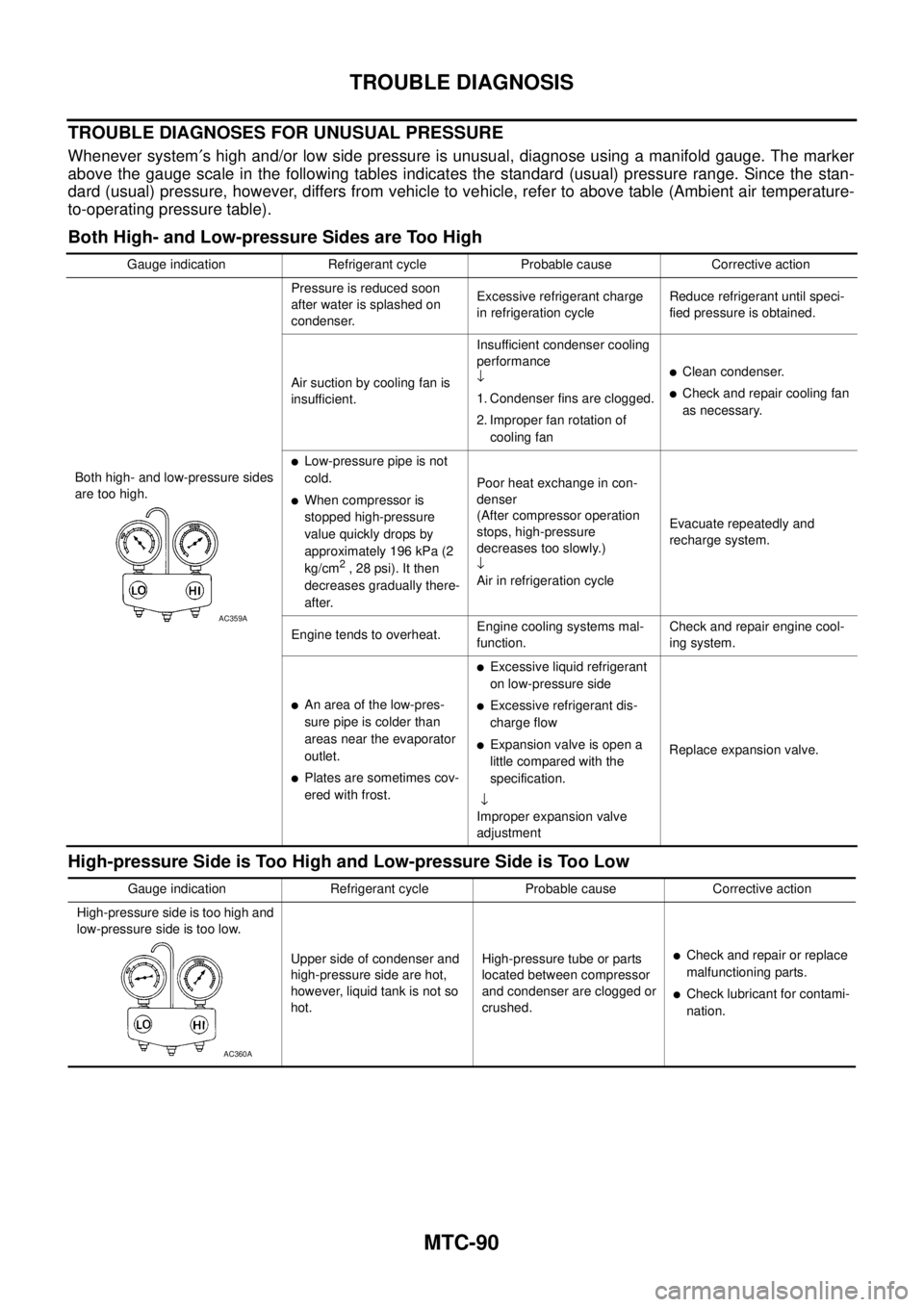
TROUBLE DIAGNOSES FOR UNUSUAL PRESSURE
Whenever system¢s high and/or low side pressure is unusual, diagnose using a manifold gauge. The marker
above the gauge scale in the following tables indicates the standard (usual) pressure range. Since the stan-
dard (usual) pressure, however, differs from vehicle to vehicle, refer to above table (Ambient air temperature-
to-operating pressure table).
Both High- and Low-pressure Sides are Too High
High-pressure Side is Too High and Low-pressure Side is Too Low
Gauge indication Refrigerant cycle Probable cause Corrective action
Both high- and low-pressure sides
are too high.Pressure is reduced soon
after water is splashed on
condenser.Excessive refrigerant charge
in refrigeration cycleReduce refrigerant until speci-
fied pressure is obtained.
Air suction by cooling fan is
insufficient.Insufficient condenser cooling
performance
¯
1. Condenser fins are clogged.
2. Improper fan rotation of
cooling fan
lClean condenser.
lCheck and repair cooling fan
as necessary.
lLow-pressure pipe is not
cold.
lWhen compressor is
stopped high-pressure
value quickly drops by
approximately 196 kPa (2
kg/cm
2,28psi).Itthen
decreases gradually there-
after.Poor heat exchange in con-
denser
(After compressor operation
stops, high-pressure
decreases too slowly.)
¯
Air in refrigeration cycleEvacuate repeatedly and
recharge system.
Engine tends to overheat.Engine cooling systems mal-
function.Check and repair engine cool-
ing system.
lAn area of the low-pres-
sure pipe is colder than
areas near the evaporator
outlet.
lPlates are sometimes cov-
ered with frost.
lExcessive liquid refrigerant
on low-pressure side
lExcessive refrigerant dis-
charge flow
lExpansion valve is open a
littlecomparedwiththe
specification.
¯
Improper expansion valve
adjustmentReplace expansion valve.
AC359A
Gauge indication Refrigerant cycle Probable cause Corrective action
High-pressure side is too high and
low-pressure side is too low.
Upper side of condenser and
high-pressure side are hot,
however, liquid tank is not so
hot.High-pressure tube or parts
located between compressor
and condenser are clogged or
crushed.
lCheck and repair or replace
malfunctioning parts.
lCheck lubricant for contami-
nation.
AC360A
Page 2480 of 3171
TROUBLE DIAGNOSIS
MTC-93
C
D
E
F
G
H
I
K
L
MA
B
MTC
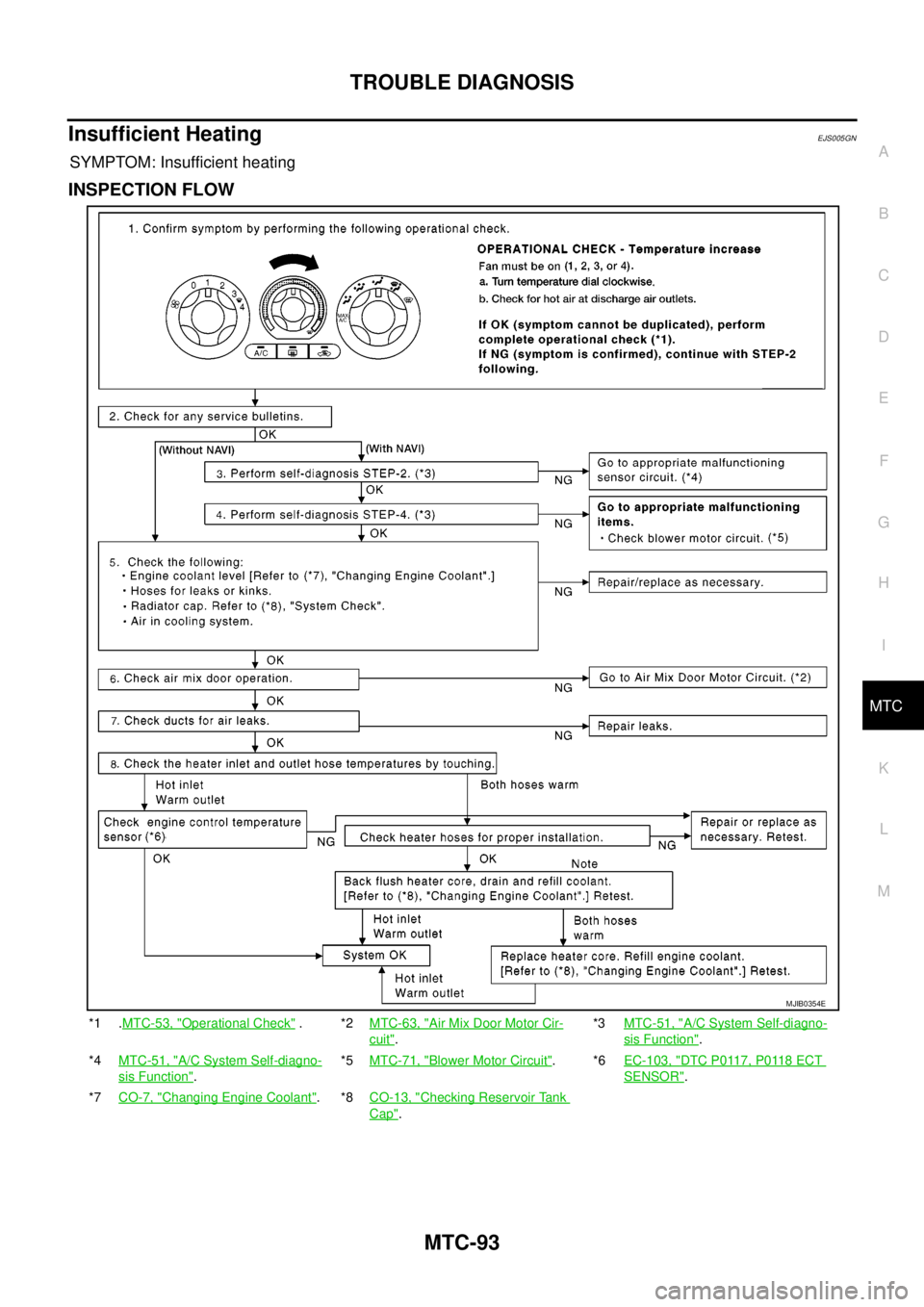
Insufficient HeatingEJS005GN
SYMPTOM: Insufficient heating
INSPECTION FLOW
*1 .MTC-53, "Operational Check".*2MTC-63, "Air Mix Door Motor Cir-
cuit".*3MTC-51, "
A/C System Self-diagno-
sis Function".
*4MTC-51, "
A/C System Self-diagno-
sis Function".*5MTC-71, "
Blower Motor Circuit".*6EC-103, "DTC P0117, P0118 ECT
SENSOR".
*7CO-7, "
Changing Engine Coolant".*8CO-13, "Checking Reservoir Tank
Cap".
MJIB0354E
Page 2492 of 3171
HEATER & COOLING UNIT ASSEMBLY
MTC-105
C
D
E
F
G
H
I
K
L
MA
B
MTC
Removal and InstallationEJS005GY
REMOVAL
1. Discharge the refrigerant from the A/C system. Refer toMTC-118, "Discharging Refrigerant".
2. Drain the coolant from the engine cooling system. Refer toCO-8, "
DRAINING ENGINE COOLANT".
3. Remove the cowl top extension. Refer toEI-20, "
Removal and Installation".
4. Remove the exhaust system. Refer toEX-3, "
Removal and Installation".
5. Disconnect the heater hoses from the heater core.
6. Disconnect the high/low pressure pipes from the expansion valve.
7. Move the two front seats to the rearmost position on the seat track.
8. Remove the instrument panel and console panel. Refer toIP-10, "
Removal and Installation".
9. Remove the steering column. Refer toPS-11, "
Removal and Installation".
10. Disconnect the instrument panel wire harness at the RH and LH in-line connector brackets, and the fuse
block (J/B) electrical connectors. Refer toPG-38, "
Harness Layout".
11. Disconnect the steering member from each side of the vehicle body.
12. Remove the heater and cooling unit assembly with it attached to the steering member, from the vehicle.
CAUTION:
Use care not to damage the seats and interior trim panels when removing the heater and cooling
unit assembly with it attached to the steering member.
13. Remove the heater and cooling unit assembly from the steering member.
INSTALLATION
Installation is in the reverse order of removal.
CAUTION:
lReplace the O-ring of the low-pressure pipe and high-pressure pipe with a new one, and apply
compressor oil to it when installing it.
lAfter charging the refrigerant, check for leaks.
NOTE:
lFill the engine cooling system with the specified coolant mixture. Refer toCO-8, "REFILLING ENGINE
COOLANT".
lRecharge the A/C system. Refer toMTC-118, "Evacuating System and Charging Refrigerant".
Page 2509 of 3171
MTC-122
REFRIGERANT LINES
Removal and Installation for Compressor
EJS005HC
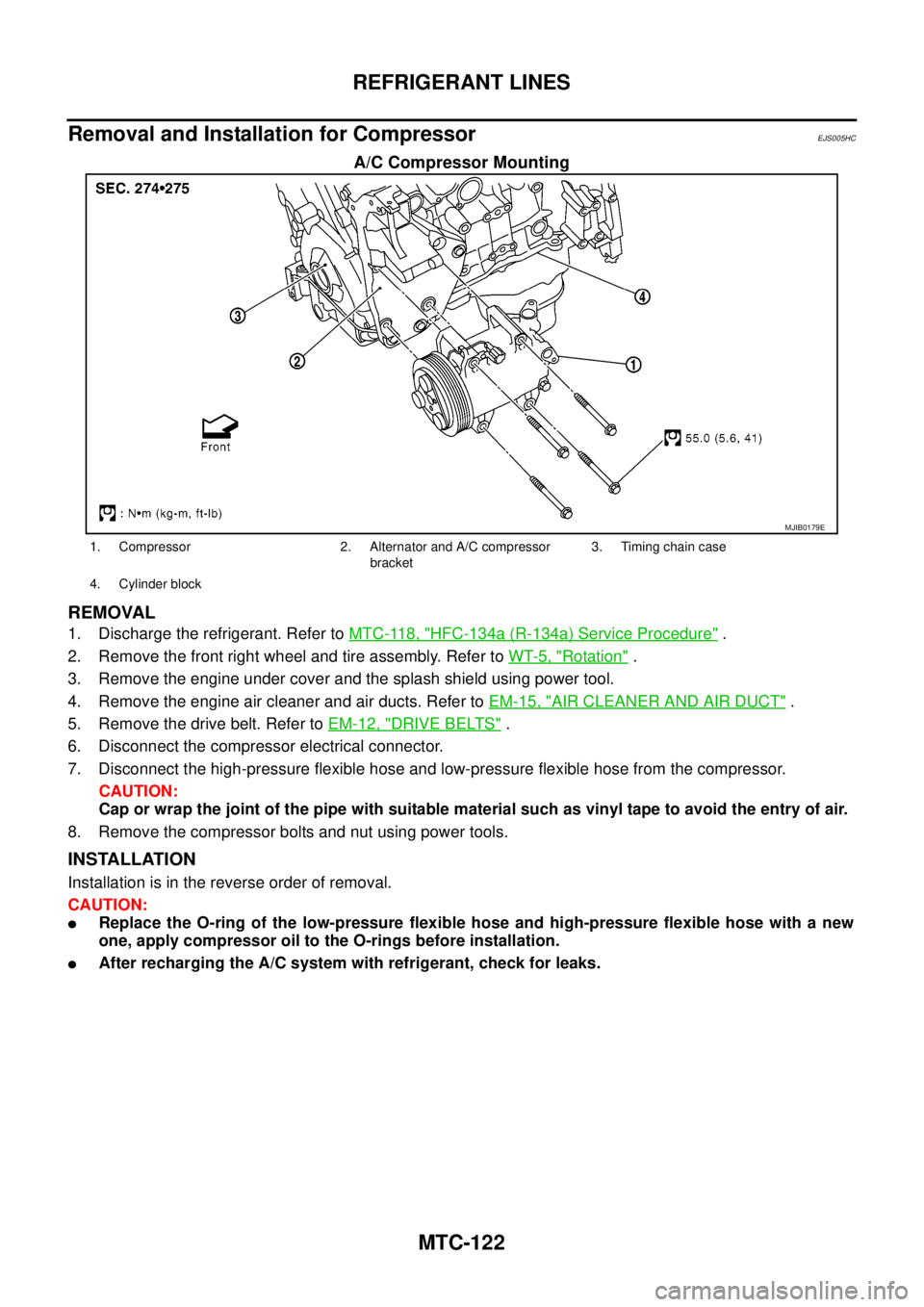
A/C Compressor Mounting
REMOVAL
1. Discharge the refrigerant. Refer toMTC-118, "HFC-134a (R-134a) Service Procedure".
2. Remove the front right wheel and tire assembly. Refer toWT-5, "
Rotation".
3. Remove the engine under cover and the splash shield using power tool.
4. Remove the engine air cleaner and air ducts. Refer toEM-15, "
AIR CLEANER AND AIR DUCT".
5. Remove the drive belt. Refer toEM-12, "
DRIVE BELTS".
6. Disconnect the compressor electrical connector.
7. Disconnect the high-pressure flexible hose and low-pressure flexible hose from the compressor.
CAUTION:
Cap or wrap the joint of the pipe with suitable material such as vinyl tape to avoid the entry of air.
8. Remove the compressor bolts and nut using power tools.
INSTALLATION
Installation is in the reverse order of removal.
CAUTION:
lReplace the O-ring of the low-pressure flexible hose and high-pressure flexible hose with a new
one, apply compressor oil to the O-rings before installation.
lAfter recharging the A/C system with refrigerant, check for leaks.
MJIB0179E
1. Compressor 2. Alternator and A/C compressor
bracket3. Timing chain case
4. Cylinder block
Page 2512 of 3171
REFRIGERANT LINES
MTC-125
C
D
E
F
G
H
I
K
L
MA
B
MTC
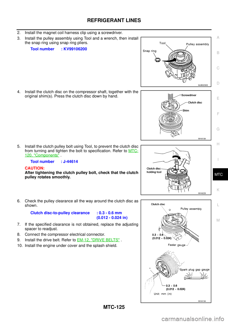
2. Install the magnet coil harness clip using a screwdriver.
3. Install the pulley assembly using Tool and a wrench, then install
the snap ring using snap ring pliers.
4. Install the clutch disc on the compressor shaft, together with the
original shim(s). Press the clutch disc down by hand.
5. Install the clutch pulley bolt using Tool, to prevent the clutch disc
from turning and tighten the bolt to specification. Refer toMTC-
120, "Components".
CAUTION:
After tightening the clutch pulley bolt, check that the clutch
pulley rotates smoothly.
6. Check the pulley clearance all the way around the clutch disc as
shown.
7. If the specified clearance is not obtained, replace the adjusting
spacer to readjust.
8. Connect the compressor electrical connector.
9. Install the drive belt. Refer toEM-12, "
DRIVE BELTS".
10. Install the engine under cover and the splash shield.Tool number : KV99106200
MJIB0290E
WHA184
Tool number : J-44614
WHA229
Clutch disc-to-pulley clearance : 0.3 - 0.6 mm
(0.012 - 0.024 in)
WHA194
Page 2513 of 3171
MTC-126
REFRIGERANT LINES
BREAK-IN OPERATION
When replacing compressor clutch assembly, always conduct the break-in operation. This is done by engag-
ing and disengaging the clutch about 30 times. Break-in operation raises the level of transmitted torque.
Removal and Installation for Low-pressure Flexible HoseEJS005HE
REMOVAL
1. Remove the engine room cover using power tools.
2. Remove the engine air cleaner and air ducts. Refer toEM-15, "
AIR CLEANER AND AIR DUCT".
3. Remove the cowl top extension. Refer toEI-20, "
COWL TOP".
4. Discharge the refrigerant. Refer toMTC-118, "
HFC-134a (R-134a) Service Procedure".
CAUTION:
Cap or wrap the joint of the pipe with suitable material such as vinyl tape to avoid the entry of air.
5. Remove the low-pressure flexible hose. Refer toMTC-120, "
Components".
INSTALLATION
Installation is in the reverse order of removal.
Refer toMTC-120, "
Components".
CAUTION:
lReplace the O-ring of the low-pressure flexible hose with a new one, then apply compressor oil to
it when installing it.
lAfter charging refrigerant, check for leaks.
Removal and Installation for High-pressure Flexible HoseEJS005HF
REMOVAL
1. Remove the engine under cover.
2. Remove the engine air cleaner and air ducts. Refer toEM-15, "
AIR CLEANER AND AIR DUCT"
3. Discharge the refrigerant. Refer toMTC-118, "HFC-134a (R-134a) Service Procedure".
4. Remove the high-pressure flexible hose. Refer toMTC-120, "
Components".
CAUTION:
Cap or wrap the joint of the pipe with suitable material such as vinyl tape to avoid the entry of air.
INSTALLATION
Installation is in the reverse order of removal.
Refer toMTC-120, "
Components".
CAUTION:
lReplace the O-ring of the high-pressure flexible hose with a new one, then apply compressor oil to
it when installing it.
lAfter charging refrigerant, check for leaks.
Removal and Installation for High-pressure PipeEJS005HG
REMOVAL
1. Remove the cowl top extension. Refer toEI-20, "COWL TOP".
2. Disconnect the battery negative cable.
3. Reposition the IPDM E/R aside.
4. Remove the front right wheel and tire assembly. Refer toWT-5, "
Rotation".
5. Position aside the front floor insulator.
6. Discharge the refrigerant. Refer toMTC-118, "
HFC-134a (R-134a) Service Procedure".
7. Remove the low pressure pipe. Refer toMTC-127, "
Removal and Installation for Low-pressure Pipe".
8. Remove the high-pressure pipe. Refer toMTC-120, "
Components".
CAUTION:
Cap or wrap the joint of the pipe with suitable material such as vinyl tape to avoid the entry of air.
INSTALLATION
Installation is in the reverse order of removal.
Refer toMTC-120, "
Components".
Page 2518 of 3171
REFRIGERANT LINES
MTC-131
C
D
E
F
G
H
I
K
L
MA
B
MTC
Checking for Refrigerant LeaksEJS0062F
Perform a visual inspection of all refrigeration parts, fittings, hoses and components for signs of A/C lubricant
leakage, damage and corrosion. A/C lubricant leakage may indicate an area of refrigerant leakage. Allow
extra inspection time in these areas when using either an electronic refrigerant leak detector or fluorescent
dye leak detector.
If dye is observed, confirm the leak with an electronic refrigerant leak detector. It is possible a prior leak was
repaired and not properly cleaned.
When searching for leaks, do not stop when one leak is found but continue to check for additional leaks at all
system components and connections.
When searching for refrigerant leaks using an electronic leak detector, move the probe along the suspected
leak area at 1 to 2 inches per second and no further than 1/4 inch from the component.
CAUTION:
Moving the electronic leak detector probe slower and closer to the suspected leak area will improve
the chances of finding a leak.
Checking System for Leaks Using the Fluorescent Leak DetectorEJS0062G
1. Check A/C system for leaks using the UV lamp and safety goggles [SST: J-42220] in a low sunlight area
(area without windows preferable). Illuminate all components, fittings and lines. The dye will appear as a
bright green/yellow area at the point of leakage. Fluorescent dye observed at the evaporator drain open-
ing indicates an evaporator core assembly (tubes, core or expansion valve) leak.
2. If the suspected area is difficult to see, use an adjustable mirror or wipe the area with a clean shop rag or
cloth, with the UV lamp for dye residue.
3. After the leak is repaired, remove any residual dye using dye cleaner [SST: J-43872] to prevent future mis-
diagnosis.
4. Perform a system performance check and verify the leak repair with an approved electronic refrigerant
leak detector.
NOTE:
Other gases in the work area or substances on the A/C components, for example, anti-freeze, windshield
washer fluid, solvents and lubricants, may falsely trigger the leak detector. Make sure the surfaces to be
checked are clean.
Clean with a dry cloth or blow off with shop air.
Do not allow the sensor tip of the detector to contact with any substance. This can also cause false readings
and may damage the detector.
Dye InjectionEJS0062H
(This procedure is only necessary when recharging the system or when the compressor has seized and was
replaced.)
1. Check A/C system static (at rest) pressure. Pressure must be at least 345 kPa (3.45 bar, 3.52 kg/cm
2,50
psi).
2. Pour one bottle (1/4 ounce / 7.4 cc) of the A/C refrigerant dye into the injector tool [SST: J-41459].
3. Connect the injector tool to the A/C Low-pressure side service fitting.
4. Start engine and switch A/C ON.
5. When the A/C operating (compressor running), inject one bottle (1/4 ounce / 7.4 cc) of fluorescent dye
through the low-pressure service valve using dye injector tool J-41459 (refer to the manufacture’s operat-
ing instructions).
6. With the engine still running, disconnect the injector tool from the service fitting.
CAUTION:
Be careful the A/C system or replacing a component, pour the dye directly into the open system
connection and proceed with the service procedures.
7. Operate the A/C system for a minimum of 20 minutes to mix the dye with the system oil. Depending on the
leak size, operating conditions and location of the leak, it may take from minutes to days for the dye to
penetrate a leak and become visible.