Page 3064 of 3171

TROUBLE DIAGNOSIS FOR SYMPTOMS
TF-97
C
E
F
G
H
I
J
K
L
MA
B
TF
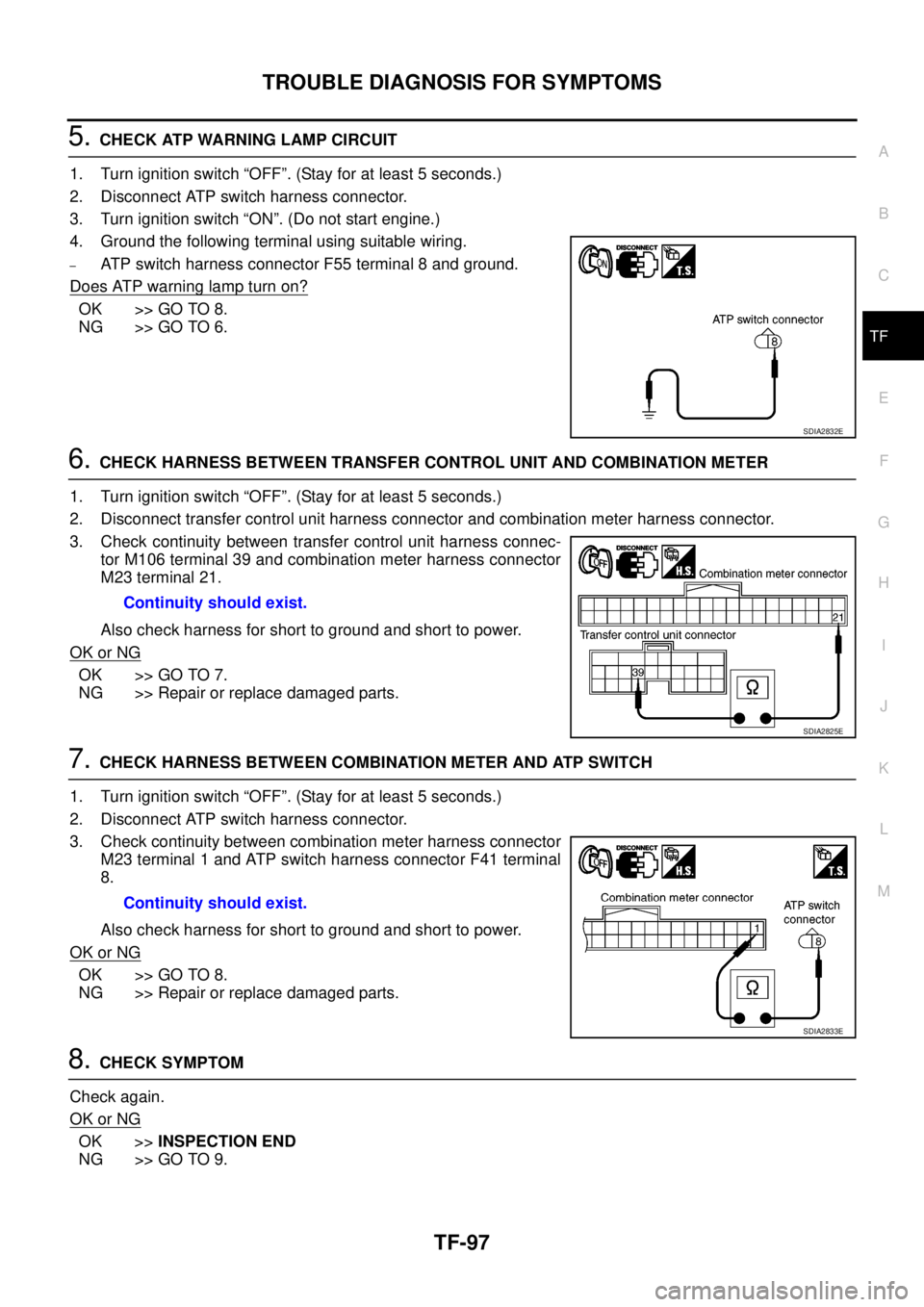
5.CHECK ATP WARNING LAMP CIRCUIT
1. Turn ignition switch “OFF”. (Stay for at least 5 seconds.)
2. Disconnect ATP switch harness connector.
3. Turn ignition switch “ON”. (Do not start engine.)
4. Ground the following terminal using suitable wiring.
–ATP switch harness connector F55 terminal 8 and ground.
Does ATP warning lamp turn on?
OK >> GO TO 8.
NG >> GO TO 6.
6.CHECK HARNESS BETWEEN TRANSFER CONTROL UNIT AND COMBINATION METER
1. Turn ignition switch “OFF”. (Stay for at least 5 seconds.)
2. Disconnect transfer control unit harness connector and combination meter harness connector.
3. Check continuity between transfer control unit harness connec-
tor M106 terminal 39 and combination meter harness connector
M23 terminal 21.
Also check harness for short to ground and short to power.
OK or NG
OK >> GO TO 7.
NG >> Repair or replace damaged parts.
7.CHECK HARNESS BETWEEN COMBINATION METER AND ATP SWITCH
1. Turn ignition switch “OFF”. (Stay for at least 5 seconds.)
2. Disconnect ATP switch harness connector.
3. Check continuity between combination meter harness connector
M23 terminal 1 and ATP switch harness connector F41 terminal
8.
Also check harness for short to ground and short to power.
OK or NG
OK >> GO TO 8.
NG >> Repair or replace damaged parts.
8.CHECK SYMPTOM
Check again.
OK or NG
OK >>INSPECTION END
NG >> GO TO 9.
SDIA2832E
Continuity should exist.
SDIA2825E
Continuity should exist.
SDIA2833E
Page 3079 of 3171

TF-112
TRANSFER ASSEMBLY
INSTALLATION
Note the following, and install in the reverse order of removal.
lTighten the bolts to specification.
lAfter the installation, check the transfer fluid level and fluid leak-
age. Refer toTF-12, "
FLUID LEAKAGE AND FLUID LEVEL".
lAfter filling, start the engine for one minute. Then stop the
engine and recheck the transfer fluid.
lAfter the installation, check the 4WD shift indicator pattern. If
NG, adjust the position between the transfer assembly and
transfer control unit. Refer toTF-4, "
Precautions for Transfer
Assembly and Transfer Control Unit Replacement".
Disassembly and AssemblyEDS0032P
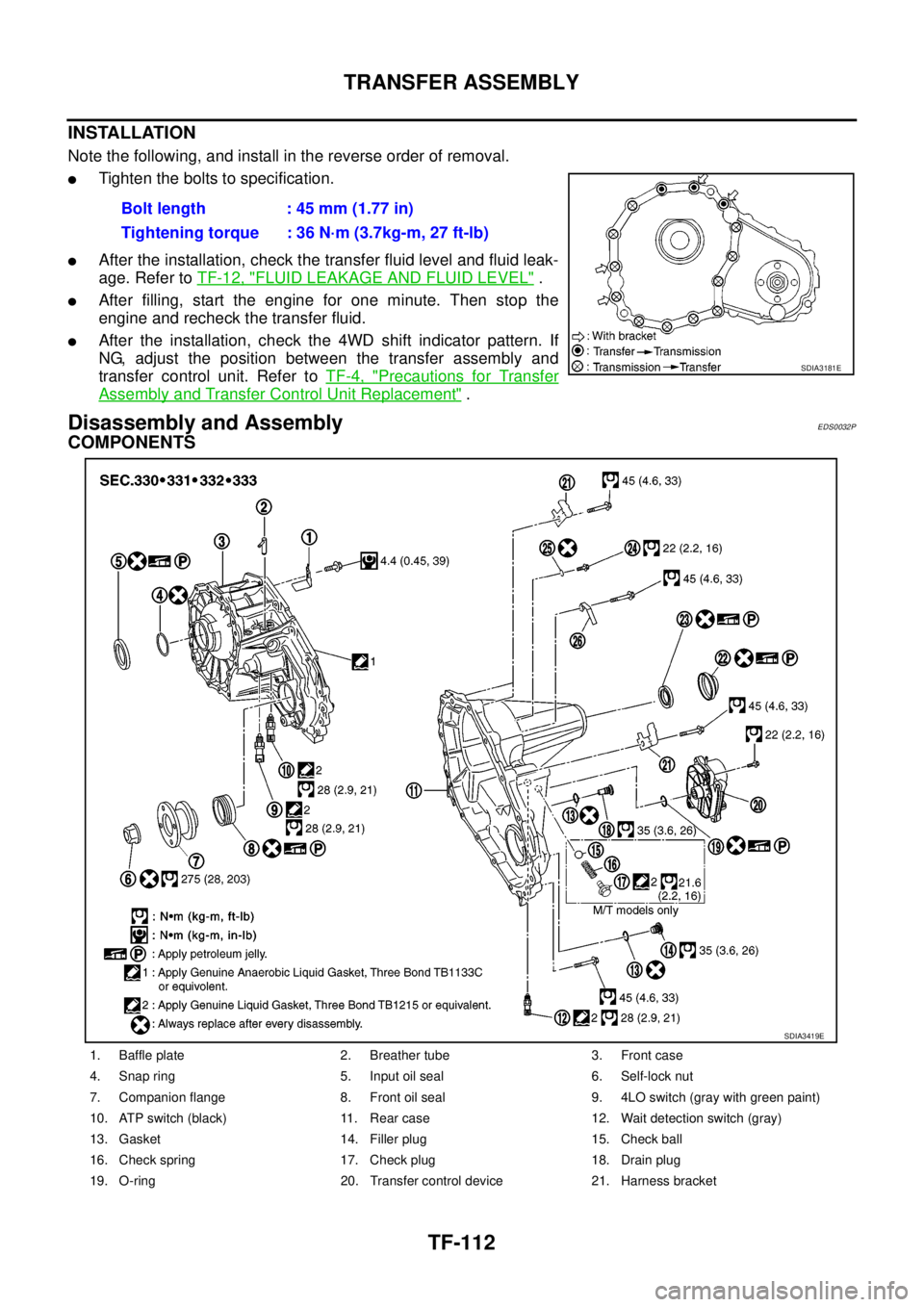
COMPONENTS
Bolt length : 45 mm (1.77 in)
Tightening torque : 36 N·m (3.7kg-m, 27 ft-lb)
SDIA3181E
1. Baffle plate 2. Breather tube 3. Front case
4. Snap ring 5. Input oil seal 6. Self-lock nut
7. Companion flange 8. Front oil seal 9. 4LO switch (gray with green paint)
10. ATP switch (black) 11. Rear case 12. Wait detection switch (gray)
13. Gasket 14. Filler plug 15. Check ball
16. Check spring 17. Check plug 18. Drain plug
19. O-ring 20. Transfer control device 21. Harness bracket
SDIA3419E
Page 3115 of 3171
WW-4
FRONT WIPER AND WASHER SYSTEM
FRONT WIPER AND WASHER SYSTEM
PFP:28810
Components Parts and Harness Connector LocationEKS00P4U
System DescriptionEKS00P4V
lAll front wiper relays (MAIN, LOW/HIGH) are located in IPDM E/R (intelligent power distribution module
engine room).
lWiper switch (combination switch) is composed of a combination of 5 output terminals and 5 input termi-
nals. Terminal combination status is read by BCM (body control module) when the wiper switch is turned
ON.
lBCM controls front wiper LO, HI, and INT (intermittent) operation.
lIPDM E/R operates the wiper motor according to CAN communication signals from the BCM.
Power is supplied at all times
lto ignition relay (located in IPDM E/R), from battery directly,
lthrough 50A fusible link (letter G, located in fuse and fusible link box)
lto BCM terminal 57,
lthrough 30A fuse (No. 39, located in IPDM E/R)
lto front wiper main relay (located in IPDM E/R).
SKIB6805E
Page 3150 of 3171
HEADLAMP WASHER
WW-39
C
D
E
F
G
H
I
J
L
MA
B
WW
HEADLAMP WASHERPFP:28620
Components Parts and Harness Connector LocationEKS00P67
System DescriptionEKS00P68
Headlamp washer operates under the following conditions.
lWhen lighting switch is in 1ST position
lWhen daytime light system is operating
lWhen auto light system is operating (LOW beam is ON)
When the headlamp washer switch is ON position the BCM (body control module) receives input signal
requesting the headlamp washer operates. The CPU (central processing unit) of the IPDM E/R (intelligent
power distribution module engine room) controls the headlamp washer relay coil. When activated this relay
directs power headlamp washer motor.
SKIB6860E