2005 NISSAN NAVARA engine
[x] Cancel search: enginePage 3013 of 3171
![NISSAN NAVARA 2005 Repair Workshop Manual TF-46
TROUBLE DIAGNOSIS
CAUTION:
If “CAN COMM CIRCUIT [U1000]” is displayed with other DTCs, first perform the trouble diagnosis for CAN communication
line.
NOTE:
If “SHIFT ACT POSI SW [P1818]� NISSAN NAVARA 2005 Repair Workshop Manual TF-46
TROUBLE DIAGNOSIS
CAUTION:
If “CAN COMM CIRCUIT [U1000]” is displayed with other DTCs, first perform the trouble diagnosis for CAN communication
line.
NOTE:
If “SHIFT ACT POSI SW [P1818]�](/manual-img/5/57362/w960_57362-3012.png)
TF-46
TROUBLE DIAGNOSIS
CAUTION:
If “CAN COMM CIRCUIT [U1000]” is displayed with other DTCs, first perform the trouble diagnosis for CAN communication
line.
NOTE:
If “SHIFT ACT POSI SW [P1818]” or “SHIFT ACT CIR [P1819]” is displayed, first erase self-diagnostic results. (“SHIFT ACT POSI SW
[P1818]” or “SHIFT ACT CIR [P1819]” may be displayed after installing transfer control unit or transfer assembly.)
How to Erase Self-diagnostic Results
1. Perform applicable inspection of malfunctioning item and then repair or replace.
2. Start engine and select “SELF-DIAG RESULTS” mode for “ALL MODE AWD/4WD” with CONSULT-II.
3. Touch “ERASE” on CONSULT-II screen to erase DTC memory.
CAUTION:
If memory cannot be erased, perform applicable diagnosis.
CONTROL UNIT 4
[P1809]AD converter system of transfer control unit is malfunctioning.TF-54, "Transfer Control Unit"
4L POSI SW TF
[P1810]Improper signal from 4LO switch is input due to open or short circuit.TF-56, "4LO Switch"
BATTERY VOLTAGE
[P1811]Power supply voltage for transfer control unit is abnormally low
while driving.TF-52, "Power Supply Circuit For
Transfer Control Unit"
4WD MODE SW
[P1813]More than two switch inputs are simultaneously detected due to
short circuit of 4WD shift switch.TF-59, "4WD Shift Switch"
4WD DETECT SWITCH
[P1814]Improper signal from wait detection switch is input due to open or
short circuit.TF-63, "Wait Detection Switch"
PNP SW/CIRC
[P1816]When A/T PNP switch signal is malfunction or communication error
between the vehicles.TF-66, "PNP Switch Signal
(TCM)"
SHIFT ACTUATOR
[P1817]
lMotor does not operate properly due to open or short circuit in
actuator motor.
lMalfunction is detected in the actuator motor. (When 4WD shift
switch is operated and actuator motor is not operated)
lMalfunction is detected in transfer shift high relay and transfer
shift low relay.TF-67, "
Actuator Motor"
SHIFT ACT POSI SW
[P1818]lImproper signal from actuator position switch is input due to open
or short circuit.
lMalfunction is detected in actuator position switch.TF-75, "
Actuator Position
Switch"
SHIFT ACT CIR
[P1819]lMalfunction is detected in transfer shut off relay 1 and transfer
shut off relay 2.
lMalfunction occurs in transfer control device drive circuit.TF-52, "
Power Supply Circuit For
Transfer Control Unit",TF-78,
"Transfer Control Device"
ENGINE SPEED SIG
[P1820]lMalfunction is detected in engine speed signal that is output from
ECM through CAN communication.
lImproper signal is input while driving.TF-81, "
Engine Speed Signal
(ECM)"
CAN COMM CIRCUIT
[U1000]Malfunction has been detected from CAN communication line.TF-82, "CAN Communication
Line"
NO DTC IS DETECTED.
FURTHER TESTING MAY
BE REQUIRED.No NG item has been detected. — Items (CONSULT-II screen
terms)Diagnostic item is detected when... Check item
Page 3014 of 3171

TROUBLE DIAGNOSIS
TF-47
C
E
F
G
H
I
J
K
L
MA
B
TF
DATA MONITOR MODE
Operation Procedure
1. Perform “CONSULT-II SETTING PROCEDURE”. Refer toTF-44, "CONSULT-II SETTING PROCEDURE"
.
2. Touch “DATA MONITOR”.
3. Select from “SELECT MONITOR ITEM”, screen of data monitor mode is displayed.
NOTE:
When malfunction is detected, CONSULT-II performs REAL-TIME DIAGNOSIS.
Also, any malfunction detected while in this mode will be displayed in real time.
Display Item List
´: Standard –: Not applicable
Monitored item (Unit)Monitor item selection
Remarks
ECU INPUT
SIGNALSMAIN
SIGNALSSELECTION
FROM MENU
VHCL/S SEN·FR [km/h] or [mph]´–´For ABS models, wheel speed calculated
by ABS actuator and electric unit (control
unit). Signal input with CAN communica-
tion line.
VHCL/S SEN·RR [km/h] or [mph]´–´For ABS models, wheel speed calculated
by TCM. Signal input with CAN communi-
cation line.
ENGINE SPEED [rpm]´–´Engine speed is displayed.
Signal input with CAN communication line.
BATTERY VOLT [V]´–´Power supply voltage for transfer control
unit.
2WD SWITCH [ON/OFF]´–´
4WD shift switch signal status is dis-
played.
(4L means 4LO of 4WD shift switch.) 4H SWITCH [ON/OFF]´–´
4L SWITCH [ON/OFF]´–´
4L POSI SW [ON/OFF]´–´This means 4LO switch.
4LO switch signal status is displayed.
ATP SWITCH [ON/OFF]´–´ATP switch signal status is displayed.
WAIT DETCT SW [ON/OFF]´–´Wait detection switch signal status is dis-
played.
4WD MODE [2H/4H/4L] –´´Control status of 4WD recognized by
transfer control unit. (2WD, 4H or 4LO)
VHCL/S COMP [km/h] or [mph] –´´Vehicle speed recognized by transfer con-
trol unit.
SHIFT ACT 1 [ON/OFF] –´´Output condition to actuator motor (clock-
wise)
SHIFT AC MON 1 [ON/OFF] – –´Check signal for transfer control unit sig-
nal output
SHIFT ACT 2 [ON/OFF] –´´Output condition to actuator motor (coun-
terclockwise)
SHIFT AC MON 2 [ON/OFF] – –´Check signal for transfer control unit sig-
nal output
SFT ACT/R MON [ON/OFF] – –´Operating condition of actuator motor
relay (integrated in transfer control unit)
SHIFT POS SW 1 [ON/OFF]´–´Condition of actuator position switch 1
SHIFT POS SW 2 [ON/OFF]´–´Condition of actuator position switch 2
SHIFT POS SW 3 [ON/OFF]´–´Condition of actuator position switch 3
SHIFT POS SW 4 [ON/OFF]´–´Condition of actuator position switch 4
Page 3016 of 3171
TROUBLE DIAGNOSIS
TF-49
C
E
F
G
H
I
J
K
L
MA
B
TF
Self-Diagnostic ProcedureEDS0031X
SELF-DIAGNOSTIC PROCEDURE (WITH CONSULT-II)
Refer toTF-45, "SELF-DIAG RESULT MODE".
SELF-DIAGNOSTIC PROCEDURE (WITHOUT CONSULT-II)
Description
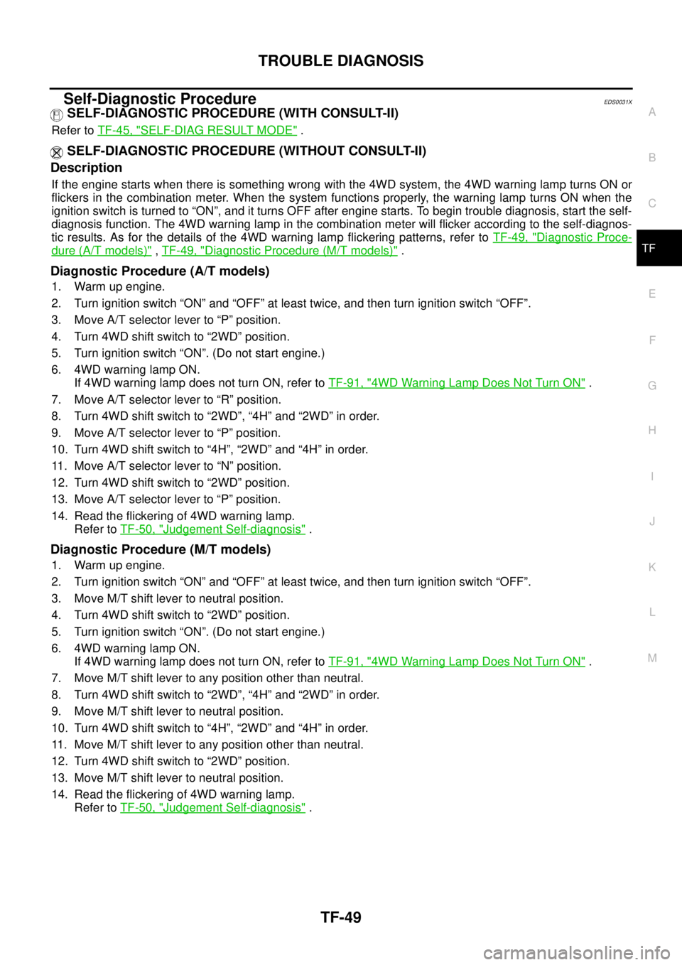
If the engine starts when there is something wrong with the 4WD system, the 4WD warning lamp turns ON or
flickers in the combination meter. When the system functions properly, the warning lamp turns ON when the
ignition switch is turned to “ON”, and it turns OFF after engine starts. To begin trouble diagnosis, start the self-
diagnosis function. The 4WD warning lamp in the combination meter will flicker according to the self-diagnos-
tic results. As for the details of the 4WD warning lamp flickering patterns, refer toTF-49, "
Diagnostic Proce-
dure (A/T models)",TF-49, "Diagnostic Procedure (M/T models)".
Diagnostic Procedure (A/T models)
1. Warm up engine.
2. Turn ignition switch “ON” and “OFF” at least twice, and then turn ignition switch “OFF”.
3. Move A/T selector lever to “P” position.
4. Turn 4WD shift switch to “2WD” position.
5. Turn ignition switch “ON”. (Do not start engine.)
6. 4WD warning lamp ON.
If 4WD warning lamp does not turn ON, refer toTF-91, "
4WD Warning Lamp Does Not Turn ON".
7. Move A/T selector lever to “R” position.
8. Turn 4WD shift switch to “2WD”, “4H” and “2WD” in order.
9. Move A/T selector lever to “P” position.
10. Turn 4WD shift switch to “4H”, “2WD” and “4H” in order.
11. Move A/T selector lever to “N” position.
12. Turn 4WD shift switch to “2WD” position.
13. Move A/T selector lever to “P” position.
14. Read the flickering of 4WD warning lamp.
Refer toTF-50, "
Judgement Self-diagnosis".
Diagnostic Procedure (M/T models)
1. Warm up engine.
2. Turn ignition switch “ON” and “OFF” at least twice, and then turn ignition switch “OFF”.
3. Move M/T shift lever to neutral position.
4. Turn 4WD shift switch to “2WD” position.
5. Turn ignition switch “ON”. (Do not start engine.)
6. 4WD warning lamp ON.
If 4WD warning lamp does not turn ON, refer toTF-91, "
4WD Warning Lamp Does Not Turn ON".
7. Move M/T shift lever to any position other than neutral.
8. Turn 4WD shift switch to “2WD”, “4H” and “2WD” in order.
9. Move M/T shift lever to neutral position.
10. Turn 4WD shift switch to “4H”, “2WD” and “4H” in order.
11. Move M/T shift lever to any position other than neutral.
12. Turn 4WD shift switch to “2WD” position.
13. Move M/T shift lever to neutral position.
14. Read the flickering of 4WD warning lamp.
Refer toTF-50, "
Judgement Self-diagnosis".
Page 3017 of 3171
TF-50
TROUBLE DIAGNOSIS
Judgement Self-diagnosis
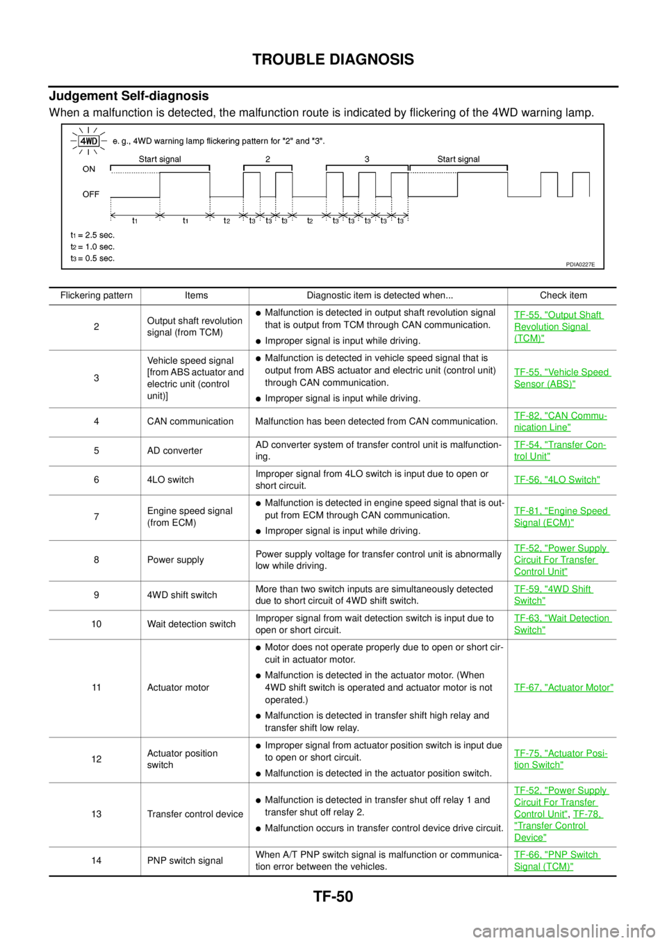
When a malfunction is detected, the malfunction route is indicated by flickering of the 4WD warning lamp.
PDIA0227E
Flickering pattern Items Diagnostic item is detected when... Check item
2Output shaft revolution
signal (from TCM)
lMalfunction is detected in output shaft revolution signal
that is output from TCM through CAN communication.
lImproper signal is input while driving.TF-55, "
Output Shaft
Revolution Signal
(TCM)"
3Vehicle speed signal
[from ABS actuator and
electric unit (control
unit)]
lMalfunction is detected in vehicle speed signal that is
output from ABS actuator and electric unit (control unit)
through CAN communication.
lImproper signal is input while driving.TF-55, "
Vehicle Speed
Sensor (ABS)"
4 CAN communication Malfunction has been detected from CAN communication.TF-82, "CAN Commu-
nication Line"
5 AD converterAD converter system of transfer control unit is malfunction-
ing.TF-54, "Transfer Con-
trol Unit"
6 4LO switchImproper signal from 4LO switch is input due to open or
short circuit.TF-56, "4LO Switch"
7Engine speed signal
(from ECM)
lMalfunction is detected in engine speed signal that is out-
put from ECM through CAN communication.
lImproper signal is input while driving.TF-81, "
Engine Speed
Signal (ECM)"
8 Power supplyPower supply voltage for transfer control unit is abnormally
low while driving.TF-52, "
Power Supply
Circuit For Transfer
Control Unit"
9 4WD shift switchMore than two switch inputs are simultaneously detected
due to short circuit of 4WD shift switch.TF-59, "4WD Shift
Switch"
10 Wait detection switchImproper signal from wait detection switch is input due to
open or short circuit.TF-63, "Wait Detection
Switch"
11 Actuator motor
lMotor does not operate properly due to open or short cir-
cuit in actuator motor.
lMalfunction is detected in the actuator motor. (When
4WD shift switch is operated and actuator motor is not
operated.)
lMalfunction is detected in transfer shift high relay and
transfer shift low relay.TF-67, "
Actuator Motor"
12Actuator position
switch
lImproper signal from actuator position switch is input due
to open or short circuit.
lMalfunction is detected in the actuator position switch.TF-75, "
Actuator Posi-
tion Switch"
13 Transfer control device
lMalfunction is detected in transfer shut off relay 1 and
transfer shut off relay 2.
lMalfunction occurs in transfer control device drive circuit.TF-52, "
Power Supply
Circuit For Transfer
Control Unit",TF-78,
"Transfer Control
Device"
14 PNP switch signalWhen A/T PNP switch signal is malfunction or communica-
tion error between the vehicles.TF-66, "PNP Switch
Signal (TCM)"
Page 3020 of 3171
TROUBLE DIAGNOSIS FOR SYSTEM
TF-53
C
E
F
G
H
I
J
K
L
MA
B
TF
DIAGNOSTIC PROCEDURE
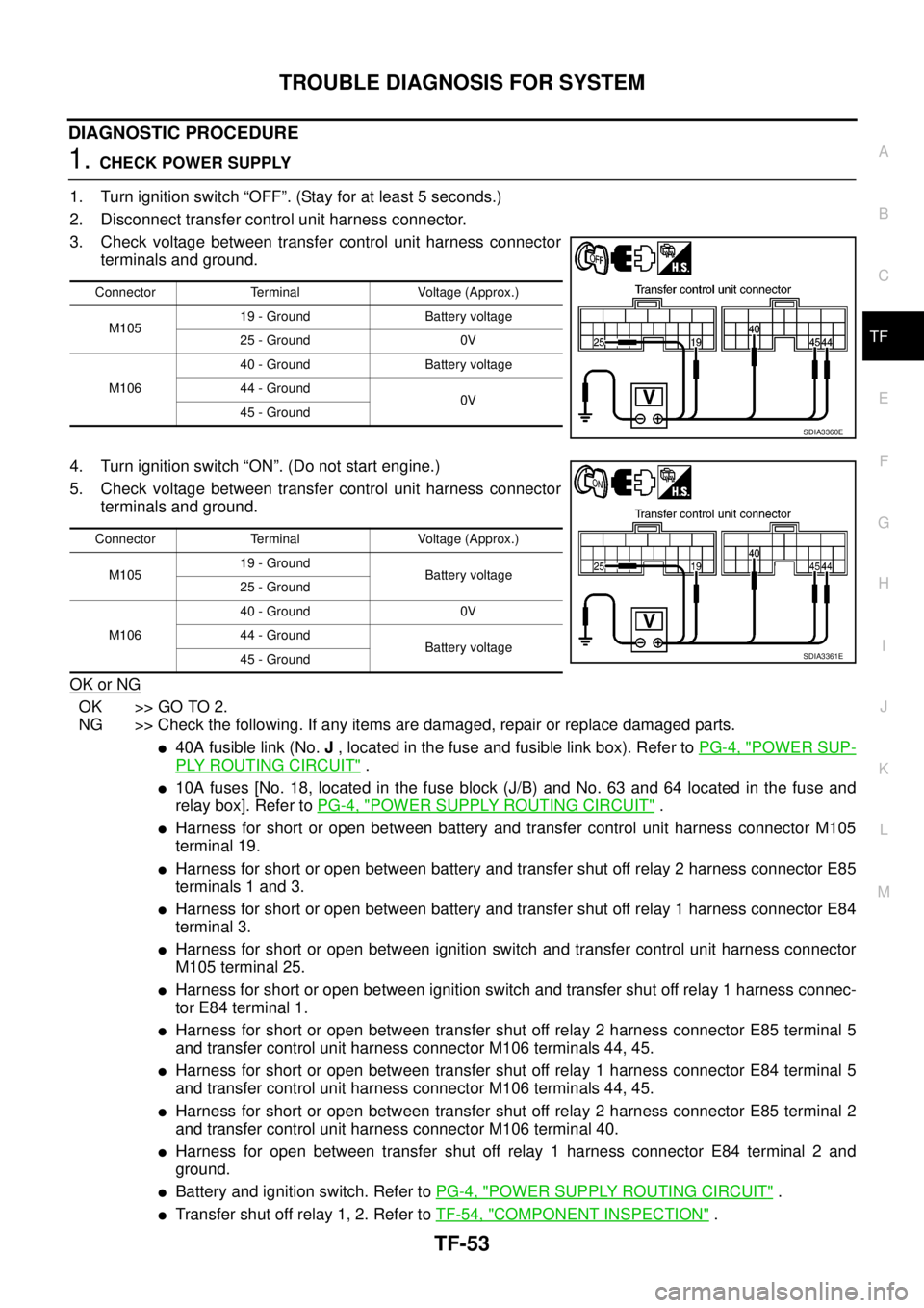
1.CHECK POWER SUPPLY
1. Turn ignition switch “OFF”. (Stay for at least 5 seconds.)
2. Disconnect transfer control unit harness connector.
3. Check voltage between transfer control unit harness connector
terminals and ground.
4. Turn ignition switch “ON”. (Do not start engine.)
5. Check voltage between transfer control unit harness connector
terminals and ground.
OK or NG
OK >> GO TO 2.
NG >> Check the following. If any items are damaged, repair or replace damaged parts.
l40A fusible link (No.J, located in the fuse and fusible link box). Refer toPG-4, "POWER SUP-
PLY ROUTING CIRCUIT".
l10A fuses [No. 18, located in the fuse block (J/B) and No. 63 and 64 located in the fuse and
relay box]. Refer toPG-4, "
POWER SUPPLY ROUTING CIRCUIT".
lHarness for short or open between battery and transfer control unit harness connector M105
terminal 19.
lHarness for short or open between battery and transfer shut off relay 2 harness connector E85
terminals 1 and 3.
lHarness for short or open between battery and transfer shut off relay 1 harness connector E84
terminal 3.
lHarness for short or open between ignition switch and transfer control unit harness connector
M105 terminal 25.
lHarness for short or open between ignition switch and transfer shut off relay 1 harness connec-
tor E84 terminal 1.
lHarness for short or open between transfer shut off relay 2 harness connector E85 terminal 5
and transfer control unit harness connector M106 terminals 44, 45.
lHarness for short or open between transfer shut off relay 1 harness connector E84 terminal 5
and transfer control unit harness connector M106 terminals 44, 45.
lHarness for short or open between transfer shut off relay 2 harness connector E85 terminal 2
and transfer control unit harness connector M106 terminal 40.
lHarness for open between transfer shut off relay 1 harness connector E84 terminal 2 and
ground.
lBattery and ignition switch. Refer toPG-4, "POWER SUPPLY ROUTING CIRCUIT".
lTransfer shut off relay 1, 2. Refer toTF-54, "COMPONENT INSPECTION".
Connector Terminal Voltage (Approx.)
M10519 - Ground Battery voltage
25 - Ground 0V
M10640 - Ground Battery voltage
44 - Ground
0V
45 - Ground
SDIA3360E
Connector Terminal Voltage (Approx.)
M10519 - Ground
Battery voltage
25 - Ground
M10640 - Ground 0V
44 - Ground
Battery voltage
45 - Ground
SDIA3361E
Page 3022 of 3171
TROUBLE DIAGNOSIS FOR SYSTEM
TF-55
C
E
F
G
H
I
J
K
L
MA
B
TF
2.PERFORM SELF-DIAGNOSIS (WITH CONSULT-II)
With CONSULT-II
1. Turn ignition switch “ON”. (Do not start engine.)
2. Select “SELF-DIAG RESULTS” mode for “ALL MODE AWD/4WD” with CONSULT-II.
3. Touch “ERASE”.
4. Turn ignition switch “OFF” and wait at least 10 seconds.
5. Perform the self-diagnosis again.
Is the
“CONTROL UNIT 1 [P1802]”,“CONTROL UNIT 2 [P1803]”,“CONTROL UNIT 3 [P1804]”or“CONTROL
UNIT 4 [P1809]”displayed?
YES >> Replace transfer control unit. Refer toTF-100, "Removal and Installation".
NO >>INSPECTION END
3.PERFORM SELF-DIAGNOSIS (WITHOUT CONSULT-II)
Without CONSULT-II
1. Perform the self-diagnosis and then erase self-diagnostic results. Refer toTF-49, "
SELF-DIAGNOSTIC
PROCEDURE (WITHOUT CONSULT-II)"andTF-51, "ERASE SELF-DIAGNOSIS".
2. Perform the self-diagnosis again.
Do the self-diagnostic results indicate AD converter?
YES >> Replace transfer control unit. Refer toTF-100, "Removal and Installation".
NO >>INSPECTION END
Output Shaft Revolution Signal (TCM)EDS00320
DIAGNOSTIC PROCEDURE
1.CHECK DTC WITH TCM
Perform self-diagnosis with TCM. Refer toAT-80, "
SELF-DIAGNOSTIC RESULT MODE".
Is any malfunction detected by self-diagnosis?
YES >> Check the malfunctioning system.
NO >> GO TO 2.
2.CHECK TRANSFER CONTROL UNIT
Check transfer control unit input/output signal. Refer toTF-38, "
Transfer Control Unit Input/Output Signal Ref-
erence Values".
OK or NG
OK >> GO TO 3.
NG >> Check transfer control unit pin terminals for damage or loose connection with harness connector.
If any items are damaged, repair or replace damaged parts.
3.CHECK DTC
Perform the self-diagnosis, after driving a vehicle for a while.
OK or NG
OK >>INSPECTION END
NG >> Perform self-diagnosis with TCM again. Refer toAT-80, "
SELF-DIAGNOSTIC RESULT MODE".
Vehicle Speed Sensor (ABS)EDS00321
DIAGNOSTIC PROCEDURE
1.CHECK DTC WITH ABS ACTUATOR AND ELECTRIC UNIT (CONTROL UNIT)
Perform self-diagnosis with ABS actuator and electric unit (control unit). Refer toBRC-18, "
Self-Diagnosis".
Is any malfunction detected by self-diagnosis?
YES >> Check the malfunctioning system.
NO >> GO TO 2.
Page 3023 of 3171
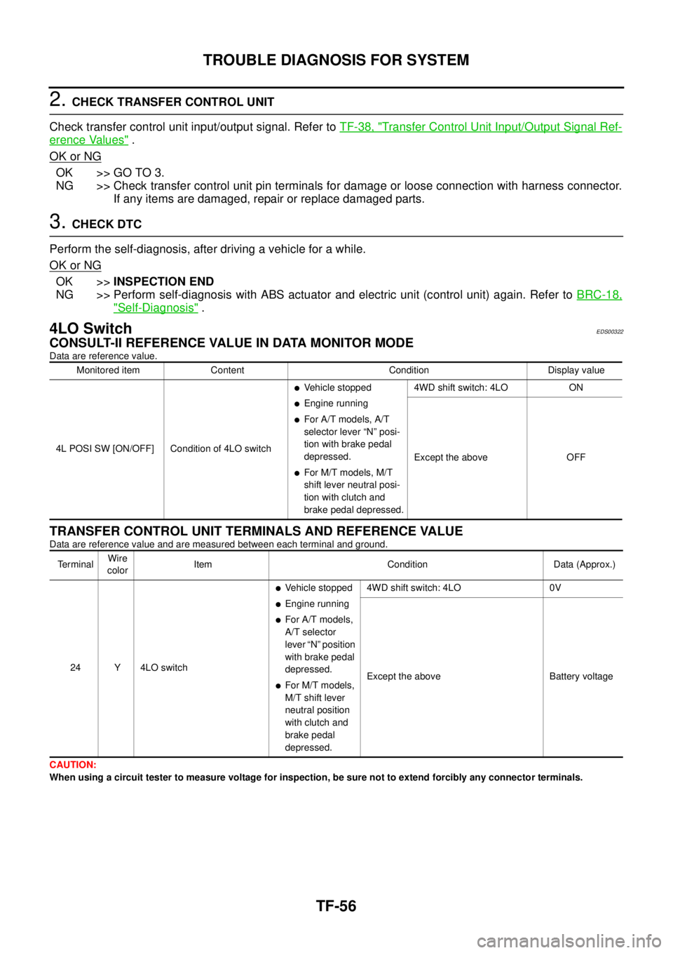
TF-56
TROUBLE DIAGNOSIS FOR SYSTEM
2.CHECK TRANSFER CONTROL UNIT
Check transfer control unit input/output signal. Refer toTF-38, "
Transfer Control Unit Input/Output Signal Ref-
erence Values".
OK or NG
OK >> GO TO 3.
NG >> Check transfer control unit pin terminals for damage or loose connection with harness connector.
If any items are damaged, repair or replace damaged parts.
3.CHECK DTC
Perform the self-diagnosis, after driving a vehicle for a while.
OK or NG
OK >>INSPECTION END
NG >> Perform self-diagnosis with ABS actuator and electric unit (control unit) again. Refer toBRC-18,
"Self-Diagnosis".
4LO SwitchEDS00322
CONSULT-II REFERENCE VALUE IN DATA MONITOR MODE
Data are reference value.
TRANSFER CONTROL UNIT TERMINALS AND REFERENCE VALUE
Data are reference value and are measured between each terminal and ground.
CAUTION:
When using a circuit tester to measure voltage for inspection, be sure not to extend forcibly any connector terminals.Monitored item Content Condition Display value
4L POSI SW [ON/OFF] Condition of 4LO switch
lVehicle stopped
lEngine running
lFor A/T models, A/T
selector lever “N” posi-
tion with brake pedal
depressed.
lFor M/T models, M/T
shift lever neutral posi-
tion with clutch and
brake pedal depressed.4WD shift switch: 4LO ON
Except the above OFF
Te r m i n a lWire
colorItem Condition Data (Approx.)
24 Y 4LO switch
lVehicle stopped
lEngine running
lFor A/T models,
A/T selector
lever “N” position
with brake pedal
depressed.
lFor M/T models,
M/T shift lever
neutral position
with clutch and
brake pedal
depressed.4WD shift switch: 4LO 0V
Except the above Battery voltage
Page 3024 of 3171
TROUBLE DIAGNOSIS FOR SYSTEM
TF-57
C
E
F
G
H
I
J
K
L
MA
B
TF
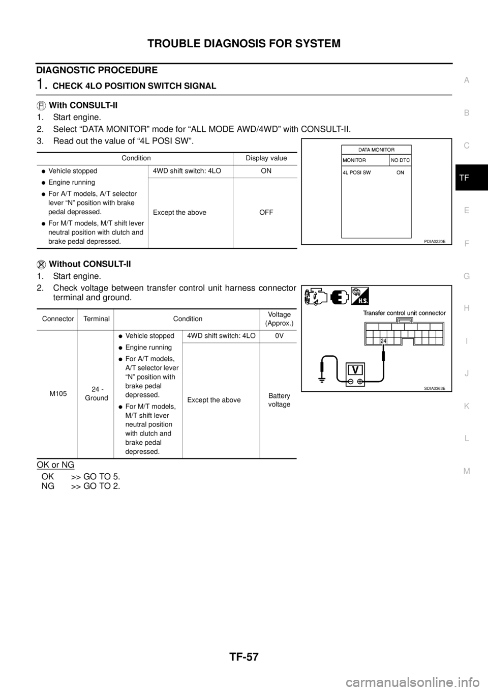
DIAGNOSTIC PROCEDURE
1.CHECK 4LO POSITION SWITCH SIGNAL
With CONSULT-II
1. Start engine.
2. Select “DATA MONITOR” mode for “ALL MODE AWD/4WD” with CONSULT-II.
3. Read out the value of “4L POSI SW”.
Without CONSULT-II
1. Start engine.
2. Check voltage between transfer control unit harness connector
terminal and ground.
OK or NG
OK >> GO TO 5.
NG >> GO TO 2.
Condition Display value
lVehicle stopped
lEngine running
lFor A/T models, A/T selector
lever “N” position with brake
pedal depressed.
lFor M/T models, M/T shift lever
neutral position with clutch and
brake pedal depressed.4WD shift switch: 4LO ON
Except the above OFF
PDIA0220E
Connector Terminal ConditionVo l ta g e
(Approx.)
M10524 -
Ground
lVehicle stopped
lEngine running
lFor A/T models,
A/T selector lever
“N” position with
brake pedal
depressed.
lFor M/T models,
M/T shift lever
neutral position
with clutch and
brake pedal
depressed.4WD shift switch: 4LO 0V
Except the aboveBattery
voltage
SDIA3363E