2005 NISSAN NAVARA engine
[x] Cancel search: enginePage 2878 of 3171
SQUEAK AND RATTLE TROUBLE DIAGNOSES
SE-7
C
D
E
F
G
H
J
K
L
MA
B
SE
TRUNK
Trunk noises are often caused by a loose jack or loose items put into the trunk by the owner.
In addition look for:
1. Trunk lid dumpers out of adjustment
2. Trunk lid striker out of adjustment
3. Trunk lid torsion bars knocking together
4. A loose license plate or bracket
Most of these incidents can be repaired by adjusting, securing or insulating the item(s) or component(s) caus-
ing the noise.
SUNROOF/HEADLINING
Noises in the sunroof/headlining area can often be traced to one of the following:
1. Sunroof lid, rail, linkage or seals making a rattle or light knocking noise
2. Sunvisor shaft shaking in the holder
3. Front or rear windshield touching headlining and squeaking
Again, pressing on the components to stop the noise while duplicating the conditions can isolate most of these
incidents. Repairs usually consist of insulating with felt cloth tape.
SEATS
When isolating seat noise it's important to note the position the seat is in and the load placed on the seat when
the noise is present. These conditions should be duplicated when verifying and isolating the cause of the
noise.
Cause of seat noise include:
1. Headrest rods and holder
2. A squeak between the seat pad cushion and frame
3. Rear seatback lock and bracket
These noises can be isolated by moving or pressing on the suspected components while duplicating the con-
ditions under which the noise occurs. Most of these incidents can be repaired by repositioning the component
or applying urethane tape to the contact area.
UNDERHOOD
Some interior noise may be caused by components under the hood or on the engine wall. The noise is then
transmitted into the passenger compartment.
Causes of transmitted underhood noise include:
1. Any component mounted to the engine wall
2. Components that pass through the engine wall
3. Engine wall mounts and connectors
4. Loose radiator mounting pins
5. Hood bumpers out of adjustment
6. Hood striker out of adjustment
These noises can be difficult to isolate since they cannot be reached from the interior of the vehicle. The best
method is to secure, move or insulate one component at a time and test drive the vehicle. Also, engine RPM
or load can be changed to isolate the noise. Repairs can usually be made by moving, adjusting, securing, or
insulating the component causing the noise.
Page 2969 of 3171

TF-2
DIAGNOSTIC PROCEDURE .............................. 53
COMPONENT INSPECTION .............................. 54
Transfer Control Unit .............................................. 54
DIAGNOSTIC PROCEDURE .............................. 54
Output Shaft Revolution Signal (TCM) ................... 55
DIAGNOSTIC PROCEDURE .............................. 55
Vehicle Speed Sensor (ABS) .................................. 55
DIAGNOSTIC PROCEDURE .............................. 55
4LO Switch ............................................................. 56
CONSULT-II REFERENCE VALUE IN DATA
MONITOR MODE ................................................ 56
TRANSFER CONTROL UNIT TERMINALS AND
REFERENCE VALUE .......................................... 56
DIAGNOSTIC PROCEDURE .............................. 57
COMPONENT INSPECTION .............................. 59
4WD Shift Switch .................................................... 59
CONSULT-II REFERENCE VALUE IN DATA
MONITOR MODE ................................................ 59
TRANSFER CONTROL UNIT TERMINALS AND
REFERENCE VALUE .......................................... 59
DIAGNOSTIC PROCEDURE .............................. 60
COMPONENT INSPECTION .............................. 62
Wait Detection Switch ............................................. 63
CONSULT-II REFERENCE VALUE IN DATA
MONITOR MODE ................................................ 63
TRANSFER CONTROL UNIT TERMINALS AND
REFERENCE VALUE .......................................... 63
DIAGNOSTIC PROCEDURE .............................. 64
COMPONENT INSPECTION .............................. 66
PNP Switch Signal (TCM) ...................................... 66
DIAGNOSTIC PROCEDURE .............................. 66
Actuator Motor ........................................................ 67
CONSULT-II REFERENCE VALUE IN DATA
MONITOR MODE ................................................ 67
TRANSFER CONTROL UNIT TERMINALS AND
REFERENCE VALUE .......................................... 67
DIAGNOSTIC PROCEDURE .............................. 68
COMPONENT INSPECTION .............................. 74
Actuator Position Switch ......................................... 75
CONSULT-II REFERENCE VALUE IN DATA
MONITOR MODE ................................................ 75
TRANSFER CONTROL UNIT TERMINALS AND
REFERENCE VALUE .......................................... 75
DIAGNOSTIC PROCEDURE .............................. 76
Transfer Control Device .......................................... 78
CONSULT-II REFERENCE VALUE IN DATA
MONITOR MODE ................................................ 78
TRANSFER CONTROL UNIT TERMINALS AND
REFERENCE VALUE .......................................... 78
DIAGNOSTIC PROCEDURE .............................. 79
Engine Speed Signal (ECM) ................................... 81
DIAGNOSTIC PROCEDURE .............................. 81
CAN Communication Line ...................................... 82
DIAGNOSTIC PROCEDURE .............................. 82
ATP Switch ............................................................. 82
CONSULT-II REFERENCE VALUE IN DATA
MONITOR MODE ................................................ 82
TRANSFER CONTROL UNIT TERMINALS ANDREFERENCE VALUE .......................................... 82
DIAGNOSTIC PROCEDURE ............................... 83
COMPONENT INSPECTION ............................... 85
Park/Neutral Position Switch ................................... 85
TRANSFER CONTROL UNIT TERMINALS AND
REFERENCE VALUE .......................................... 85
DIAGNOSTIC PROCEDURE ............................... 85
COMPONENT INSPECTION ............................... 87
TROUBLE DIAGNOSIS FOR SYMPTOMS .............. 88
4WD Shift Indicator Lamp and 4LO Indicator Lamp
Do Not Turn ON ...................................................... 88
SYMPTOM: .......................................................... 88
DIAGNOSTIC PROCEDURE ............................... 89
4WD Warning Lamp Does Not Turn ON ................. 91
SYMPTOM: .......................................................... 91
DIAGNOSTIC PROCEDURE ............................... 92
4WD Shift Indicator Lamp or 4LO Indicator Lamp
Does Not Change ................................................... 94
SYMPTOM: .......................................................... 94
DIAGNOSTIC PROCEDURE ............................... 95
ATP Warning Lamp Does Not Turn ON .................. 96
SYMPTOM: .......................................................... 96
DIAGNOSTIC PROCEDURE ............................... 96
4WD Shift Indicator Lamp Repeats Flashing .......... 98
SYMPTOM: .......................................................... 98
DIAGNOSTIC PROCEDURE ............................... 98
4WD Warning Lamp Flashes Slowly ....................... 99
SYMPTOM: .......................................................... 99
DIAGNOSTIC PROCEDURE ............................... 99
TRANSFER CONTROL UNIT .................................100
Removal and Installation .......................................100
REMOVAL ..........................................................100
INSTALLATION ..................................................100
FRONT OIL SEAL ...................................................101
Removal and Installation .......................................101
REMOVAL ..........................................................101
INSTALLATION ..................................................102
REAR OIL SEAL .....................................................103
Removal and Installation .......................................103
REMOVAL ..........................................................103
INSTALLATION ..................................................103
TRANSFER CONTROL DEVICE ............................105
Removal and Installation .......................................105
REMOVAL ..........................................................105
INSTALLATION ..................................................105
AIR BREATHER HOSE ...........................................107
Removal and Installation .......................................107
A/T MODELS .....................................................107
M/T MODELS .....................................................109
TRANSFER ASSEMBLY ......................................... 111
Removal and Installation ....................................... 111
REMOVAL .......................................................... 111
INSTALLATION ..................................................112
Disassembly and Assembly ..................................112
COMPONENTS .................................................112
DISASSEMBLY ..................................................114
INSPECTION AFTER DISASSEMBLY ..............119
ASSEMBLY ........................................................120
Page 2971 of 3171
TF-4
PRECAUTIONS
PRECAUTIONS
PFP:00001
Precautions for Supplemental Restraint System (SRS) “AIR BAG” and “SEAT
BELT PRE-TENSIONER”
EDS003ID
The Supplemental Restraint System such as “AIR BAG” and “SEAT BELT PRE-TENSIONER”, used along
with a front seat belt, helps to reduce the risk or severity of injury to the driver and front passenger for certain
types of collision. Information necessary to service the system safely is included in the SRS and SB section of
this Service Manual.
WARNING:
lTo avoid rendering the SRS inoperative, which could increase the risk of personal injury or death
in the event of a collision which would result in air bag inflation, all maintenance must be per-
formed by an authorized NISSAN/INFINITI dealer.
lImproper maintenance, including incorrect removal and installation of the SRS, can lead to per-
sonal injury caused by unintentional activation of the system. For removal of Spiral Cable and Air
Bag Module, see the SRS section.
lDo not use electrical test equipment on any circuit related to the SRS unless instructed to in this
Service Manual. SRS wiring harnesses can be identified by yellow and/or orange harnesses or
harness connectors.
Precautions for Transfer Assembly and Transfer Control Unit ReplacementEDS0031A
lWhen replacing transfer assembly or transfer control unit, check the 4WD shift indicator pattern and
adjustment of the position between transfer assembly and transfer control unit if necessary.
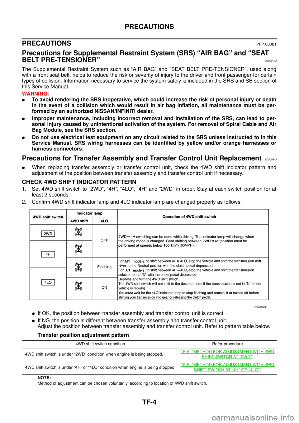
CHECK 4WD SHIFT INDICATOR PATTERN
1. Set 4WD shift switch to “2WD”, “4H”, “4LO”, “4H” and “2WD” in order. Stay at each switch position for at
least 2 seconds.
2. Confirm 4WD shift indicator lamp and 4LO indicator lamp are changed properly as follows.
lIf OK, the position between transfer assembly and transfer control unit is correct.
lIf NG, the position is different between transfer assembly and transfer control unit.
Adjust the position between transfer assembly and transfer control unit. Refer to pattern table below.
Transfer position adjustment pattern
NOTE:
Method of adjustment can be chosen voluntarily, according to location of 4WD shift switch.
SDIA3289E
4WD shift switch condition Refer procedure
4WD shift switch is under “2WD” condition when engine is being stopped.TF-5, "
METHOD FOR ADJUSTMENT WITH 4WD
SHIFT SWITCH AT“2WD”"
4WD shift switch is under “4H” or “4LO” condition when engine is being stopped.TF-5, "METHOD FOR ADJUSTMENT WITH 4WD
SHIFT SWITCH AT“4H”OR“4LO”"
Page 2972 of 3171
PRECAUTIONS
TF-5
C
E
F
G
H
I
J
K
L
MA
B
TF
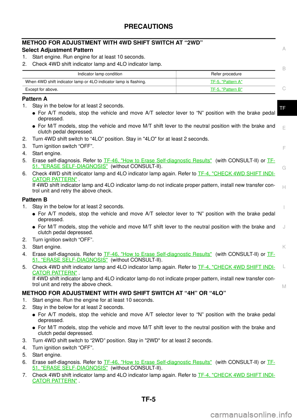
METHODFORADJUSTMENTWITH4WDSHIFTSWITCHAT“2WD”
Select Adjustment Pattern
1. Start engine. Run engine for at least 10 seconds.
2. Check 4WD shift indicator lamp and 4LO indicator lamp.
Pattern A
1. Stay in the below for at least 2 seconds.
lFor A/T models, stop the vehicle and move A/T selector lever to “N” position with the brake pedal
depressed.
lFor M/T models, stop the vehicle and move M/T shift lever to the neutral position with the brake and
clutch pedal depressed.
2. Turn 4WD shift switch to “4LO” position. Stay in "4LO" for at least 2 seconds.
3. Turn ignition switch “OFF”.
4. Start engine.
5. Erase self-diagnosis. Refer toTF-46, "
How to Erase Self-diagnostic Results"(with CONSULT-II) orTF-
51, "ERASE SELF-DIAGNOSIS"(without CONSULT-II).
6. Check 4WD shift indicator lamp and 4LO indicator lamp again. Refer toTF-4, "
CHECK 4WD SHIFT INDI-
CATOR PATTERN".
If 4WD shift indicator lamp and 4LO indicator lamp do not indicate proper pattern, install new transfer con-
trol unit and retry the above check.
Pattern B
1. Stay in the below for at least 2 seconds.
lFor A/T models, stop the vehicle and move A/T selector lever to “N” position with the brake pedal
depressed.
lFor M/T models, stop the vehicle and move M/T shift lever to the neutral position with the brake and
clutch pedal depressed.
2. Turn ignition switch “OFF”.
3. Start engine.
4. Erase self-diagnosis. Refer toTF-46, "
How to Erase Self-diagnostic Results"(with CONSULT-II) orTF-
51, "ERASE SELF-DIAGNOSIS"(without CONSULT-II).
5. Check 4WD shift indicator lamp and 4LO indicator lamp again. Refer toTF-4, "
CHECK 4WD SHIFT INDI-
CATOR PATTERN".
If 4WD shift indicator lamp and 4LO indicator lamp do not indicate proper pattern, install new transfer con-
trol unit and retry the above check.
METHODFORADJUSTMENTWITH4WDSHIFTSWITCHAT“4H”OR“4LO”
1. Start engine. Run the engine for at least 10 seconds.
2. Stay in the below for at least 2 seconds.
lFor A/T models, stop the vehicle and move A/T selector lever to “N” position with the brake pedal
depressed.
lFor M/T models, stop the vehicle and move M/T shift lever to the neutral position with the brake and
clutch pedal depressed.
3. Turn 4WD shift switch to “2WD” position. Stay in "2WD" for at least 2 seconds.
4. Turn ignition switch “OFF”.
5. Start engine.
6. Erase self-diagnosis. Refer toTF-46, "
How to Erase Self-diagnostic Results"(with CONSULT-II) orTF-
51, "ERASE SELF-DIAGNOSIS"(without CONSULT-II).
7. Check 4WD shift indicator lamp and 4LO indicator lamp again. Refer toTF-4, "
CHECK 4WD SHIFT INDI-
CATOR PATTERN".
Indicator lamp condition Refer procedure
When 4WD shift indicator lamp or 4LO indicator lamp is flashing.TF-5, "
Pattern A"
Except for above.TF-5, "Pattern B"
Page 2979 of 3171
TF-12
TRANSFER FLUID
TRANSFER FLUID
PFP:31001
ReplacementEDS0031H
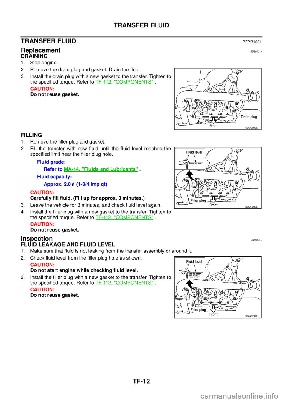
DRAINING
1. Stop engine.
2. Remove the drain plug and gasket. Drain the fluid.
3. Install the drain plug with a new gasket to the transfer. Tighten to
the specified torque. Refer toTF-112, "
COMPONENTS".
CAUTION:
Do not reuse gasket.
FILLING
1. Remove the filler plug and gasket.
2. Fill the transfer with new fluid until the fluid level reaches the
specified limit near the filler plug hole.
CAUTION:
Carefully fill fluid. (Fill up for approx. 3 minutes.)
3. Leave the vehicle for 3 minutes, and check fluid level again.
4. Install the filler plug with a new gasket to the transfer. Tighten to
the specified torque. Refer toTF-112, "
COMPONENTS".
CAUTION:
Do not reuse gasket.
InspectionEDS0031I
FLUID LEAKAGE AND FLUID LEVEL
1. Make sure that fluid is not leaking from the transfer assembly or around it.
2. Check fluid level from the filler plug hole as shown.
CAUTION:
Do not start engine while checking fluid level.
3. Install the filler plug with a new gasket to the transfer. Tighten to
the specified torque. Refer toTF-112, "
COMPONENTS".
CAUTION:
Do not reuse gasket.
SDIA3286E
Fluid grade:
Refer toMA-14, "
Fluids and Lubricants".
Fluid capacity:
Approx. 2.0 (1-3/4 Imp qt)
SDIA3287E
SDIA3287E
Page 2983 of 3171

TF-16
4WD SYSTEM
4WD SHIFT SWITCH AND INDICATOR LAMP
4WD Shift Switch
4WD shift switch is able to select from 2WD, 4H or 4LO.
4WD Shift Indicator Lamp
lDisplays driving conditions selected by 4WD shift switch with front, rear and center indicators, while
engine is running. (When shifting from 4H to 4LO, 4LO indicator lamp also turns on. And when 4WD warn-
ing lamp is turned on, all 4WD shift indicator lamps are turned off.)
lTurns ON when ignition switch is turned ON, for purpose of lamp check. Turns OFF approximately 1 sec-
ondaftertheenginestartsifsystemisnormal.
4LO Indicator Lamp
lDisplays 4LO condition while engine is running. 4LO indicator lamp flashes if transfer gear does not shift
completely under 4HÛ4LO. In this condition, transfer may be under neutral condition and A/T parking
mechanism may not operate.
lTurns ON when ignition switch is turned ON, for purpose of lamp check. Turns OFF approximately 1 sec-
ondaftertheenginestartsifsystemisnormal.
SDIA3290E
Page 2984 of 3171
4WD SYSTEM
TF-17
C
E
F
G
H
I
J
K
L
MA
B
TF
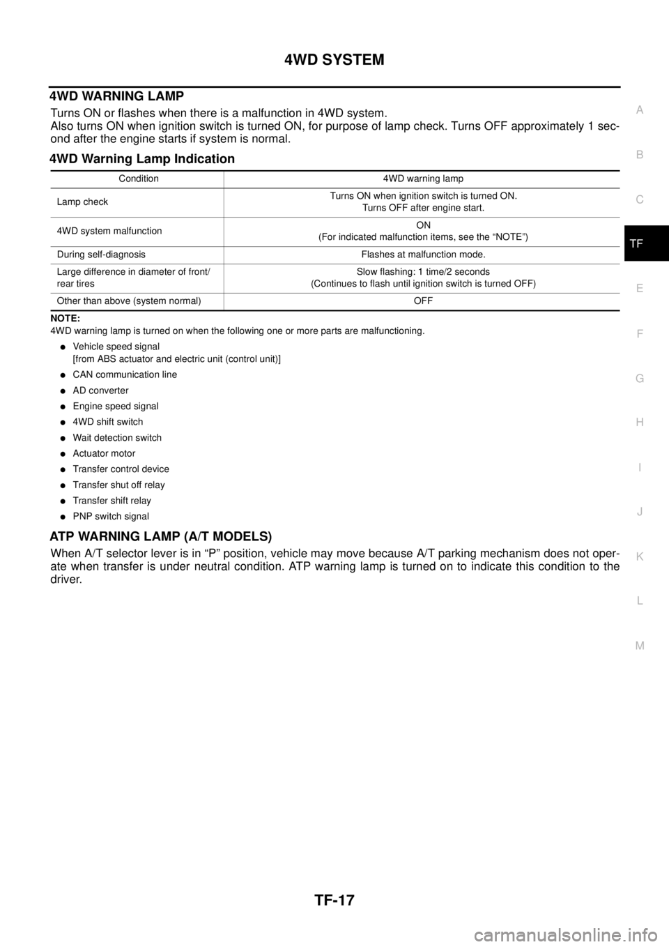
4WD WARNING LAMP
Turns ON or flashes when there is a malfunction in 4WD system.
Also turns ON when ignition switch is turned ON, for purpose of lamp check. Turns OFF approximately 1 sec-
ond after the engine starts if system is normal.
4WD Warning Lamp Indication
NOTE:
4WD warning lamp is turned on when the following one or more parts are malfunctioning.
lVehicle speed signal
[from ABS actuator and electric unit (control unit)]
lCAN communication line
lAD converter
lEngine speed signal
l4WD shift switch
lWait detection switch
lActuator motor
lTransfer control device
lTransfer shut off relay
lTransfer shift relay
lPNP switch signal
ATP WARNING LAMP (A/T MODELS)
When A/T selector lever is in “P” position, vehicle may move because A/T parking mechanism does not oper-
ate when transfer is under neutral condition. ATP warning lamp is turned on to indicate this condition to the
driver.
Condition 4WD warning lamp
Lamp checkTurns ON when ignition switch is turned ON.
Turns OFF after engine start.
4WD system malfunctionON
(For indicated malfunction items, see the “NOTE”)
During self-diagnosis Flashes at malfunction mode.
Large difference in diameter of front/
rear tiresSlow flashing: 1 time/2 seconds
(Continues to flash until ignition switch is turned OFF)
Other than above (system normal) OFF
Page 2986 of 3171
4WD SYSTEM
TF-19
C
E
F
G
H
I
J
K
L
MA
B
TF
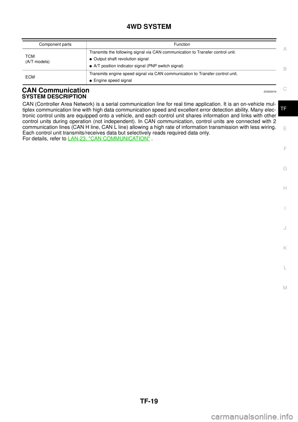
CAN CommunicationEDS0031N
SYSTEM DESCRIPTION
CAN (Controller Area Network) is a serial communication line for real time application. It is an on-vehicle mul-
tiplex communication line with high data communication speed and excellent error detection ability. Many elec-
tronic control units are equipped onto a vehicle, and each control unit shares information and links with other
control units during operation (not independent). In CAN communication, control units are connected with 2
communication lines (CAN H line, CAN L line) allowing a high rate of information transmission with less wiring.
Each control unit transmits/receives data but selectively reads required data only.
For details, refer toLAN-23, "
CAN COMMUNICATION".
TCM
(A/T models)Transmits the following signal via CAN communication to Transfer control unit.lOutput shaft revolution signal
lA/T position indicator signal (PNP switch signal)
ECMTransmits engine speed signal via CAN communication to Transfer control unit.
lEngine speed signal Component parts Function