2005 NISSAN NAVARA engine
[x] Cancel search: enginePage 2390 of 3171

MTC-3
C
D
E
F
G
H
I
K
L
MA
B
MTC BLOWER MOTOR RESISTOR ................................112
Components .......................................................... 112
Removal and Installation ....................................... 112
REMOVAL .......................................................... 112
INSTALLATION .................................................. 112
DUCTS AND GRILLES ...........................................113
Components .......................................................... 113
Removal and Installation ....................................... 116
CENTER CONSOLE HEAT DUCT AND REAR
FINISHER ASSEMBLY GRILLE ........................ 116
DEFROSTER NOZZLE ...................................... 116
RH AND LH SIDE DEMISTER DUCT ................ 116
RH AND LH VENTILATOR DUCT ...................... 116
CENTER VENTILATOR DUCT .......................... 116
FLOOR DUCT .................................................... 116
GRILLES ............................................................ 116
REFRIGERANT LINES ............................................118
HFC-134a (R-134a) Service Procedure ................ 118
SETTING OF SERVICE TOOLS AND EQUIP-
MENT ................................................................. 118
Components ......................................................... 120
Removal and Installation for Compressor ............ 122
REMOVAL ......................................................... 122
INSTALLATION ................................................. 122
Removal and Installation for Compressor Clutch . 123
REMOVAL ......................................................... 123
INSPECTION .................................................... 124
INSTALLATION ................................................. 124
BREAK-IN OPERATION ................................... 126
Removal and Installation for Low-pressure Flexible
Hose ..................................................................... 126
REMOVAL ......................................................... 126
INSTALLATION ................................................. 126
Removal and Installation for High-pressure Flexible
Hose ..................................................................... 126
REMOVAL ......................................................... 126INSTALLATION .................................................126
Removal and Installation for High-pressure Pipe . 126
REMOVAL .........................................................126
INSTALLATION .................................................126
Removal and Installation for Low-pressure Pipe ..127
REMOVAL .........................................................127
INSTALLATION .................................................127
Removal and Installation for Refrigerant Pressure
Sensor ..................................................................127
REMOVAL .........................................................127
INSTALLATION .................................................127
Removal and Installation for Condenser ..............127
REMOVAL .........................................................127
INSTALLATION .................................................128
Removal and Installation for Evaporator ..............129
REMOVAL .........................................................130
INSTALLATION .................................................130
Removal and Installation for Expansion Valve ......130
REMOVAL .........................................................130
INSTALLATION .................................................130
Checking for Refrigerant Leaks ............................131
Checking System for Leaks Using the Fluorescent
Leak Detector .......................................................131
Dye Injection .........................................................131
Electronic Refrigerant Leak Detector ....................132
PRECAUTIONS FOR HANDLING LEAK
DETECTOR .......................................................132
CHECKING PROCEDURE ...............................133
SERVICE DATA AND SPECIFICATIONS (SDS) ....135
Service Data and Specifications (SDS) ................135
COMPRESSOR ................................................135
LUBRICANT ......................................................135
REFRIGERANT .................................................135
ENGINE IDLING SPEED ..................................135
BELT TENSION .................................................135
Page 2399 of 3171
MTC-12
PRECAUTIONS
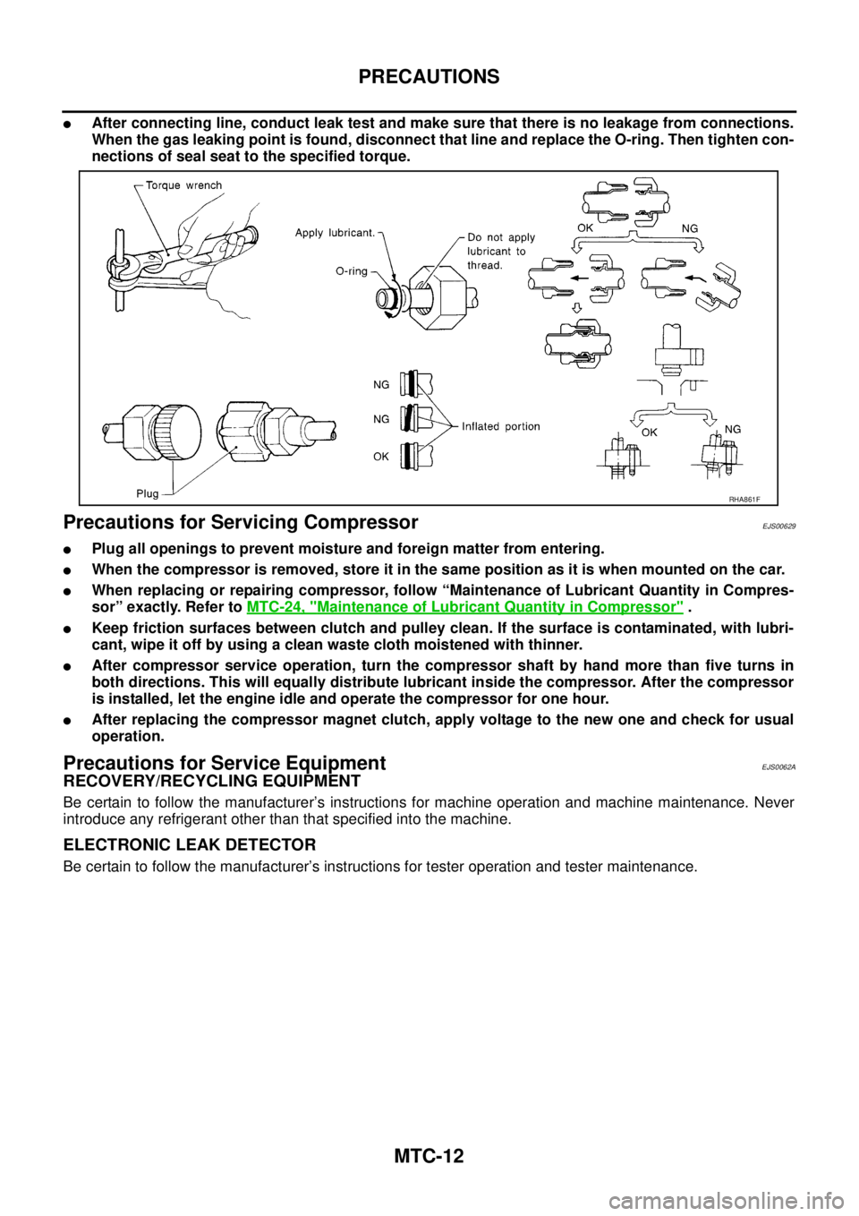
lAfter connecting line, conduct leak test and make sure that there is no leakage from connections.
When the gas leaking point is found, disconnect that line and replace the O-ring. Then tighten con-
nections of seal seat to the specified torque.
Precautions for Servicing CompressorEJS00629
lPlug all openings to prevent moisture and foreign matter from entering.
lWhen the compressor is removed, store it in the same position as it is when mounted on the car.
lWhen replacing or repairing compressor, follow “Maintenance of Lubricant Quantity in Compres-
sor” exactly. Refer toMTC-24, "
Maintenance of Lubricant Quantity in Compressor".
lKeep friction surfaces between clutch and pulley clean. If the surface is contaminated, with lubri-
cant, wipe it off by using a clean waste cloth moistened with thinner.
lAfter compressor service operation, turn the compressor shaft by hand more than five turns in
both directions. This will equally distribute lubricant inside the compressor. After the compressor
is installed, let the engine idle and operate the compressor for one hour.
lAfter replacing the compressor magnet clutch, apply voltage to the new one and check for usual
operation.
Precautions for Service EquipmentEJS0062A
RECOVERY/RECYCLING EQUIPMENT
Be certain to follow the manufacturer’s instructions for machine operation and machine maintenance. Never
introduce any refrigerant other than that specified into the machine.
ELECTRONIC LEAK DETECTOR
Be certain to follow the manufacturer’s instructions for tester operation and tester maintenance.
RHA861F
Page 2402 of 3171
PRECAUTIONS
MTC-15
C
D
E
F
G
H
I
K
L
MA
B
MTC
lA compressor shaft seal should not be repaired because of dye seepage. The compressor shaft seal
should only be repaired after confirming the leak with an electronic refrigerant leak detector (J-41995).
lAlways remove any remaining dye from the leak area after repairs are complete to avoid a misdiagnosis
during a future service.
lDo not allow dye to come into contact with painted body panels or interior components. If dye is spilled,
clean immediately with the approved dye cleaner. Fluorescent dye left on a surface for an extended period
of time cannot be removed.
lDo not spray the fluorescent dye cleaning agent on hot surfaces (engine exhaust manifold, etc.).
lDo not use more than one refrigerant dye bottle (1/4 ounce /7.4 cc) per A/C system.
lLeak detection dyes for HFC-134a (R-134a) and CFC-12 (R-12) A/C systems are different. Do not use
HFC-134a (R-134a) leak detection dye in CFC-12 (R-12) A/C system or CFC-12 (R-12) leak detector dye
in HFC-134a (R-134a) A/C systems or A/C system damage may result.
lThe fluorescent properties of the dye will remain for over three (3) years unless a compressor malfunction
occurs.
IDENTIFICATION
NOTE:
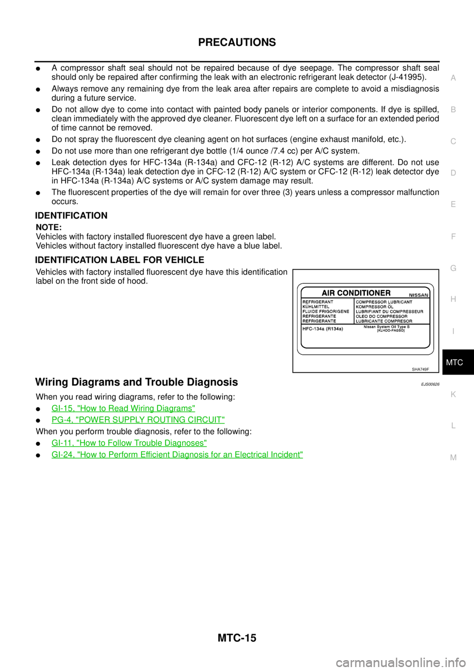
Vehicles with factory installed fluorescent dye have a green label.
Vehicles without factory installed fluorescent dye have a blue label.
IDENTIFICATION LABEL FOR VEHICLE
Vehicles with factory installed fluorescent dye have this identification
label on the front side of hood.
Wiring Diagrams and Trouble DiagnosisEJS00626
When you read wiring diagrams, refer to the following:
lGI-15, "How to Read Wiring Diagrams"
lPG-4, "POWER SUPPLY ROUTING CIRCUIT"
When you perform trouble diagnosis, refer to the following:
lGI-11, "How to Follow Trouble Diagnoses"
lGI-24, "How to Perform Efficient Diagnosis for an Electrical Incident"
SHA749F
Page 2411 of 3171
MTC-24
LUBRICANT
LUBRICANT
PFP:KLG00
Maintenance of Lubricant Quantity in CompressorEJS005FV
The lubricant in the compressor circulates through the system with the refrigerant. Add lubricant to compres-
sor when replacing any component or after a large refrigerant leakage has occurred. It is important to maintain
the specified amount.
If lubricant quantity is not maintained properly, the following malfunctions may result:
lLack of lubricant: May lead to a seized compressor
lExcessive lubricant: Inadequate cooling (thermal exchange interference)
LUBRICANT
Name: NISSAN A/C System Lubricant Type S (DH-PS)
Part number: KLH00-PAGS0
CHECKING AND ADJUSTING
CAUTION:
If excessive lubricant leakage is noted, do not perform the lubricant return operation.
Start the engine and set the following conditions:
test condition
lEngine speed: Idling to 1,200 rpm
lA/C switch: On
lBlower speed: Max. position
lTemp. control: Optional [Set so that intake air temperature is 25°to 30°C(77°to 86°F).]
lIntake position: Recirculation ( )
lPerform lubricant return operation for about ten minutes
Adjust the lubricant quantity according to the following table.
Lubricant Adjusting Procedure for Components Replacement Except Compressor
After replacing any of the following major components, add the correct amount of lubricant to the system.
Amount of lubricant to be added
l*1: If refrigerant leak is small, no addition of lubricant is needed.
Lubricant Adjustment Procedure for Compressor Replacement
1. Before connecting recovery/recycling equipment to vehicle, check recovery/recycling equipment gauges.
No refrigerant pressure should be displayed. If NG, recover refrigerant from equipment lines.
2. Discharge refrigerant into the refrigerant recovery/recycling equipment. Measure lubricant discharged into
the recovery/recycling equipment.
3. Drain the lubricant from the “old” (removed) compressor into a graduated container and recover the
amount of lubricant drained.
4. Drain the lubricant from the “new” compressor into a separate, clean container.
5. Measure an amount of new lubricant installed equal to amount drained from “old” compressor. Add this
lubricant to “new” compressor through the suction port opening.
6. Measure an amount of new lubricant equal to the amount recovered during discharging. Add this lubricant
to “new” compressor through the suction port opening.
7. If the liquid tank also needs to be replaced, add an additional 5 m (0.2 Imp fl oz) of lubricant at this time.
Do not add this 5 m (0.2 Imp fl oz) of lubricant if only replacing the compressor.
Part replacedLubricant to be added to system
Remarks
Amount of lubricant
m(Impfloz)
Evaporator 75 (2.6) —
Condenser 75 (2.6) —
Liquid tank 5 (0.2) Add if compressor is not replaced.
In case of refrigerant leak30 (1.1) Large leak
— Small leak *1
Page 2413 of 3171

MTC-26
AIR CONDITIONER CONTROL
AIR CONDITIONER CONTROL
PFP:27500
DescriptionEJS005FW
The front air control provides regulation of the vehicle's interior temperature. The system is based on the posi-
tion of the front air controls temperature switch selected by the driver. This is done by utilizing a microcom-
puter, also referred to as the front air control, which receives input signals from the following three sensors:
lIntake sensor
lPBR (Position Balanced Resistor).
The front air control uses these signals (including the set position of the temperature switch) to control:
lOutlet air volume
lAir temperature
lAir distribution
The front air control is used to select:
lOutlet air volume
lAir temperature/distribution
OperationEJS005FX
AIR MIX DOOR CONTROL
The air mix door is controlled so that in-vehicle temperature changed based on the position of the temperature
switch.
BLOWER SPEED CONTROL
Blower speed is controlled based on front blower switch settings.
When blower switch is turned, the blower motor starts and increases air flow volume each time the blower
switch is turned counterclockwise, and decreases air flow volume each time the blower switch is turned coun-
terclockwise.
When engine coolant temperature is low, the blower motor operation is delayed to prevent cool air from flow-
ing.
INTAKE DOORS CONTROL
The intake doors are controlled by the recirculation switch setting, and the mode (defroster) switch setting.
MODE DOOR CONTROL
The mode door is controlled by the position of the mode switch.
DEFROSTER DOOR CONTROL
The defroster door is controlled by: Turning the defroster dial to front defroster.
Page 2423 of 3171
MTC-36
TROUBLE DIAGNOSIS
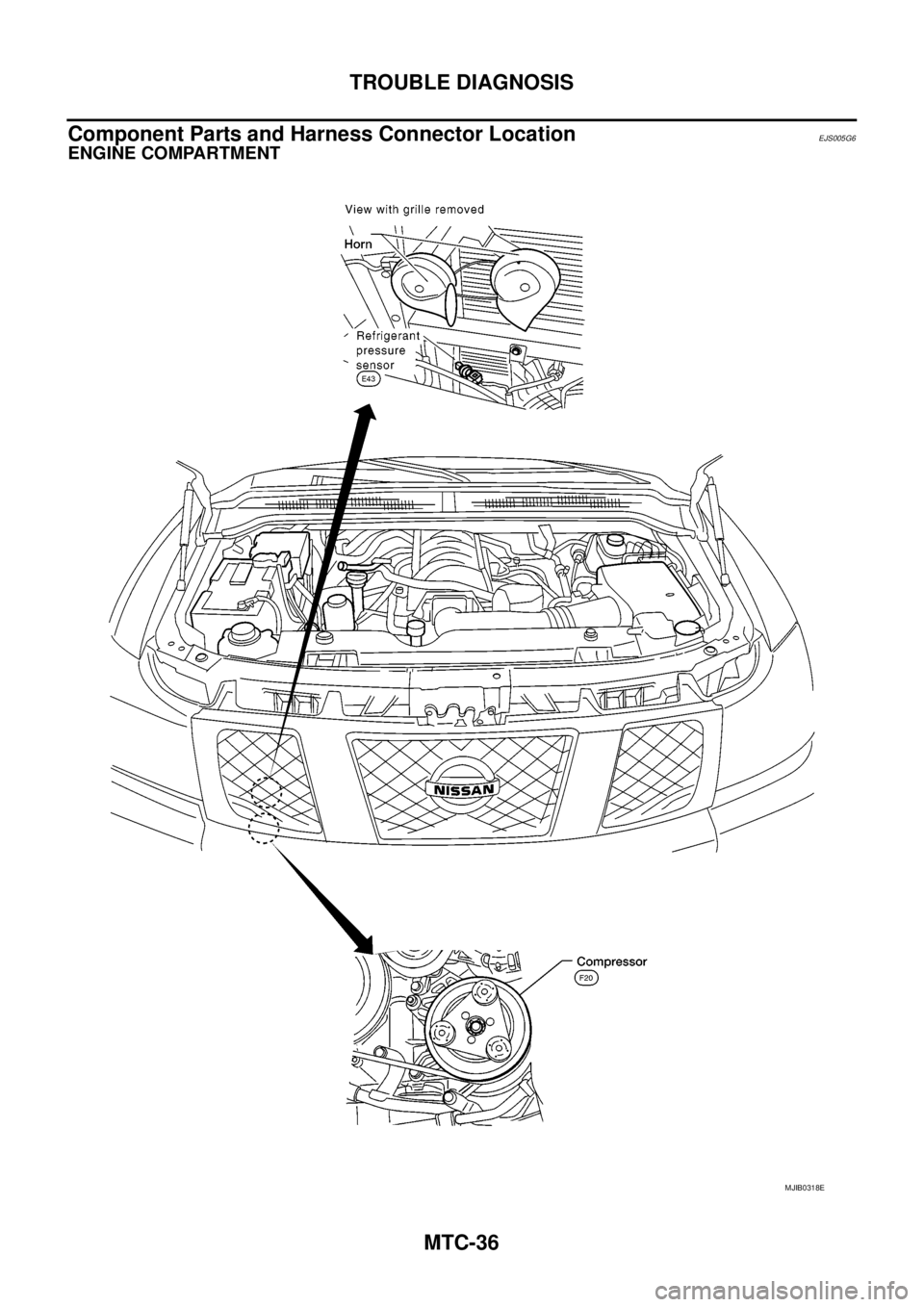
Component Parts and Harness Connector Location
EJS005G6
ENGINE COMPARTMENT
MJIB0318E
Page 2440 of 3171
TROUBLE DIAGNOSIS
MTC-53
C
D
E
F
G
H
I
K
L
MA
B
MTC
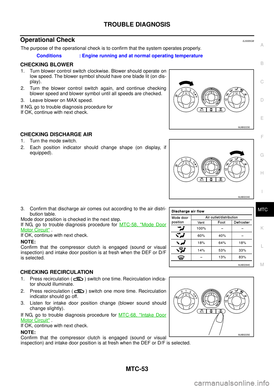
Operational CheckEJS005GB
The purpose of the operational check is to confirm that the system operates properly.
CHECKING BLOWER
1. Turn blower control switch clockwise. Blower should operate on
low speed. The blower symbol should have one blade lit (on dis-
play).
2. Turn the blower control switch again, and continue checking
blower speed and blower symbol until all speeds are checked.
3. Leave blower on MAX speed.
If NG, go to trouble diagnosis procedure for
If OK, continue with next check.
CHECKING DISCHARGE AIR
1. Turn the mode switch.
2. Each position indicator should change shape (on display, if
equipped).
3. Confirm that discharge air comes out according to the air distri-
bution table.
Mode door position is checked in the next step.
If NG, go to trouble diagnosis procedure forMTC-58, "
Mode Door
Motor Circuit".
If OK, continue with next check.
NOTE:
Confirm that the compressor clutch is engaged (sound or visual
inspection) and intake door position is at fresh when the DEF or D/F
is selected.
CHECKING RECIRCULATION
1. Press recirculation ( ) switch one time. Recirculation indica-
tor should illuminate.
2. Press recirculation ( ) switch one more time. Recirculation
indicator should go off.
3. Listen for intake door position change (blower sound should
change slightly).
If NG, go to trouble diagnosis procedure forMTC-68, "
Intake Door
Motor Circuit".
If OK, continue with next check.
NOTE:
Confirm that the compressor clutch is engaged (sound or visual
inspection) and intake door position is at fresh when the DEF or D/F is selected.Conditions : Engine running and at normal operating temperature
MJIB0223E
MJIB0224E
MJIB0284E
MJIB0225E
Page 2470 of 3171
TROUBLE DIAGNOSIS
MTC-83
C
D
E
F
G
H
I
K
L
MA
B
MTC
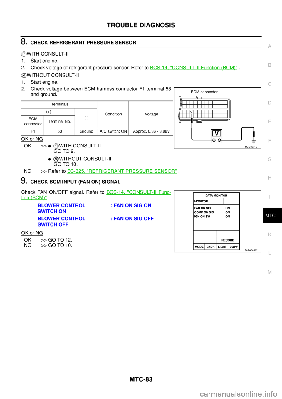
8.CHECK REFRIGERANT PRESSURE SENSOR
WITH CONSULT-II
1. Start engine.
2. Check voltage of refrigerant pressure sensor. Refer toBCS-14, "
CONSULT-II Function (BCM)".
WITHOUT CONSULT-II
1. Start engine.
2. Check voltage between ECM harness connector F1 terminal 53
and ground.
OK or NG
OK >>lWITH CONSULT-II
GO TO 9.
lWITHOUT CONSULT-II
GO TO 10.
NG >> Refer toEC-325, "
REFRIGERANT PRESSURE SENSOR".
9.CHECK BCM INPUT (FAN ON) SIGNAL
Check FAN ON/OFF signal. Refer toBCS-14, "
CONSULT-II Func-
tion (BCM)".
OK or NG
OK >> GO TO 12.
NG >> GO TO 10.
Terminals
Condition Voltage (+)
(-)
ECM
connectorTerminal No.
F1 53 Ground A/C switch: ON Approx. 0.36 - 3.88V
MJIB0071E
BLOWER CONTROL
SWITCH ON: FAN ON SIG ON
BLOWER CONTROL
SWITCH OFF:FANONSIGOFF
WJIA0469E