2005 NISSAN NAVARA engine
[x] Cancel search: enginePage 2310 of 3171
CHASSIS AND BODY MAINTENANCE
MA-35
C
D
E
F
G
H
I
J
K
MA
B
MA
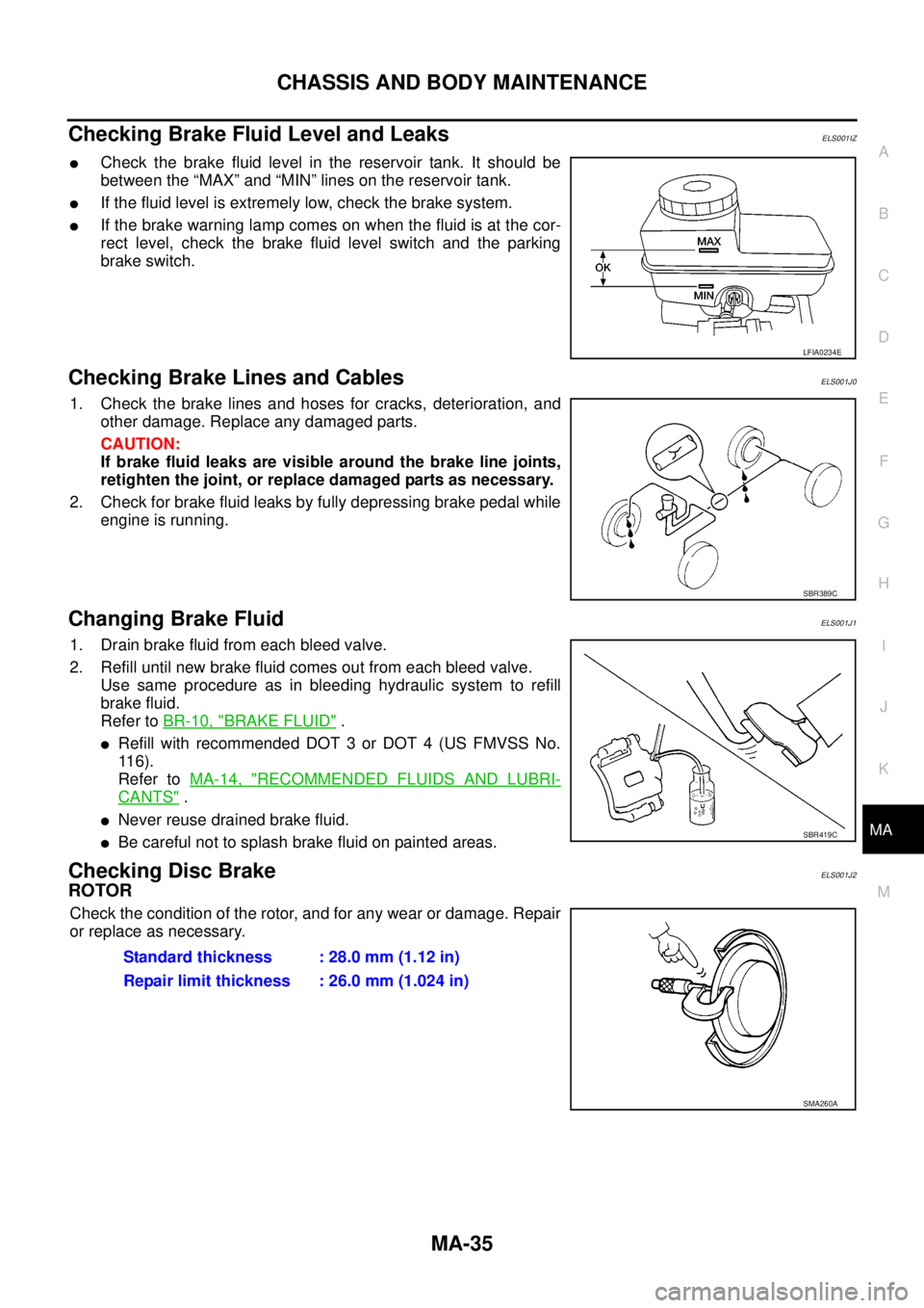
Checking Brake Fluid Level and LeaksELS001IZ
lCheck the brake fluid level in the reservoir tank. It should be
between the “MAX” and “MIN” lines on the reservoir tank.
lIf the fluid level is extremely low, check the brake system.
lIf the brake warning lamp comes on when the fluid is at the cor-
rect level, check the brake fluid level switch and the parking
brake switch.
Checking Brake Lines and CablesELS001J0
1. Check the brake lines and hoses for cracks, deterioration, and
other damage. Replace any damaged parts.
CAUTION:
If brake fluid leaks are visible around the brake line joints,
retighten the joint, or replace damaged parts as necessary.
2. Check for brake fluid leaks by fully depressing brake pedal while
engine is running.
Changing Brake FluidELS001J1
1. Drain brake fluid from each bleed valve.
2. Refill until new brake fluid comes out from each bleed valve.
Use same procedure as in bleeding hydraulic system to refill
brake fluid.
Refer toBR-10, "
BRAKE FLUID".
lRefill with recommended DOT 3 or DOT 4 (US FMVSS No.
11 6 ) .
Refer toMA-14, "
RECOMMENDED FLUIDS AND LUBRI-
CANTS".
lNever reuse drained brake fluid.
lBe careful not to splash brake fluid on painted areas.
Checking Disc BrakeELS001J2
ROTOR
Check the condition of the rotor, and for any wear or damage. Repair
or replace as necessary.
LFIA0234E
SBR389C
SBR419C
Standard thickness : 28.0 mm (1.12 in)
Repair limit thickness : 26.0 mm (1.024 in)
SMA260A
Page 2312 of 3171
CHASSIS AND BODY MAINTENANCE
MA-37
C
D
E
F
G
H
I
J
K
MA
B
MA
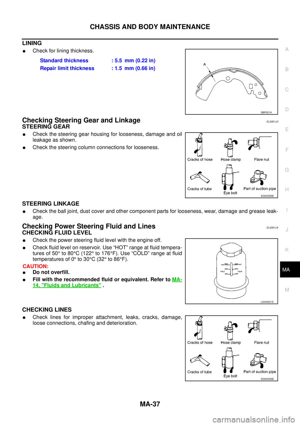
LINING
lCheck for lining thickness.
Checking Steering Gear and LinkageELS001J3
STEERING GEAR
lCheck the steering gear housing for looseness, damage and oil
leakage as shown.
lCheck the steering column connections for looseness.
STEERING LINKAGE
lCheck the ball joint, dust cover and other component parts for looseness, wear, damage and grease leak-
age.
Checking Power Steering Fluid and LinesELS001J4
CHECKING FLUID LEVEL
lCheck the power steering fluid level with the engine off.
lCheck fluid level on reservoir. Use “HOT” range at fluid tempera-
tures of 50°to 80°C(122°to 176°F). Use “COLD” range at fluid
temperatures of 0°to 30°C(32°to 86°F).
CAUTION:
lDo not overfill.
lFill with the recommended fluid or equivalent. Refer toMA-
14, "Fluids and Lubricants".
CHECKING LINES
lCheck lines for improper attachment, leaks, cracks, damage,
loose connections, chafing and deterioration.Standard thickness : 5.5 mm (0.22 in)
Repair limit thickness : 1.5 mm (0.66 in)
SBR021A
SGIA0506E
LGIA0021E
SGIA0506E
Page 2315 of 3171
MA-40
CHASSIS AND BODY MAINTENANCE
Checking Seat Belts, Buckles, Retractors, Anchors and Adjusters
ELS001J7
Check the seat belt buckles, webbing, retractors, anchors and adjusters. Replace any seat belt assembly as
necessary. Refer toSB-11, "
Seat Belt Inspection".
lCheck the seat belt anchors for loose mounting bolts, damage, or excessive wear.
lCheck the seat belt webbing for any damage, cuts, fraying, or excessive wear.
lCheck the retractor for smooth operation.
lCheck the function of the buckles by inserting the seat belt tongue and checking for proper engagement of
the buckle and press the button on the buckle to check for proper release of the seat belt tongue.
CAUTION:
lAfter any collision, inspect all seat belt assemblies, including retractors and other attached com-
ponents, such as the guide rail set. NISSAN recommends replacing all seat belt assemblies in use
during a collision, unless they are not damaged and are inspected to confirm they are operating
properly after a minor collision.
Also inspect all seat belt assemblies that are not in use during a collision, and replace any compo-
nents if damaged or not operating properly. The seat belt pre-tensioner should be replaced even if
the seat belts are not in use during a frontal collision where the driver and passenger air bags
have been deployed.
lIf any component of the seat belt assembly is suspected of being damaged or not operating prop-
erly, do not repair the component. Replace the components as an assembly.
lIf the seat belt webbing is cut, frayed, or damaged then replace the seat belt assembly.
lNever lubricate the seat belt buckle or tongue.
lWhen replacing any seat belt assembly always use a Genuine NISSAN seat belt assembly.
Checking Body CorrosionELS001K3
Visually check body panels for collision damage (scratches, chipping, rubbing, etc.) or damage to the anti-cor-
rosion materials. In particular, check the following locations.
HEMMED PANELS
Hood front end, door lower end, trunk lid rear end, etc.
PANEL JOINT
Side sill of rear fender and center pillar, rear wheel housing of rear fender, around strut tower in engine com-
partment, etc.
PANEL EDGE
Trunk lid opening, sunroof opening, fender wheel-arch flange, fuel filler lid flange, around holes in panel, etc.
PARTS CONTACT
Waist moulding, windshield moulding, bumper, etc.
PROTECTORS
Damage or condition of mudguard, fender protector, chipping protector, etc.
ANTI-CORROSION MATERIALS
Damage or separation of anti-corrosion materials under the body.
DRAIN HOLES
Condition of drain holes at door and side sill. When repairing corroded areas, refer to the Corrosion Repair
Manual.
Page 2316 of 3171
SERVICE DATA AND SPECIFICATIONS (SDS)
MA-41
C
D
E
F
G
H
I
J
K
MA
B
MA
SERVICE DATA AND SPECIFICATIONS (SDS)PFP:00030
Standard and LimitELS001J8
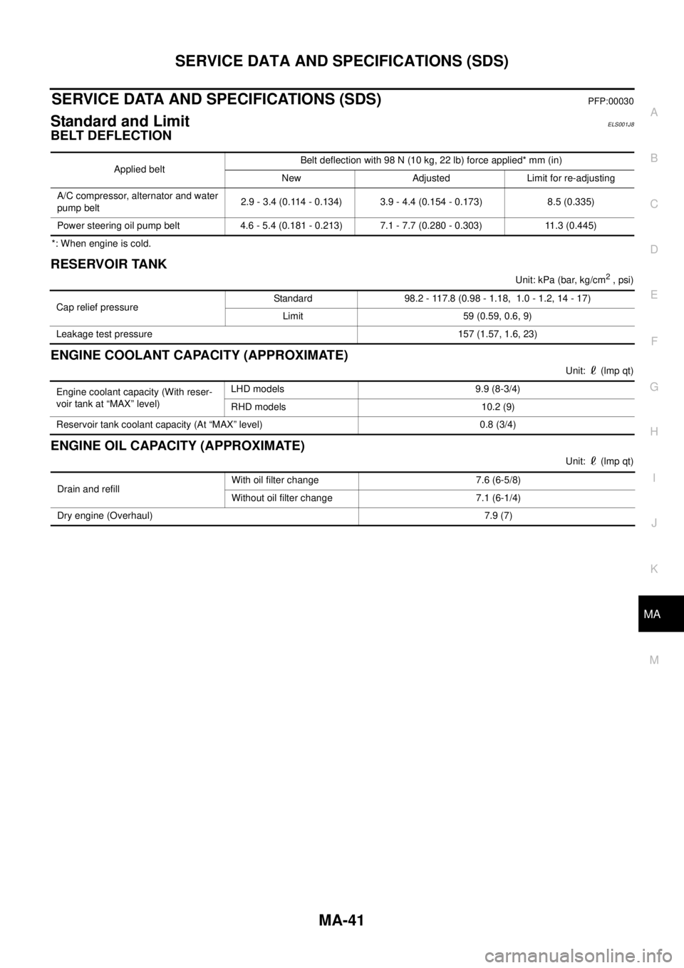
BELT DEFLECTION
*: When engine is cold.
RESERVOIR TANK
Unit:kPa(bar,kg/cm2, psi)
ENGINE COOLANT CAPACITY (APPROXIMATE)
Unit: (lmp qt)
ENGINE OIL CAPACITY (APPROXIMATE)
Unit: (lmp qt) Applied beltBelt deflection with 98 N (10 kg, 22 lb) force applied* mm (in)
New Adjusted Limit for re-adjusting
A/C compressor, alternator and water
pump belt2.9 - 3.4 (0.114 - 0.134) 3.9 - 4.4 (0.154 - 0.173) 8.5 (0.335)
Power steering oil pump belt 4.6 - 5.4 (0.181 - 0.213) 7.1 - 7.7 (0.280 - 0.303) 11.3 (0.445)
Cap relief pressureStandard 98.2 - 117.8 (0.98 - 1.18, 1.0 - 1.2, 14 - 17)
Limit 59 (0.59, 0.6, 9)
Leakage test pressure 157 (1.57, 1.6, 23)
Engine coolant capacity (With reser-
voir tank at “MAX” level)LHD models 9.9 (8-3/4)
RHD models 10.2 (9)
Reservoir tank coolant capacity (At “MAX” level) 0.8 (3/4)
Drain and refillWith oil filter change 7.6 (6-5/8)
Without oil filter change 7.1 (6-1/4)
Dry engine (Overhaul)7.9 (7)
Page 2326 of 3171

M/T OIL
MT-9
D
E
F
G
H
I
J
K
L
MA
B
MT
M/T OILPFP:KLD20
Changing M/T OilECS00ID3
DRAINING
1. Start engine and let it run to warm up transmission.
2. Stop engine. Remove drain plug and gasket and then drain oil.
3. Set a gasket on drain plug and install it to transmission case. Tighten drain plug to the specified torque.
Refer toMT-19, "
Case Components".
CAUTION:
Do no reuse gasket.
FILLING
1. Remove filler plug and gasket. Fill with new oil until oil level reaches the specified limit near filler plug
mounting hole.
2. After refilling oil, check oil level. Set a gasket to filler plug, then install it to transmission case. Tighten filler
plug to the specified torque. Refer toMT-19, "
Case Components".
CAUTION:
Do no reuse gasket.
Checking M/T OilECS00ID4
OIL LEAKAGE AND OIL LEVEL
lMake sure that oil is not leaking from transmission or around it.
lCheck oil level from filler plug mounting hole as shown in the fig-
ure.
CAUTION:
Do not start engine while checking oil level.
lSet a gasket on filler plug and install it to transmission case.
Tighten filler plug to the specified torque. Refer toMT-19, "
Case
Components".
CAUTION:
Do not reuse gasket.Oil grade and viscosity: Refer toMA-14, "
Fluids and Lubricants".
Oil capacity
2WD models:
Approx. 3.99 (7 Imp pt)
4WD models:
Approx. 4.32 (7-5/8 Imp pt)
PCIB0268E
Page 2334 of 3171
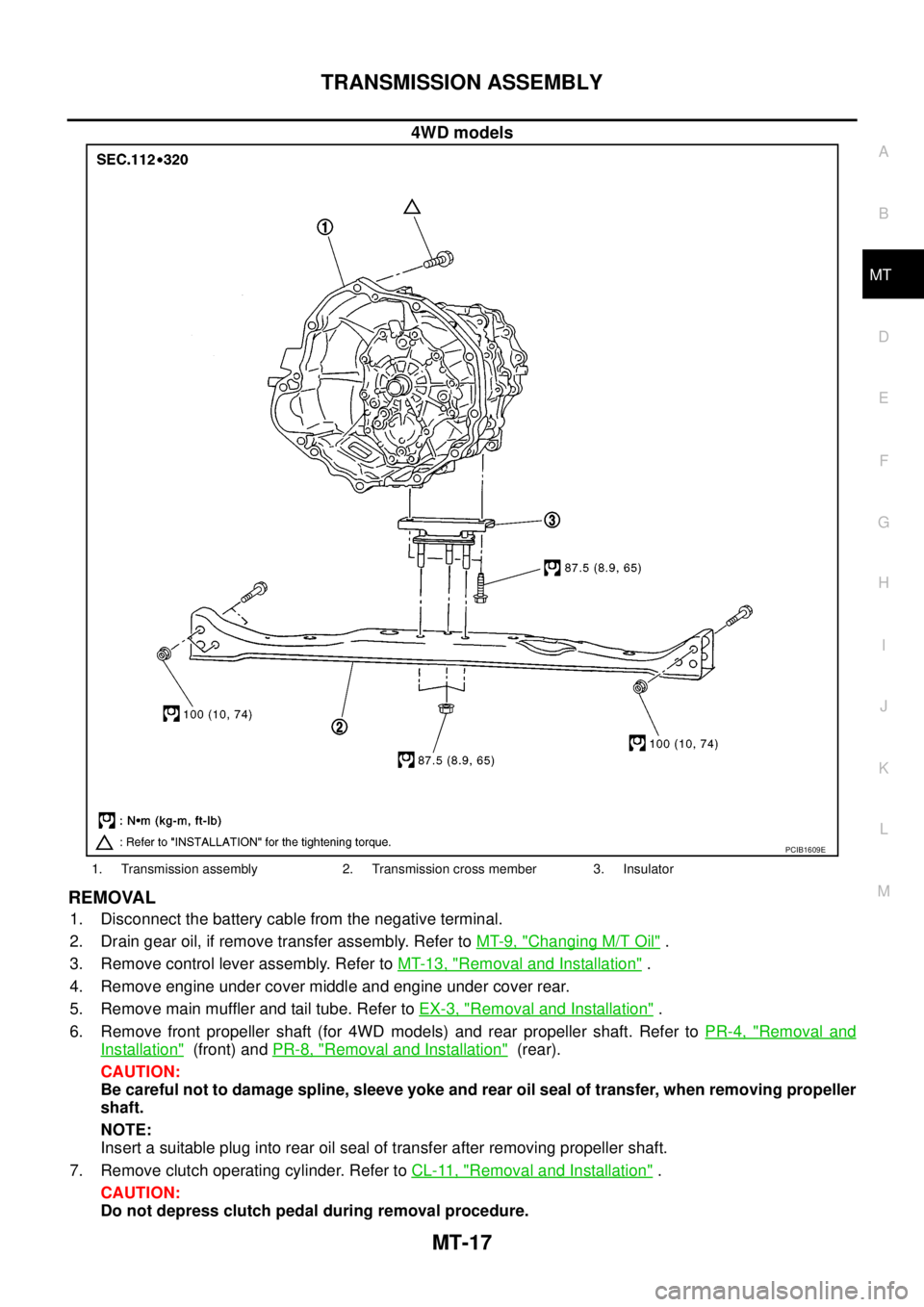
TRANSMISSION ASSEMBLY
MT-17
D
E
F
G
H
I
J
K
L
MA
B
MT
4WD models
REMOVAL
1. Disconnect the battery cable from the negative terminal.
2. Drain gear oil, if remove transfer assembly. Refer toMT-9, "
Changing M/T Oil".
3. Remove control lever assembly. Refer toMT-13, "
Removal and Installation".
4. Remove engine under cover middle and engine under cover rear.
5. Remove main muffler and tail tube. Refer toEX-3, "
Removal and Installation".
6. Remove front propeller shaft (for 4WD models) and rear propeller shaft. Refer toPR-4, "
Removal and
Installation"(front) andPR-8, "Removal and Installation"(rear).
CAUTION:
Be careful not to damage spline, sleeve yoke and rear oil seal of transfer, when removing propeller
shaft.
NOTE:
Insert a suitable plug into rear oil seal of transfer after removing propeller shaft.
7. Remove clutch operating cylinder. Refer toCL-11, "
Removal and Installation".
CAUTION:
Do not depress clutch pedal during removal procedure.
PCIB1609E
1. Transmission assembly 2. Transmission cross member 3. Insulator
Page 2384 of 3171
SERVICE DATA AND SPECIFICATIONS (SDS)
MT-67
D
E
F
G
H
I
J
K
L
MA
B
MT
SERVICE DATA AND SPECIFICATIONS (SDS)PFP:00030
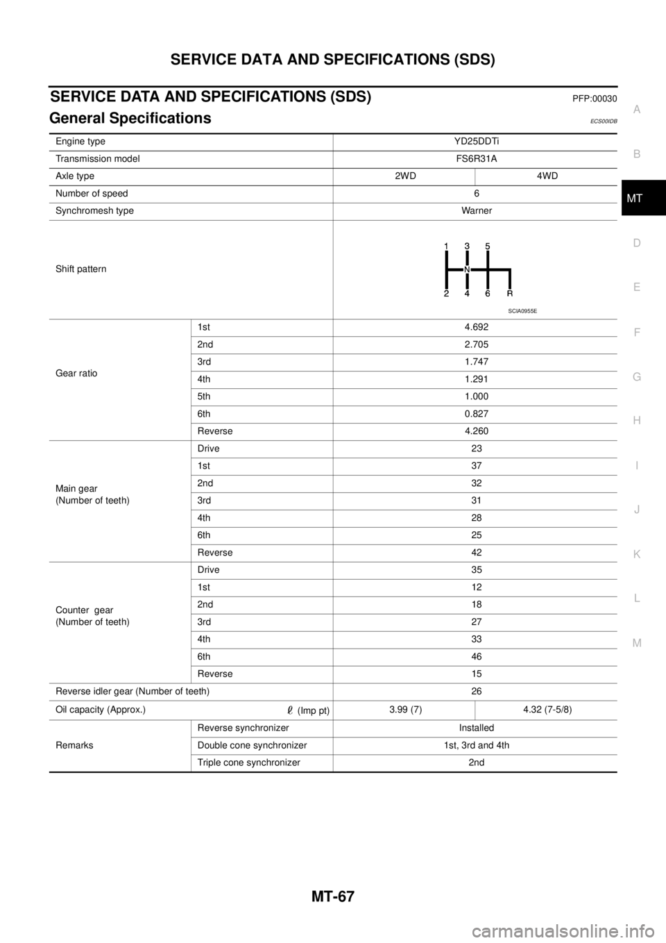
General SpecificationsECS00IDB
Engine typeYD25DDTi
Transmission modelFS6R31A
Axle type 2WD 4WD
Number of speed6
Synchromesh typeWarner
Shift pattern
Gear ratio1st 4.692
2nd 2.705
3rd 1.747
4th 1.291
5th 1.000
6th 0.827
Reverse 4.260
Main gear
(Number of teeth)Drive 23
1st 37
2nd 32
3rd 31
4th 28
6th 25
Reverse 42
Counter gear
(Number of teeth)Drive 35
1st 12
2nd 18
3rd 27
4th 33
6th 46
Reverse 15
Reverse idler gear (Number of teeth) 26
Oil capacity (Approx.)
(Imp pt)3.99 (7) 4.32 (7-5/8)
RemarksReverse synchronizer Installed
Double cone synchronizer 1st, 3rd and 4th
Triple cone synchronizer 2nd
SCIA0955E
Page 2388 of 3171
MTC-1
MANUAL AIR CONDITIONER
J AIR CONDITIONER
CONTENTS
C
D
E
F
G
H
I
K
L
M
SECTIONMTC
A
B
MTC
MANUAL AIR CONDITIONER
PRECAUTIONS .......................................................... 4
Precautions for Supplemental Restraint System
(SRS)“AIRBAG”and“SEATBELTPRE-TEN-
SIONER” .................................................................. 4
Precautions for Working with HFC-134a (R-134a)..... 4
Contaminated Refrigerant ........................................ 4
General Refrigerant Precautions .............................. 5
Precautions for Refrigerant Connection ................... 5
ABOUT ONE-TOUCH JOINT ................................ 5
FEATURES OF NEW TYPE REFRIGERANT
CONNECTION ...................................................... 7
O-RING AND REFRIGERANT CONNECTION..... 9
Precautions for Servicing Compressor ................... 12
Precautions for Service Equipment ........................ 12
RECOVERY/RECYCLING EQUIPMENT ............ 12
ELECTRONIC LEAK DETECTOR ...................... 12
VACUUM PUMP ................................................. 13
MANIFOLD GAUGE SET .................................... 13
SERVICE HOSES ............................................... 13
SERVICE COUPLERS ........................................ 14
REFRIGERANT WEIGHT SCALE ...................... 14
CALIBRATING ACR4 WEIGHT SCALE .............. 14
CHARGING CYLINDER ...................................... 14
Precautions for Leak Detection Dye ....................... 14
IDENTIFICATION ................................................ 15
IDENTIFICATION LABEL FOR VEHICLE ........... 15
Wiring Diagrams and Trouble Diagnosis ................ 15
PREPARATION ......................................................... 16
Special Service Tools ............................................. 16
HFC-134a (R-134a) Service Tools and Equipment... 16
Commercial Service Tools ...................................... 19
REFRIGERATION SYSTEM ..................................... 20
Refrigerant Cycle ................................................... 20
REFRIGERANT FLOW ....................................... 20
FREEZE PROTECTION ..................................... 20
Refrigerant System Protection ............................... 20
REFRIGERANT PRESSURE SENSOR ............. 20
PRESSURE RELIEF VALVE ............................... 21
Component Layout ................................................. 22
REFRIGERATION SYSTEM ............................... 22LUBRICANT .............................................................. 24
Maintenance of Lubricant Quantity in Compressor... 24
LUBRICANT ........................................................ 24
CHECKING AND ADJUSTING ............................ 24
AIR CONDITIONER CONTROL ............................... 26
Description .............................................................. 26
Operation ................................................................ 26
AIR MIX DOOR CONTROL ................................. 26
BLOWER SPEED CONTROL ............................. 26
INTAKE DOORS CONTROL ............................... 26
MODE DOOR CONTROL ................................... 26
DEFROSTER DOOR CONTROL ........................ 26
MAGNET CLUTCH CONTROL ........................... 27
SELF-DIAGNOSTIC SYSTEM ............................ 27
Description of Control System ................................ 28
Control Operation ................................................... 28
DISPLAY SCREEN .............................................. 29
TEMPERATURE SWITCH (TEMPERATURE
CONTROL) (FRONT) .......................................... 29
RECIRCULATION () SWITCH ............................. 29
REAR WINDOW DEFOGGER SWITCH ............. 29
OFF SWITCH (BLOWER SPEED SET TO 0) ..... 29
A/C SWITCH ....................................................... 29
MODE SWITCH .................................................. 29
Discharge Air Flow ................................................. 30
FRONT ................................................................ 30
System Description ................................................. 31
SWITCHES AND THEIR CONTROL FUNCTION... 31
CAN Communication System Description .............. 32
TROUBLE DIAGNOSIS ............................................ 33
CONSULT-II ............................................................ 33
CONSULT-II BASIC OPERATION ....................... 33
DATA MONITOR ................................................. 34
How to Perform Trouble Diagnosis for Quick and
Accurate Repair ...................................................... 35
WORK FLOW ...................................................... 35
SYMPTOM TABLE .............................................. 35
Component Parts and Harness Connector Location... 36
ENGINE COMPARTMENT .................................. 36
FRONT PASSENGER COMPARTMENT ............ 37