2005 NISSAN NAVARA heater
[x] Cancel search: heaterPage 1816 of 3171
![NISSAN NAVARA 2005 Repair Workshop Manual CAN COMMUNICATION
LAN-39
[CAN]
C
D
E
F
G
H
I
J
L
MA
B
LAN
Input/output signal chart
T: Transmit R: Receive
Signals ECMNAVI
control
unitDiffer-
ential
lock
control
unitFront air
con-
trol
*1BCMCombi-
n NISSAN NAVARA 2005 Repair Workshop Manual CAN COMMUNICATION
LAN-39
[CAN]
C
D
E
F
G
H
I
J
L
MA
B
LAN
Input/output signal chart
T: Transmit R: Receive
Signals ECMNAVI
control
unitDiffer-
ential
lock
control
unitFront air
con-
trol
*1BCMCombi-
n](/manual-img/5/57362/w960_57362-1815.png)
CAN COMMUNICATION
LAN-39
[CAN]
C
D
E
F
G
H
I
J
L
MA
B
LAN
Input/output signal chart
T: Transmit R: Receive
Signals ECMNAVI
control
unitDiffer-
ential
lock
control
unitFront air
con-
trol
*1BCMCombi-
nation
meterTrans-
fer con-
trol unitABS
actua-
tor and
electric
unit
(control
unit)IPDM
E/R
A/C compressor request signal TR
ASCD CRUISE lamp signal T R
ASCD SET lamp signal T R
Cooling fan speed request signal TR
Engine coolant temperature signal T R R
Engine speed signal T R R R
Engine status signal T R R
Fuel consumption monitor signalTR
RT
Glow indicator signal T R
Glow relay signal T R
Malfunction indicator signal T R
A/C switch/indicator signal T
R
*2
Differential lock indicator signal T R
Differential lock switch signal T R
PTC heater signal
*3RT
A/C switch signal R
R
*2T
Buzzer output signal T R
Day time running light request signal R T R R
Door switch signal T R R
Front fog light request signal R T R R
Front wiper request signal T R
High beam request signal T R R
Horn chirp signal T R
Low beam request signal T R
Position light request signal T R R
Rear fog light request signal R T R
Rear window defogger switch signal R T R
Sleep wake up signal T R R
Theft warning horn request signal T R
Trailer lamp signal T R
Turn indicator signal T R
Distance to empty signal R T
Fuel level low warning signal R T
4WD shift switch signal R T
ABS warning lamp signal R T
Stop lamp switch signalRT
Page 1819 of 3171
![NISSAN NAVARA 2005 Repair Workshop Manual LAN-42
[CAN]
CAN COMMUNICATION
Engine coolant temperature signal T R R
Engine speed signal T R R R R
Engine status signal T R R
Fuel consumption monitor signalTR
RT
Glow indicator signal T R
Glow rela NISSAN NAVARA 2005 Repair Workshop Manual LAN-42
[CAN]
CAN COMMUNICATION
Engine coolant temperature signal T R R
Engine speed signal T R R R R
Engine status signal T R R
Fuel consumption monitor signalTR
RT
Glow indicator signal T R
Glow rela](/manual-img/5/57362/w960_57362-1818.png)
LAN-42
[CAN]
CAN COMMUNICATION
Engine coolant temperature signal T R R
Engine speed signal T R R R R
Engine status signal T R R
Fuel consumption monitor signalTR
RT
Glow indicator signal T R
Glow relay signal T R
Malfunction indicator signal T R
Wide open throttle position signal T R
A/T fluid temperature sensor signal T R
A/T position indicator lamp signal T R R
OD OFF indicator lamp signal T R
Output shaft revolution signal R T R
Turbine revolution signal R T
A/C switch/indicator signal T R
Differential lock indicator signal T R
Differential lock switch signal T R
PTC heater signal
*RT
A/C switch signal R R T
Buzzer output signal T R
Day time running light request signal R T R R
Door switch signal T R R
Front fog light request signal R T R R
Front wiper request signal T R
High beam request signal T R R
Horn chirp signalTR
Low beam request signal T R
Position light request signal T R R
Rear fog light request signal R T R
Rear window defogger switch signal R T R
Sleepwakeupsignal T R R
Theft warning horn request signal T R
Trailer lamp signal T R
Turn indicator signal T R
1st position switch signal R T
Distance to empty signal R T
Fuel level low warning signal R T
Overdrive control switch signal R T
Stop lamp switch signal R TSignals ECM TCMNAVI
con-
trol
unitDiffer-
ential
lock
con-
trol
unitFront
air
controlBCMCom-
bina-
tion
meterTrans-
fer
con-
trol
unitABS
actua-
tor and
elec-
tric unit
(con-
trol
unit)IPDM
E/R
Page 2268 of 3171

OIL COOLER
LU-11
C
D
E
F
G
H
I
J
K
L
MA
LU
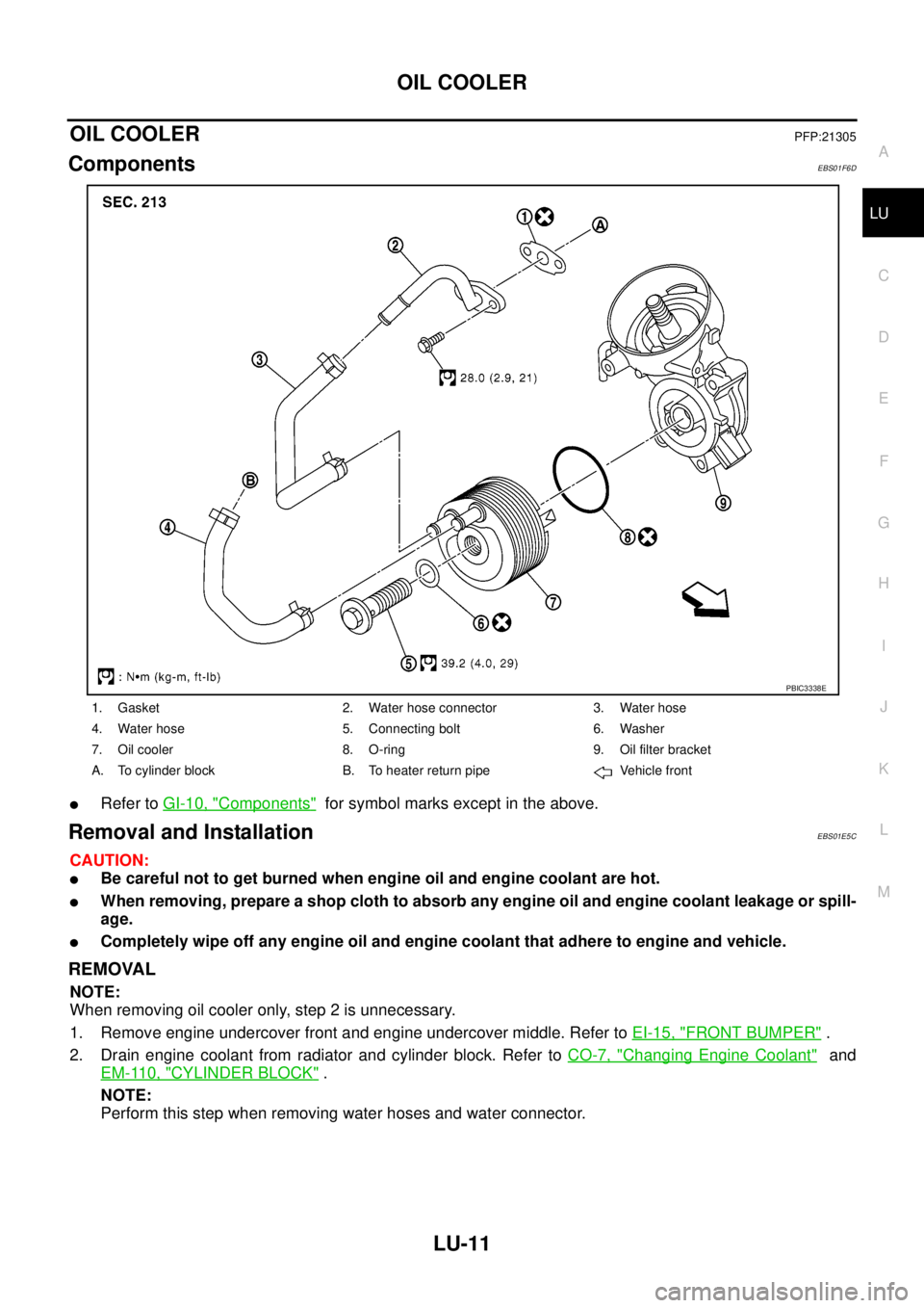
OIL COOLERPFP:21305
ComponentsEBS01F6D
lRefer toGI-10, "Components"for symbol marks except in the above.
Removal and InstallationEBS01E5C
CAUTION:
lBe careful not to get burned when engine oil and engine coolant are hot.
lWhen removing, prepare a shop cloth to absorb any engine oil and engine coolant leakage or spill-
age.
lCompletely wipe off any engine oil and engine coolant that adhere to engine and vehicle.
REMOVAL
NOTE:
When removing oil cooler only, step 2 is unnecessary.
1. Remove engine undercover front and engine undercover middle. Refer toEI-15, "
FRONT BUMPER".
2. Drain engine coolant from radiator and cylinder block. Refer toCO-7, "
Changing Engine Coolant"and
EM-110, "
CYLINDER BLOCK".
NOTE:
Perform this step when removing water hoses and water connector.
1. Gasket 2. Water hose connector 3. Water hose
4. Water hose 5. Connecting bolt 6. Washer
7. Oil cooler 8. O-ring 9. Oil filter bracket
A. To cylinder block B. To heater return pipe Vehicle front
PBIC3338E
Page 2294 of 3171

ENGINE MAINTENANCE
MA-19
C
D
E
F
G
H
I
J
K
MA
B
MA
A/C COMPRESSOR, ALTERNATOR AND WATER PUMP BELT
1. Loosen idler pulley lock nut (D).
2. Turn adjusting nut (C) to adjust. Refer toMA-18, "
Deflection Adjustment".
3. Tighten lock nut (D).
Changing Engine CoolantELS001JQ
WARNING:
lTo avoid being scalded, do not change engine coolant when engine is hot.
lWrap a thick cloth around cap and carefully remove radiator cap. First, turn radiator cap a quarter
of a turn to release built-up pressure. Then turn the cap all the way.
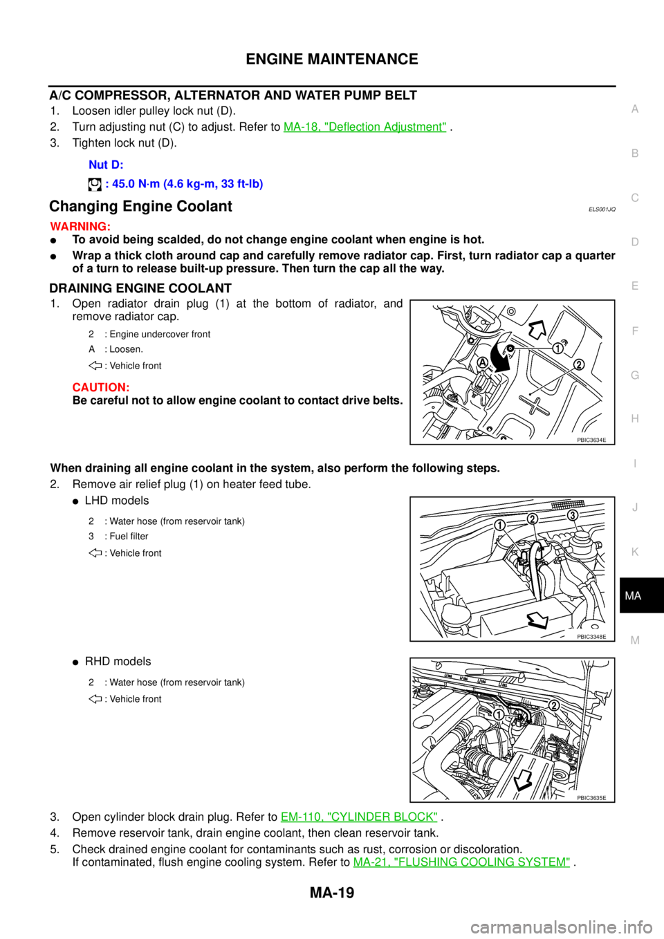
DRAINING ENGINE COOLANT
1. Open radiator drain plug (1) at the bottom of radiator, and
remove radiator cap.
CAUTION:
Be careful not to allow engine coolant to contact drive belts.
When draining all engine coolant in the system, also perform the following steps.
2. Remove air relief plug (1) on heater feed tube.
lLHD models
lRHD models
3. Open cylinder block drain plug. Refer toEM-110, "
CYLINDER BLOCK".
4. Remove reservoir tank, drain engine coolant, then clean reservoir tank.
5. Check drained engine coolant for contaminants such as rust, corrosion or discoloration.
If contaminated, flush engine cooling system. Refer toMA-21, "
FLUSHING COOLING SYSTEM". Nut D:
: 45.0 N·m (4.6 kg-m, 33 ft-lb)
2 : Engine undercover front
A : Loosen.
: Vehicle front
PBIC3634E
2 : Water hose (from reservoir tank)
3:Fuelfilter
: Vehicle front
PBIC3348E
2 : Water hose (from reservoir tank)
: Vehicle front
PBIC3635E
Page 2295 of 3171

MA-20
ENGINE MAINTENANCE
REFILLING ENGINE COOLANT
1. Install reservoir tank, and radiator drain plug.
CAUTION:
Be sure to clean radiator drain plug and install with new O-ring.
lIf water drain plug on cylinder block is removed, close and tighten it. Refer toEM-110, "CYLIN-
DER BLOCK".
2. Make sure that each hose clamp has been firmly tightened.
3. Fill radiator and reservoir tank to the specified level.
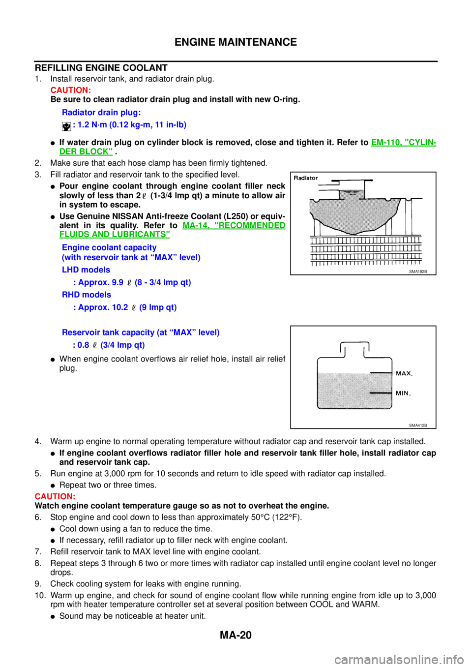
lPour engine coolant through engine coolant filler neck
slowly of less than 2 (1-3/4 lmp qt) a minute to allow air
in system to escape.
lUse Genuine NISSAN Anti-freeze Coolant (L250) or equiv-
alent in its quality. Refer toMA-14, "
RECOMMENDED
FLUIDS AND LUBRICANTS"
lWhen engine coolant overflows air relief hole, install air relief
plug.
4. Warm up engine to normal operating temperature without radiator cap and reservoir tank cap installed.
lIf engine coolant overflows radiator filler hole and reservoir tank filler hole, install radiator cap
and reservoir tank cap.
5. Run engine at 3,000 rpm for 10 seconds and return to idle speed with radiator cap installed.
lRepeat two or three times.
CAUTION:
Watch engine coolant temperature gauge so as not to overheat the engine.
6. Stop engine and cool down to less than approximately 50°C(122°F).
lCool down using a fan to reduce the time.
lIf necessary, refill radiator up to filler neck with engine coolant.
7. Refill reservoir tank to MAX level line with engine coolant.
8. Repeat steps 3 through 6 two or more times with radiator cap installed until engine coolant level no longer
drops.
9. Check cooling system for leaks with engine running.
10. Warm up engine, and check for sound of engine coolant flow while running engine from idle up to 3,000
rpm with heater temperature controller set at several position between COOL and WARM.
lSound may be noticeable at heater unit.Radiator drain plug:
: 1.2 N·m (0.12 kg-m, 11 in-lb)
Engine coolant capacity
(with reservoir tank at “MAX” level)
LHD models
: Approx. 9.9 (8 - 3/4 lmp qt)
RHD models
: Approx. 10.2 (9 lmp qt)
SMA182B
Reservoir tank capacity (at “MAX” level)
: 0.8 (3/4 lmp qt)
SMA412B
Page 2389 of 3171

MTC-2
Schematic —LHD MODELS— ............................... 38
Wiring Diagram —A/C— —LHD MODELS— ......... 39
Schematic —RHD MODELS— ............................... 44
Wiring Diagram —A/C— —RHD MODELS— ......... 45
Front Air Control Terminals and Reference Value... 49
PIN CONNECTOR TERMINAL LAYOUT ............ 49
TERMINALS AND REFERENCE VALUE FOR
FRONT AIR CONTROL ....................................... 49
A/C System Self-diagnosis Function ...................... 51
DESCRIPTION .................................................... 51
Operational Check .................................................. 53
CHECKING BLOWER ......................................... 53
CHECKING DISCHARGE AIR ............................ 53
CHECKING RECIRCULATION ............................ 53
CHECKING TEMPERATURE DECREASE ......... 54
CHECKING TEMPERATURE INCREASE .......... 54
CHECK A/C SWITCH .......................................... 54
Power Supply and Ground Circuit for Front Air Con-
trol ........................................................................... 55
INSPECTION FLOW ........................................... 55
COMPONENT DESCRIPTION ............................ 56
DIAGNOSTIC PROCEDURE FOR A/C SYSTEM... 56
Mode Door Motor Circuit ........................................ 58
INSPECTION FLOW ........................................... 58
SYSTEM DESCRIPTION .................................... 59
COMPONENT DESCRIPTION ............................ 59
DIAGNOSTIC PROCEDURE FOR MODE
DOOR MOTOR ................................................... 59
Air Mix Door Motor Circuit ...................................... 63
INSPECTION FLOW ........................................... 63
SYSTEM DESCRIPTION .................................... 64
COMPONENT DESCRIPTION ............................ 64
DIAGNOSTIC PROCEDURE FOR AIR MIX
DOOR MOTOR (FRONT) .................................... 64
Intake Door Motor Circuit ........................................ 68
INSPECTION FLOW ........................................... 68
SYSTEM DESCRIPTION .................................... 69
COMPONENT DESCRIPTION ............................ 69
DIAGNOSTIC PROCEDURE FOR INTAKE
DOOR MOTOR ................................................... 69
Blower Motor Circuit ............................................... 71
INSPECTION FLOW ........................................... 71
SYSTEM DESCRIPTION .................................... 72
COMPONENT DESCRIPTION ............................ 72
DIAGNOSTIC PROCEDURE FOR BLOWER
MOTOR ............................................................... 73
COMPONENT INSPECTION .............................. 77
Magnet Clutch Circuit ............................................. 79
INSPECTION FLOW ........................................... 79
SYSTEM DESCRIPTION .................................... 80
DIAGNOSTIC PROCEDURE FOR MAGNET
CLUTCH .............................................................. 80
COMPONENT INSPECTION .............................. 85
Insufficient Cooling ................................................. 86
INSPECTION FLOW ........................................... 86
PERFORMANCE TEST DIAGNOSES ................ 87
PERFORMANCE CHART ................................... 89
TROUBLE DIAGNOSES FOR UNUSUAL PRES-
SURE ................................................................... 90Insufficient Heating ................................................. 93
INSPECTION FLOW ............................................ 93
Noise ....................................................................... 94
INSPECTION FLOW ............................................ 94
Self-diagnosis ......................................................... 95
INSPECTION FLOW ............................................ 95
Intake Sensor Circuit ............................................... 95
COMPONENT DESCRIPTION ............................ 95
DIAGNOSTIC PROCEDURE FOR INTAKE SEN-
SOR ..................................................................... 96
COMPONENT INSPECTION ............................... 97
CONTROL UNIT ........................................................ 98
Removal and Installation ......................................... 98
REMOVAL ............................................................ 98
INSTALLATION .................................................... 98
INTAKE SENSOR ...................................................... 99
Removal and Installation ......................................... 99
REMOVAL ............................................................ 99
INSTALLATION .................................................... 99
BLOWER MOTOR ...................................................100
Components ..........................................................100
Removal and Installation .......................................100
REMOVAL ..........................................................100
INSTALLATION ..................................................100
AIR CONDITIONER FILTER ...................................101
Removal and Installation .......................................101
FUNCTION ........................................................101
REPLACEMENT TIMING ..................................101
REPLACEMENT PROCEDURE ........................101
HEATER & COOLING UNIT ASSEMBLY ...............103
Components ..........................................................103
Removal and Installation .......................................105
REMOVAL ..........................................................105
INSTALLATION ..................................................105
HEATER CORE .......................................................106
Components ..........................................................106
Removal and Installation .......................................107
REMOVAL ..........................................................107
INSTALLATION ..................................................107
DEFROSTER DOOR MOTOR .................................108
Components ..........................................................108
Removal and Installation .......................................108
REMOVAL ..........................................................108
INSTALLATION ..................................................108
INTAKE DOOR MOTOR ..........................................109
Components ..........................................................109
Removal and Installation .......................................109
REMOVAL ..........................................................109
INSTALLATION ..................................................109
MODE DOOR MOTOR ............................................110
Components ..........................................................110
Removal and Installation .......................................110
REMOVAL ..........................................................110
INSTALLATION ..................................................110
AIR MIX DOOR MOTOR ......................................... 111
Components .......................................................... 111
Removal and Installation ....................................... 111
REMOVAL .......................................................... 111
INSTALLATION .................................................. 111
Page 2410 of 3171

REFRIGERATION SYSTEM
MTC-23
C
D
E
F
G
H
I
K
L
MA
B
MTC
1. Defroster nozzle 2. LH side demister duct 3. LH ventilator duct
4. RH side demister duct 5. RH ventilator duct 6. Center ventilator duct
7. Heater and cooling unit assembly 8. Floor duct 9. Clips
10. Heat duct
Page 2437 of 3171

MTC-50
TROUBLE DIAGNOSIS
21 V Mode door motor feedback ON — 0 - 5V
22 SB Air mix door motor feedback ON — 0 - 5V
23 G Sensor power ON — 5V
25 LG Rear defroster status
26 P Sensor return ON — 0 - 5V
36 PPTC heater relay 1
(LHD models)ONRelay ON Battery voltage
Relay OFF 0V
37 LGPTC heater relay 2
(LHD models)ONRelay ON Battery voltage
Relay OFF 0V
38 BRPTC heater relay 3
(LHD models)ONRelay ON Battery voltage
Relay OFF 0V
39 YSeat heater
(LHD models)ONSeat heater ON Battery voltage
Seat heater OFF 0V
40 RMirror heater
(LHD models)ONMirror heater ON Battery voltage
Mirror heater OFF 0V
41 LCAN-H
(LHD models)ON — 0 - 5V
42 PCAN-L
(LHD models)ON — 0 - 5V Te r m i -
nal No.Wire
colorItemIgnition
switchConditionVoltage (V)
(Approx.)