Page 2499 of 3171
MTC-112
BLOWER MOTOR RESISTOR
BLOWER MOTOR RESISTOR
PFP:27077
ComponentsEJS005H6
Blower Motor Resistor - Heater and Cooling Unit Assembly
Removal and InstallationEJS006DB
REMOVAL
1. Remove the steering member.
2. Remove the heater and cooling unit assembly. Refer toMTC-103, "
HEATER&COOLING UNIT ASSEM-
BLY".
3. Disconnect the blower motor resistor electrical connector.
4. Remove the two screws and remove the blower motor resistor.
INSTALLATION
Installation is in the reverse order of removal.
MJIB0249E
1. Heater and cooling unit assembly 2. Intake door motor 3. Air mix door motor
4. Blower motor resistor 5. Mode door motor 6. Defroster door motor
Page 2500 of 3171
DUCTS AND GRILLES
MTC-113
C
D
E
F
G
H
I
K
L
MA
B
MTC
DUCTS AND GRILLESPFP:27860
ComponentsEJS005H8
Ducts - Heater and Cooling Unit Assembly
MJIB0250E
Page 2501 of 3171
MTC-114
DUCTS AND GRILLES
1. Defroster nozzle 2. LH side demister duct 3. LH ventilator duct
4. RH side demister duct 5. RH ventilator duct 6. Center ventilator duct
7. Heater and cooling unit assembly 8. Floor duct 9. Clips
10. Heat duct
Page 2516 of 3171
REFRIGERANT LINES
MTC-129
C
D
E
F
G
H
I
K
L
MA
B
MTC
Removal and Installation for EvaporatorEJS005HK
Heater and Cooling Unit Assembly
MJIB0252E
1. Heater core cover 2. Heater core pipe bracket 3. Heater core
4. Upper bracket 5. Upper heater and cooling unit case 6. A/C evaporator
7. Lower heater and cooling unit case 8. Blower motor 9. Blower motor resistor
Page 2517 of 3171

MTC-130
REFRIGERANT LINES
REMOVAL
1. Remove the heater core. Refer toMTC-106, "HEATER CORE".
2. Remove the defroster mode door arm.
3. Separate the heater core and cooling unit case.
4. Remove the evaporator.
INSTALLATION
Installation is in the reverse order of removal.
CAUTION:
Replace the O-rings on the low-pressure flexible hose and the high-pressure pipe with new ones.
Apply compressor oil to the O-rings before installing them.
Removal and Installation for Expansion ValveEJS005HM
REMOVAL
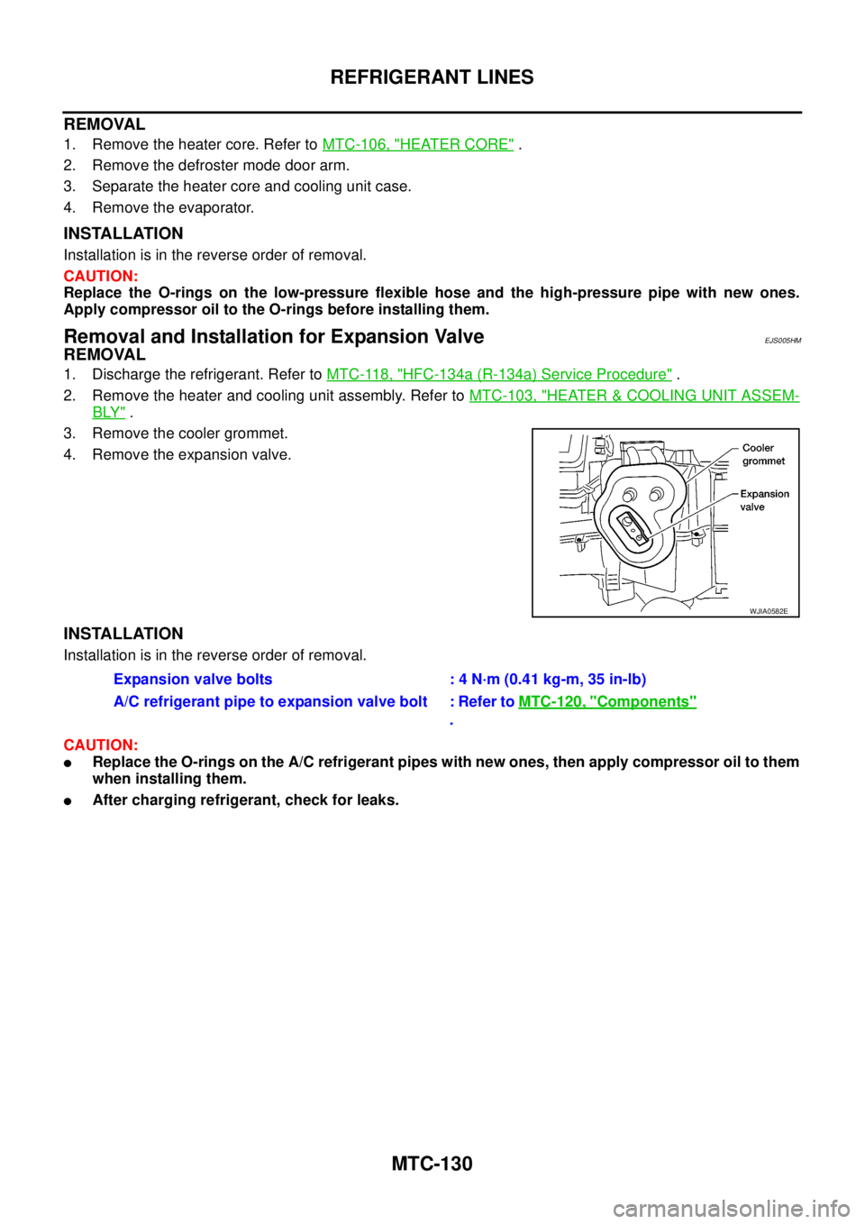
1. Discharge the refrigerant. Refer toMTC-118, "HFC-134a (R-134a) Service Procedure".
2. Remove the heater and cooling unit assembly. Refer toMTC-103, "
HEATER&COOLING UNIT ASSEM-
BLY".
3. Remove the cooler grommet.
4. Remove the expansion valve.
INSTALLATION
Installation is in the reverse order of removal.
CAUTION:
lReplace the O-rings on the A/C refrigerant pipes with new ones, then apply compressor oil to them
when installing them.
lAfter charging refrigerant, check for leaks.
WJIA0582E
Expansion valve bolts : 4 N·m (0.41 kg-m, 35 in-lb)
A/C refrigerant pipe to expansion valve bolt : Refer toMTC-120, "
Components"
.
Page 2520 of 3171

REFRIGERANT LINES
MTC-133
C
D
E
F
G
H
I
K
L
MA
B
MTC
CHECKING PROCEDURE
To prevent inaccurate or false readings, make sure there is no refrigerant vapor, shop chemicals, or cigarette
smoke in the vicinity of the vehicle. Perform the leak test in calm area (low air/wind movement) so that the
leaking refrigerant is not dispersed.
1. Turn engine OFF.
2. Connect a suitable A/C manifold gauge set (SST) to the A/C service valves.
3. Check if the A/C refrigerant pressure is at least 345 kPa (3.45 bar, 3.52 kg/cm
2, 50 psi) above 16°C. If
less than specification, recover/evacuate and recharge the system with the specified amount of refriger-
ant.
NOTE:
At temperatures below 16°C, leaks may not be detected since the system may not reach 345 kPa (3.45
bar, 3.52 kg/cm
2,50psi).
4. Perform the leak test from the high-pressure side (compressor discharge a to evaporator inlet g) to the
low-pressure side (evaporator drain hose h to shaft seal l). Refer toMTC-120, "
Components". Perform a
leak check for the following areas carefully. Clean the component to be checked and move the leak
detected probe completely around the connection/component.
Compressor
Check the fitting of high- and low-pressure flexible hoses, relief valve and shaft seal.
Liquid tank
Check the refrigerant pressure sensor.
Service valves
Check all around the service valves. Ensure service valve caps are secured on the service valves (to pre-
vent leaks).
NOTE:
After removing A/C manifold gauge set from service valves, wipe any residue from valves to prevent any
false readings by leak detector.
Cooling unit (Evaporator)
With engine OFF, turn blower fan on “High” for at least 15 seconds to dissipate any refrigerant trace in the
cooling unit. Wait a minimum of 10 minutes accumulation time (refer to the manufacturer’s recommended
procedure for actual wait time) before inserting the leak detector probe into the drain hose.
Keep the probe inserted for at least 10 seconds. Use caution not to contaminate the probe tip with water
or dirt that may be in the drain hose.
5. If a leak detector detects a leak, verify at least once by blowing compressed air into area of suspected
leak, then repeat check as outlined above.
6. Do not stop when one leak is found. Continue to check for additional leaks at all system components.
If no leaks are found, perform steps 7 - 10.
7. Start engine.
8. Set the heater A/C control as follows;
a. A/C switch: ON
b. MODE control dial: VENT (Ventilation)
c. Intake door position: Recirculation
d. Max. cold temperature
e. Fan speed: High
9. Run engine at 1,500 rpm for at least 2 minutes.
10. Turn engine off and perform leak check again following steps 4 through 6 above.
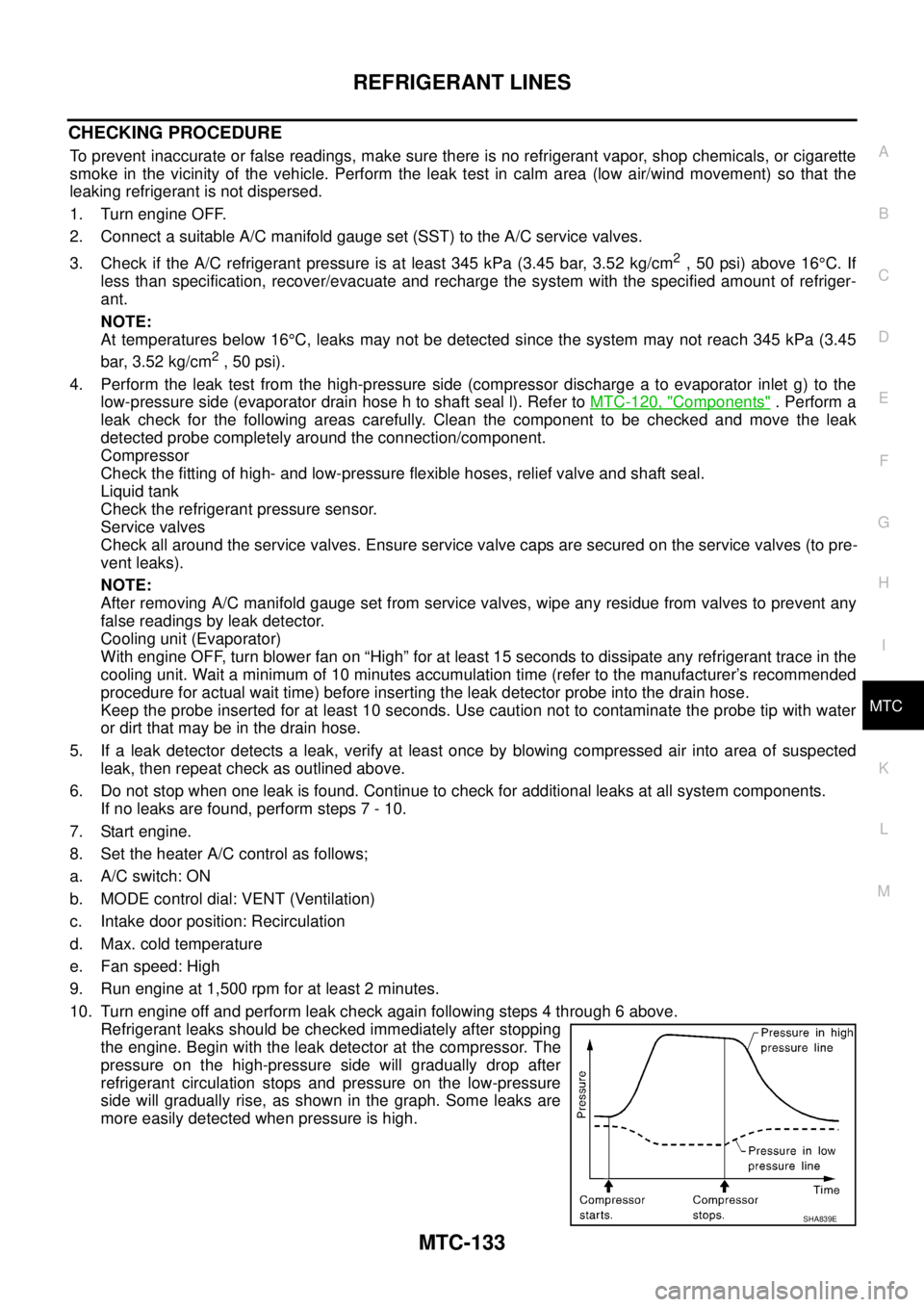
Refrigerant leaks should be checked immediately after stopping
the engine. Begin with the leak detector at the compressor. The
pressure on the high-pressure side will gradually drop after
refrigerant circulation stops and pressure on the low-pressure
side will gradually rise, as shown in the graph. Some leaks are
more easily detected when pressure is high.
SHA839E
Page 2892 of 3171
FRONT SEAT
SE-21
C
D
E
F
G
H
J
K
L
MA
B
SE
1. Headrest 2. Headrest holder (free) 3. Headrest holder (locked)
4. Seatback board 5. Seatback assembly 6. Lumbar support lever knob
7. Seat cushion trim 8. Seat cushion heater unit 9. Seat cushion pad
10. Seat cushion frame 11. Power seat switch 12. Power seat switch escutcheon
13. Reclining switch knob 14. Slide & lifter switch knob 15. Seat cushion inner finisher
16. Seat adjuster assembly 17. Front leg cover 18. Seat cushion front finisher
19. Seat control unit 20. Power seat harness 21. Seat slide cover
22. Seat cushion outer finisher 23. Gasket 24. Rear leg cover
25. Panel 26. Seat belt buckle 27. Lifter dial
28. Reclining lever knob
Page 2894 of 3171

FRONT SEAT
SE-23
C
D
E
F
G
H
J
K
L
MA
B
SE
Removal and InstallationEIS00C62
REMOVAL
When removing or installing the seat trim, handle it carefully to keep dirt out and avoid damage.
CAUTION:
lBefore removing the front seat, turn the ignition switch off, disconnect both battery cables and
wait at least 3 minutes.
lWhen checking the power seat circuit for continuity using a circuit tester, do not confuse its con-
nector with the side air bag module connector. Such an error may cause the air bag to deploy.
lDo not drop, tilt, or bump the side air bag module while installing the seat. Always handle it with
care.
lAfter front side air bag module inflates, front seatback assembly must be replaced.
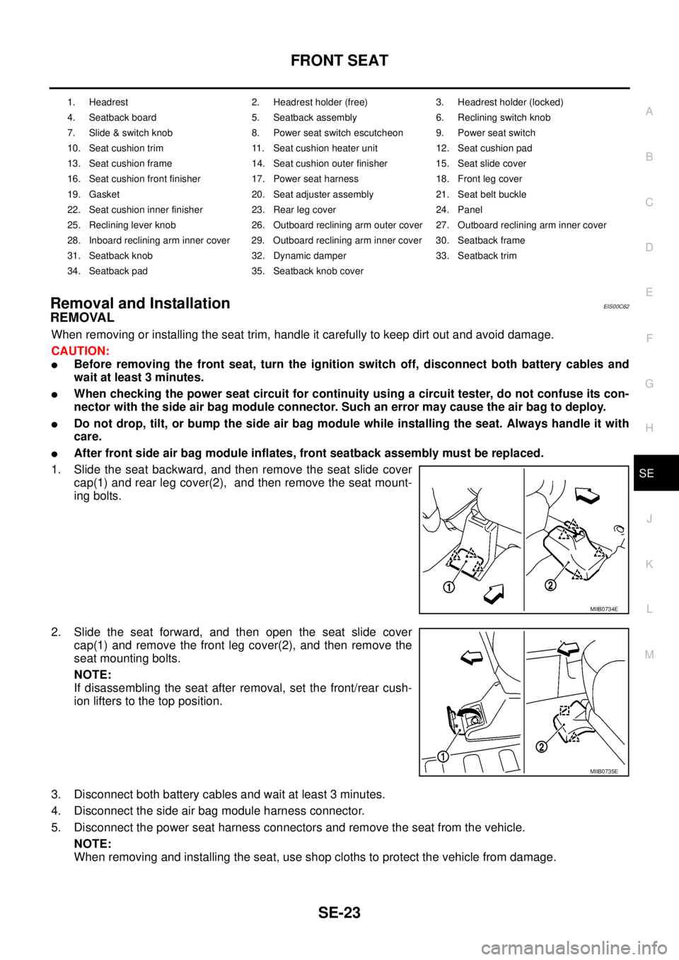
1. Slide the seat backward, and then remove the seat slide cover
cap(1) and rear leg cover(2), and then remove the seat mount-
ing bolts.
2. Slide the seat forward, and then open the seat slide cover
cap(1) and remove the front leg cover(2), and then remove the
seat mounting bolts.
NOTE:
If disassembling the seat after removal, set the front/rear cush-
ion lifters to the top position.
3. Disconnect both battery cables and wait at least 3 minutes.
4. Disconnect the side air bag module harness connector.
5. Disconnect the power seat harness connectors and remove the seat from the vehicle.
NOTE:
When removing and installing the seat, use shop cloths to protect the vehicle from damage.
1. Headrest 2. Headrest holder (free) 3. Headrest holder (locked)
4. Seatback board 5. Seatback assembly 6. Reclining switch knob
7. Slide & switch knob 8. Power seat switch escutcheon 9. Power seat switch
10. Seat cushion trim 11. Seat cushion heater unit 12. Seat cushion pad
13. Seat cushion frame 14. Seat cushion outer finisher 15. Seat slide cover
16. Seat cushion front finisher 17. Power seat harness 18. Front leg cover
19. Gasket 20. Seat adjuster assembly 21. Seat belt buckle
22. Seat cushion inner finisher 23. Rear leg cover 24. Panel
25. Reclining lever knob 26. Outboard reclining arm outer cover 27. Outboard reclining arm inner cover
28. Inboard reclining arm inner cover 29. Outboard reclining arm inner cover 30. Seatback frame
31. Seatback knob 32. Dynamic damper 33. Seatback trim
34. Seatback pad 35. Seatback knob cover
MIIB0734E
MIIB0735E