2005 NISSAN NAVARA heater
[x] Cancel search: heaterPage 337 of 3171

ATC-3
C
D
E
F
G
H
I
K
L
MA
B
AT C BLOWER MOTOR .................................................. 121
Components ......................................................... 121
Removal and Installation ...................................... 121
REMOVAL ......................................................... 121
INSTALLATION ................................................. 121
AIR CONDITIONER FILTER ................................... 122
Removal and Installation ...................................... 122
FUNCTION ........................................................ 122
REPLACEMENT TIMING .................................. 122
REPLACEMENT PROCEDURE ....................... 122
HEATER & COOLING UNIT ASSEMBLY .............. 124
Components ......................................................... 124
Removal and Installation ...................................... 126
REMOVAL ......................................................... 126
INSTALLATION ................................................. 126
HEATER CORE ...................................................... 127
Components ......................................................... 127
Removal and Installation ...................................... 127
REMOVAL ......................................................... 127
INSTALLATION ................................................. 127
HEATER PUMP ...................................................... 128
Components ......................................................... 128
Removal and Installation ...................................... 128
REMOVAL ......................................................... 128
INSTALLATION ................................................. 128
INTAKE DOOR MOTOR ......................................... 129
Components ......................................................... 129
Removal and Installation ...................................... 129
REMOVAL ......................................................... 129
INSTALLATION ................................................. 129
MODE DOOR MOTOR ........................................... 130
Components ......................................................... 130
Removal and Installation ...................................... 130
REMOVAL ......................................................... 130
INSTALLATION ................................................. 130
AIR MIX DOOR MOTOR ......................................... 131
Components ......................................................... 131
Removal and Installation ...................................... 131
AIR MIX DOOR MOTOR (DRIVER) .................. 131
AIR MIX DOOR MOTOR (PASSENGER) ......... 131
VARIABLE BLOWER CONTROL .......................... 133
Components ......................................................... 133
Removal and Installation ...................................... 133
REMOVAL ......................................................... 133
INSTALLATION ................................................. 133
DUCTS AND GRILLES .......................................... 134
Components ......................................................... 134
Removal and Installation ...................................... 136
CONSOLE DUCTS AND CONSOLE GRILLE .. 136
DEFROSTER NOZZLE ..................................... 136
RH AND LH SIDE DEMISTER DUCT ............... 136
RH AND LH VENTILATOR DUCT ..................... 136
CENTER VENTILATOR DUCT ......................... 136
FLOOR CONNECTOR DUCT ........................... 136
FRONT AND REAR FLOOR DUCTS ............... 137
REAR OVERHEAD DUCTS .............................. 137
SIDE REAR FLOOR DUCT .............................. 137
GRILLES ........................................................... 137REFRIGERANT LINES ...........................................138
HFC-134a (R-134a) Service Procedure ...............138
SETTING OF SERVICE TOOLS AND EQUIP-
MENT ................................................................138
Components .........................................................140
Removal and Installation for Compressor ............142
REMOVAL .........................................................142
INSTALLATION .................................................142
Removal and Installation for Compressor Clutch . 143
REMOVAL .........................................................143
INSPECTION ....................................................144
INSTALLATION .................................................144
BREAK-IN OPERATION ....................................146
Removal and Installation for High-pressure Flexible
A/C Hose ..............................................................146
REMOVAL .........................................................146
INSTALLATION .................................................146
Removal and Installation for High-pressure A/C
Pipe ......................................................................146
REMOVAL .........................................................146
INSTALLATION .................................................146
Removal and Installation for Low-pressure Flexible
A/C Hose ..............................................................146
REMOVAL .........................................................146
INSTALLATION .................................................146
Removal and Installation for Low-pressure A/C Pipe.147
REMOVAL .........................................................147
INSTALLATION .................................................147
Removal and Installation for Refrigerant Pressure
Sensor ..................................................................147
REMOVAL .........................................................147
INSTALLATION .................................................147
Removal and Installation for Condenser ..............147
REMOVAL .........................................................147
INSTALLATION .................................................148
Removal and Installation for Evaporator ..............149
REMOVAL .........................................................149
INSTALLATION .................................................149
Removal and Installation for Expansion Valve ......150
REMOVAL .........................................................150
INSTALLATION .................................................150
Checking for Refrigerant Leaks ............................150
Checking System for Leaks Using the Fluorescent
Leak Detector .......................................................150
Dye Injection .........................................................151
Electronic Refrigerant Leak Detector ....................151
PRECAUTIONS FOR HANDLING LEAK
DETECTOR .......................................................151
CHECKING PROCEDURE ...............................152
SERVICE DATA AND SPECIFICATIONS (SDS) ....154
Service Data and Specifications (SDS) ................154
COMPRESSOR ................................................154
LUBRICANT ......................................................154
REFRIGERANT .................................................154
ENGINE IDLING SPEED ..................................154
BELT TENSION .................................................154
Page 357 of 3171

REFRIGERATION SYSTEM
ATC-23
C
D
E
F
G
H
I
K
L
MA
B
AT C
1. Defroster nozzle 2. LH side demister duct 3. LH ventilator duct
4. RH side demister duct 5. RH ventilator duct 6. Center ventilation duct
7. Heater and cooling unit assembly 8. Floor connector duct grilles 9. Floor connector duct
10. Front floor duct 11. Rear floor duct
Page 387 of 3171
TROUBLE DIAGNOSIS
ATC-53
C
D
E
F
G
H
I
K
L
MA
B
AT C
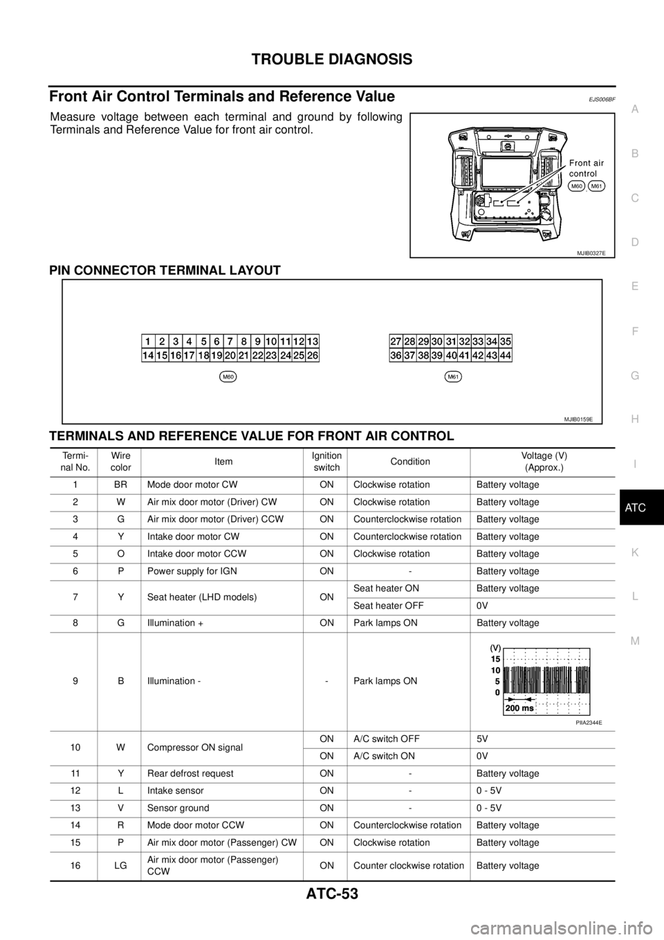
Front Air Control Terminals and Reference ValueEJS006BF
Measure voltage between each terminal and ground by following
Terminals and Reference Value for front air control.
PIN CONNECTOR TERMINAL LAYOUT
TERMINALS AND REFERENCE VALUE FOR FRONT AIR CONTROL
MJIB0327E
MJIB0159E
Te r m i -
nal No.Wire
colorItemIgnition
switchConditionVo l ta g e (V )
(Approx.)
1 BR Mode door motor CW ON Clockwise rotation Battery voltage
2 W Air mix door motor (Driver) CW ON Clockwise rotation Battery voltage
3 G Air mix door motor (Driver) CCW ON Counterclockwise rotation Battery voltage
4 Y Intake door motor CW ON Counterclockwise rotation Battery voltage
5 O Intake door motor CCW ON Clockwise rotation Battery voltage
6 P Power supply for IGN ON - Battery voltage
7 Y Seat heater (LHD models) ONSeat heater ON Battery voltage
Seat heater OFF 0V
8 G Illumination + ON Park lamps ON Battery voltage
9 B Illumination - - Park lamps ON
10 W Compressor ON signalON A/C switch OFF 5V
ON A/C switch ON 0V
11 Y Rear defrost request ON - Battery voltage
12 L Intake sensor ON - 0 - 5V
13 V Sensor ground ON - 0 - 5V
14 R Mode door motor CCW ON Counterclockwise rotation Battery voltage
15 P Air mix door motor (Passenger) CW ON Clockwise rotation Battery voltage
16 LGAir mix door motor (Passenger)
CCWON Counter clockwise rotation Battery voltage
PIIA2344E
Page 388 of 3171

ATC-54
TROUBLE DIAGNOSIS
19 GR Power supply for BAT - - Battery voltage
20 B Ground - - 0V
21 V Mode door motor feedback ON - 0 - 5V
22 SB Air mix door motor (Driver) feedback ON - 0 - 5V
23 G Sensor power ON - 5V
26 P Sensor return ON - 0V
27 R In-vehicle sensor signal ON - 0 - 5V
28 W Ambient sensor ON - 0 - 5V
29 G Optical sensor (Driver) ON - 0 - 5V
31 PPTC heater relay 1
(LHD models)ONRelay ON Battery voltage
Relay OFF 0V
32 V Variable blower control ON - 0 - 5V
33 BR In-vehicle sensor motor (+) ON - Battery voltage
34 O In-vehicle sensor motor (-) ON - 0V
35 LG Fan ON signalON Blower switch OFF 5V
ON Blower switch ON 0V
36 SBAir mix door motor (Passenger)
feedbackON - 0 - 5V
37 GR Optical sensor (Passenger) ON - 0 - 5V
38 B Blower request ONBlower motor OFF Battery voltage
Blower motor ON 0V
40 LGPTC heater relay 2
(LHD models)ONRelay ON Battery voltage
Relay OFF 0V
41 L CAN-H ON - 0 - 5V
42 P CAN-L ON - 0 - 5V
43 BRPTC heater relay 3
(LHD models)ONRelay ON Battery voltage
Relay OFF 0V
44 R Mirror heater (LHD models) ONHeater OFF 0V
Heater ON Battery voltage Te r m i -
nal No.Wire
colorItemIgnition
switchConditionVoltage (V)
(Approx.)
Page 399 of 3171
TROUBLE DIAGNOSIS
ATC-65
C
D
E
F
G
H
I
K
L
MA
B
AT C
COMPONENT DESCRIPTION
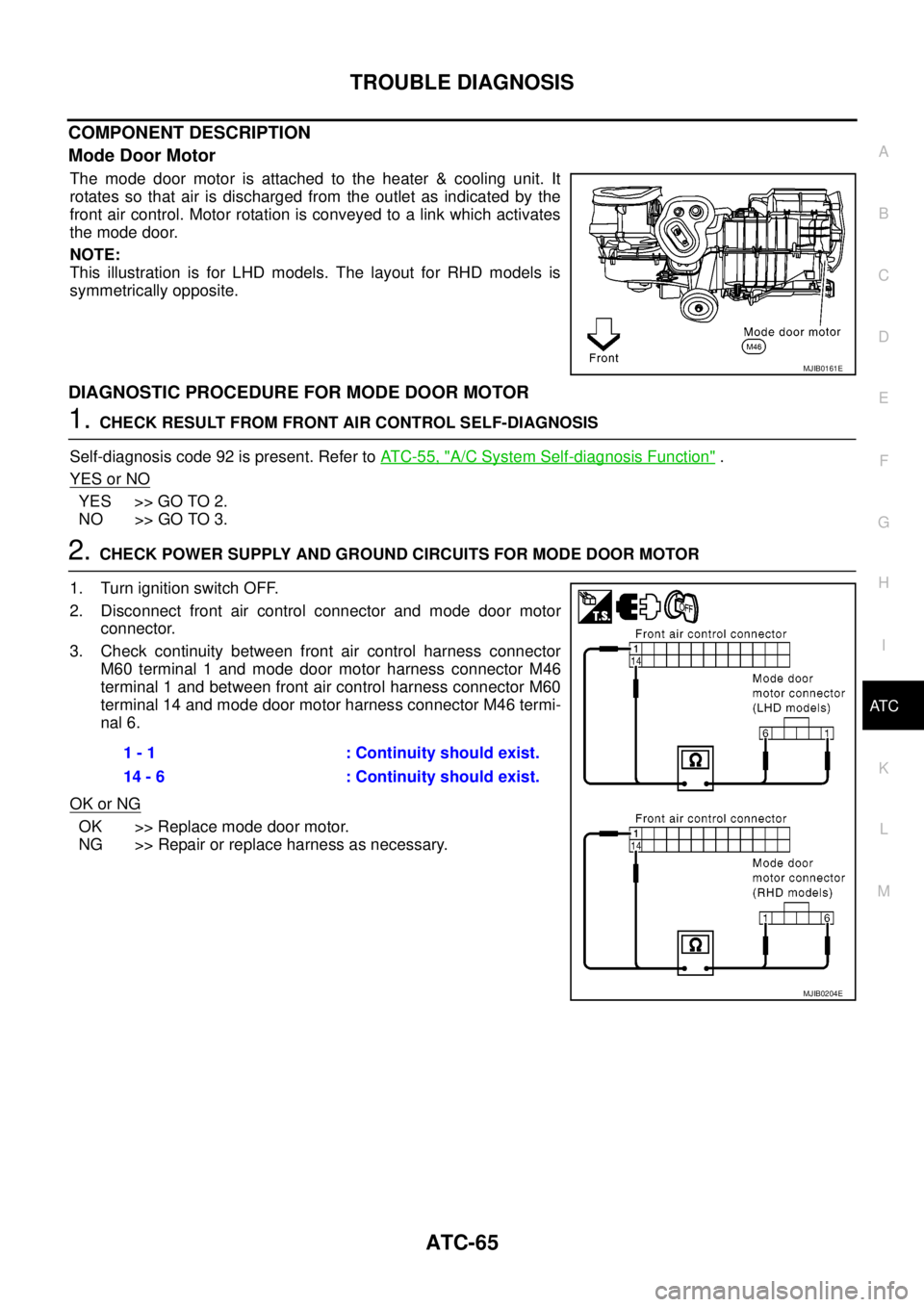
Mode Door Motor
The mode door motor is attached to the heater & cooling unit. It
rotates so that air is discharged from the outlet as indicated by the
front air control. Motor rotation is conveyed to a link which activates
themodedoor.
NOTE:
This illustration is for LHD models. The layout for RHD models is
symmetrically opposite.
DIAGNOSTIC PROCEDURE FOR MODE DOOR MOTOR
1.CHECK RESULT FROM FRONT AIR CONTROL SELF-DIAGNOSIS
Self-diagnosis code 92 is present. Refer toAT C - 5 5 , "
A/C System Self-diagnosis Function".
YES or NO
YES >> GO TO 2.
NO >> GO TO 3.
2.CHECK POWER SUPPLY AND GROUND CIRCUITS FOR MODE DOOR MOTOR
1. Turn ignition switch OFF.
2. Disconnect front air control connector and mode door motor
connector.
3. Check continuity between front air control harness connector
M60 terminal 1 and mode door motor harness connector M46
terminal 1 and between front air control harness connector M60
terminal 14 and mode door motor harness connector M46 termi-
nal 6.
OK or NG
OK >> Replace mode door motor.
NG >> Repair or replace harness as necessary.
MJIB0161E
1 - 1 : Continuity should exist.
14 - 6 : Continuity should exist.
MJIB0204E
Page 404 of 3171
ATC-70
TROUBLE DIAGNOSIS
COMPONENT DESCRIPTION
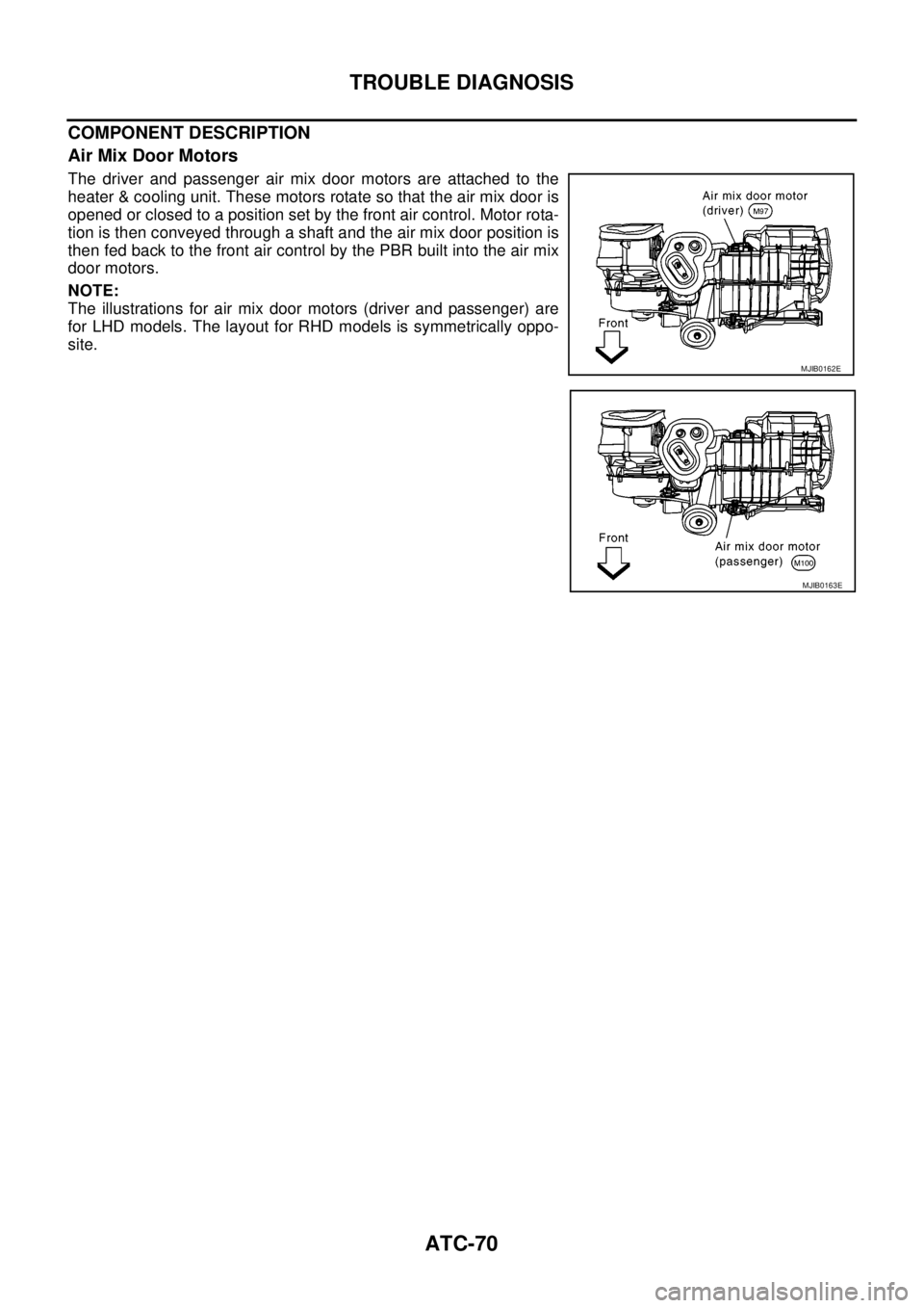
Air Mix Door Motors
The driver and passenger air mix door motors are attached to the
heater & cooling unit. These motors rotate so that the air mix door is
opened or closed to a position set by the front air control. Motor rota-
tion is then conveyed through a shaft and the air mix door position is
then fed back to the front air control by the PBR built into the air mix
door motors.
NOTE:
The illustrations for air mix door motors (driver and passenger) are
for LHD models. The layout for RHD models is symmetrically oppo-
site.
MJIB0162E
MJIB0163E
Page 448 of 3171
ATC-114
TROUBLE DIAGNOSIS
Intake Sensor Circuit
EJS006BZ
COMPONENT DESCRIPTION
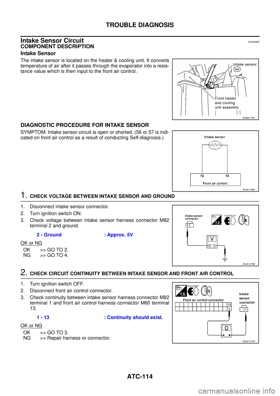
Intake Sensor
The intake sensor is located on the heater & cooling unit. It converts
temperature of air after it passes through the evaporator into a resis-
tance value which is then input to the front air control.
DIAGNOSTIC PROCEDURE FOR INTAKE SENSOR
SYMPTOM: Intake sensor circuit is open or shorted. (56 or 57 is indi-
cated on front air control as a result of conducting Self-diagnosis.)
1.CHECK VOLTAGE BETWEEN INTAKE SENSOR AND GROUND
1. Disconnect intake sensor connector.
2. Turn ignition switch ON.
3. Check voltage between intake sensor harness connector M82
terminal 2 and ground.
OK or NG
OK >> GO TO 2.
NG >> GO TO 4.
2.CHECK CIRCUIT CONTINUITY BETWEEN INTAKE SENSOR AND FRONT AIR CONTROL
1. Turn ignition switch OFF.
2. Disconnect front air control connector.
3. Check continuity between intake sensor harness connector M82
terminal 1 and front air control harness connector M60 terminal
13.
OK or NG
OK >> GO TO 3.
NG >> Repair harness or connector.
MJIB0173E
WJIA1156E
2 - Ground : Approx. 5V
WJIA1278E
1 - 13 : Continuity should exist.
WJIA1157E
Page 454 of 3171
ATC-120
INTAKE SENSOR
INTAKE SENSOR
PFP:27723
Removal and InstallationEJS006C4
REMOVAL
1. Remove the front kick plate.
2. Remove the instrument panel side finisher.
3. Remove the glove box.
4. Remove the front pillar finisher.
5. Remove the upper glove box (cluster lid E).
6. Disconnect the intake sensor electrical connector.
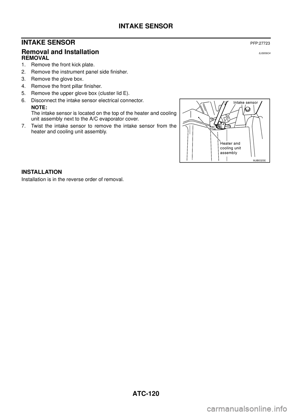
NOTE:
The intake sensor is located on the top of the heater and cooling
unit assembly next to the A/C evaporator cover.
7. Twist the intake sensor to remove the intake sensor from the
heater and cooling unit assembly.
INSTALLATION
Installation is in the reverse order of removal.
MJIB0325E