Page 1018 of 3171
EC-38
TROUBLE DIAGNOSIS
Basic Inspection
EBS01KCV
Precaution:
Perform Basic Inspection without electrical or mechanical loads applied;
lHeadlamp switch is OFF.
lOn vehicles equipped with daytime light systems, set lighting switch to the 1st position to light
only small lamps.
lAir conditioner switch is OFF.
lHeater fan switch is OFF.
lRear defogger switch is OFF.
lHeat up switch is OFF.
lSteering wheel is in the straight-ahead position, etc.
1.INSPECTION START
1. Check service records for any recent repairs that may indicate a related incident.
2. Check the current need for scheduled maintenance, especially for fuel filter and air cleaner filter. Refer to
MA-8, "
PERIODIC MAINTENANCE".
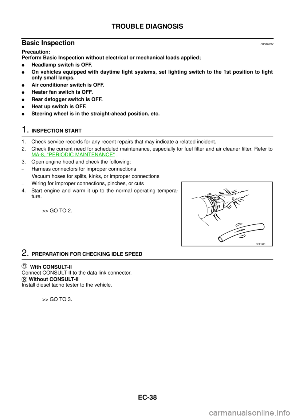
3. Open engine hood and check the following:
–Harness connectors for improper connections
–Vacuum hoses for splits, kinks, or improper connections
–Wiring for improper connections, pinches, or cuts
4. Start engine and warm it up to the normal operating tempera-
ture.
>> GO TO 2.
2.PREPARATION FOR CHECKING IDLE SPEED
With CONSULT-II
Connect CONSULT-II to the data link connector.
Without CONSULT-II
Install diesel tacho tester to the vehicle.
>> GO TO 3.
SEF142I
Page 1299 of 3171
HEAT UP SWITCH
EC-319
C
D
E
F
G
H
I
J
K
L
MA
EC
HEAT UP SWITCHPFP:27666
DescriptionEBS01KMA
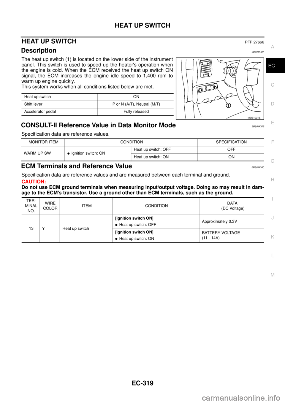
The heat up switch (1) is located on the lower side of the instrument
panel. This switch is used to speed up the heater's operation when
the engine is cold. When the ECM received the heat up switch ON
signal, the ECM increases the engine idle speed to 1,400 rpm to
warm up engine quickly.
This system works when all conditions listed below are met.
CONSULT-II Reference Value in Data Monitor ModeEBS01KMB
Specification data are reference values.
ECM Terminals and Reference ValueEBS01KMC
Specification data are reference values and are measured between each terminal and ground.
CAUTION:
Do not use ECM ground terminals when measuring input/output voltage. Doing so may result in dam-
age to the ECM's transistor. Use a ground other than ECM terminals, such as the ground.
Heat up switch ON
Shift lever P or N (A/T), Neutral (M/T)
Accelerator pedal Fully released
MBIB1221E
MONITOR ITEM CONDITION SPECIFICATION
WARM UP SW
lIgnition switch: ONHeat up switch: OFF OFF
Heat up switch: ON ON
TER-
MINAL
NO.WIRE
COLORITEM CONDITIONDATA
(DC Voltage)
13 Y Heat up switch[Ignition switch ON]
lHeat up switch: OFFApproximately 0.3V
[Ignition switch ON]
lHeat up switch: ONBATTERY VOLTAGE
(11 - 14V)
Page 1337 of 3171
SERVICE DATA AND SPECIFICATIONS (SDS)
EC-357
C
D
E
F
G
H
I
J
K
L
MA
EC
SERVICE DATA AND SPECIFICATIONS (SDS)PFP:00100
General SpecificationsEBS01KN4
*: Under the following conditions:
lHeat up switch: OFF
lAir conditioner switch: OFF
lElectric load: OFF (Lights, heater fan & rear window defogger)
lSteering wheel: Kept in straight-ahead position
Mass Air Flow SensorEBS01KN5
*: Engine is warmed up to normal operating temperature and running under no load.
Intake Air Temperature SensorEBS01KN6
Engine Coolant Temperature SensorEBS01KN7
Fuel Rail Pressure SensorEBS01KN8
Fuel InjectorEBS01KN9
Glow PlugEBS01KNA
EGR Volume Control ValveEBS01KNB
Crankshaft Position SensorEBS01KNC
Refer toEC-164, "Component Inspection".
Camshaft Position SensorEBS01KND
Refer toEC-175, "Component Inspection".
Target idle speedA/T No load* (in P or N position)
750±25 rpm
M/T No load* (in Neutral position)
Air conditioner: ONA/T In P or N position 750 rpm or more
M/T In Neutral position 800 rpm or more
Maximum engine speed4,900 rpm
Supply voltageBattery voltage (11 - 14V)
Ignition switch ON (Engine stopped.) Approx. 0.4V
Idle (Engine is warmed up to normal operating temperature.) 1.3 - 1.7V *
Temperature°C(°F) Resistance kW
25 (77)1.800 - 2.200
80 (176)0.283 - 0.359
Temperature°C(°F) Resistance kW
20 (68)2.1 - 2.9
50 (122)0.68 - 1.00
90 (194)0.236 - 0.260
Supply voltageApproximately 5V
Idle (Engine is warmed up to normal operating temperature.) 1.7 - 2.0V
2,000 rpm (Engine is warmed up to normal operating tempera-
ture.)2.0 - 2.3V
Resistance [at 10 - 60°C (50 - 140°F)] 0.2 - 0.8W
Resistance [at 25°C(77°F)] Approximately 0.8W
Resistance [at 25°C(77°F)] 13 - 17W
Page 1403 of 3171
INTAKE MANIFOLD
EM-21
C
D
E
F
G
H
I
J
K
L
MA
EM
lRefer toGI-10, "Components"for symbol marks except in the above.
Removal and InstallationEBS01EJF
REMOVAL
WARNING:
To avoid the danger of being scalded, do not drain engine coolant when engine is hot.
1. Drain engine coolant. Refer toCO-7, "
Changing Engine Coolant".
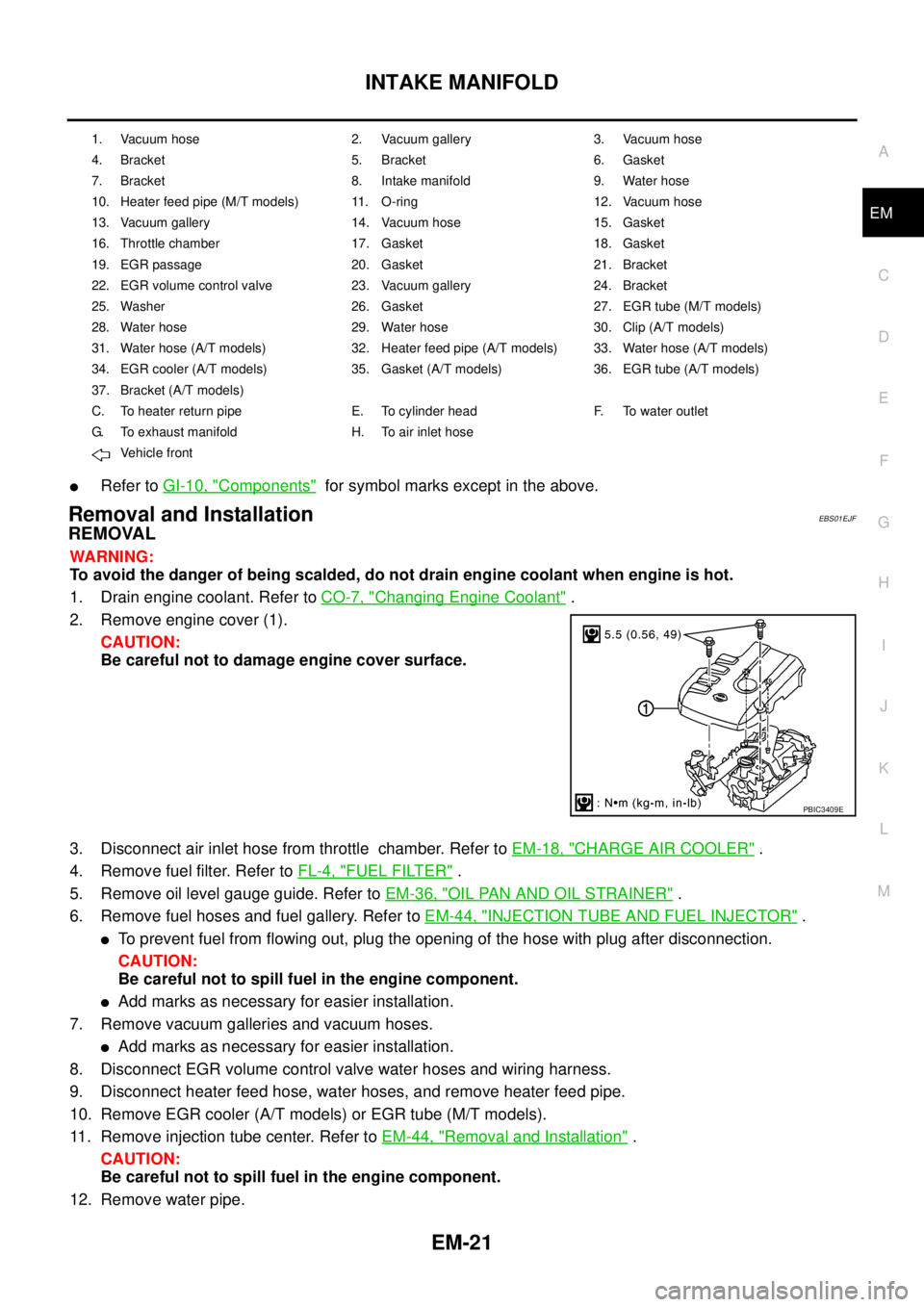
2. Remove engine cover (1).
CAUTION:
Be careful not to damage engine cover surface.
3. Disconnect air inlet hose from throttle chamber. Refer toEM-18, "
CHARGE AIR COOLER".
4. Remove fuel filter. Refer toFL-4, "
FUEL FILTER".
5. Remove oil level gauge guide. Refer toEM-36, "
OIL PAN AND OIL STRAINER".
6. Remove fuel hoses and fuel gallery. Refer toEM-44, "
INJECTION TUBE AND FUEL INJECTOR".
lTo prevent fuel from flowing out, plug the opening of the hose with plug after disconnection.
CAUTION:
Be careful not to spill fuel in the engine component.
lAdd marks as necessary for easier installation.
7. Remove vacuum galleries and vacuum hoses.
lAdd marks as necessary for easier installation.
8. Disconnect EGR volume control valve water hoses and wiring harness.
9. Disconnect heater feed hose, water hoses, and remove heater feed pipe.
10. Remove EGR cooler (A/T models) or EGR tube (M/T models).
11. Remove injection tube center. Refer toEM-44, "
Removal and Installation".
CAUTION:
Be careful not to spill fuel in the engine component.
12. Remove water pipe.
1. Vacuum hose 2. Vacuum gallery 3. Vacuum hose
4. Bracket 5. Bracket 6. Gasket
7. Bracket 8. Intake manifold 9. Water hose
10. Heater feed pipe (M/T models) 11. O-ring 12. Vacuum hose
13. Vacuum gallery 14. Vacuum hose 15. Gasket
16. Throttle chamber 17. Gasket 18. Gasket
19. EGR passage 20. Gasket 21. Bracket
22. EGR volume control valve 23. Vacuum gallery 24. Bracket
25. Washer 26. Gasket 27. EGR tube (M/T models)
28. Water hose 29. Water hose 30. Clip (A/T models)
31. Water hose (A/T models) 32. Heater feed pipe (A/T models) 33. Water hose (A/T models)
34. EGR cooler (A/T models) 35. Gasket (A/T models) 36. EGR tube (A/T models)
37. Bracket (A/T models)
C. To heater return pipe E. To cylinder head F. To water outlet
G. To exhaust manifold H. To air inlet hose
Vehicle front
PBIC3409E
Page 1405 of 3171
INTAKE MANIFOLD
EM-23
C
D
E
F
G
H
I
J
K
L
MA
EM
lInstall EGR cooler (A/T models).
–Tighten fixing bolts and nuts in numerical order as shown in the figure.
lInstall water hoses and heater feed hose.
1. EGR volume control valve 2. EGR tube
PBIC4105E
1. EGR volume control valve 2. EGR cooler 3. Bracket
4. EGR tube
PBIC4106E
Page 1406 of 3171
EM-24
INTAKE MANIFOLD
–Install water hose by referring to paint marks avoiding twisting.
–When an insert stopper is not provided with the pipe, insert the hose up to dimension A. When the pipe is
shorter than dimension A, insert hose fully until it reaches the end.
–When an insert stopper is provided on the pipe side, insert the hose until it reaches the stopper.
lInstall vacuum hoses.
–Install vacuum hose by referring to paint marks avoiding twisting.
1. Heater return pipe 2. Heater feed pipe 3. EGR volume control valve
4.EGR cooler (A/T models)
EGR tube (M/T models)5. Water outlet
A. Paint mark B. A/T models only
Vehicle front
Dimension A : 27 - 32 mm (1.063 - 1.260 in)
1. EGR volume control valve 2. Throttle chamber 3. Intake shutter control solenoid valve
A. Yellow paint B. White paint C. To brake booster
D. To vacuum pump Vehicle front
PBIC3412E
PBIC3899E
Page 1411 of 3171
TURBO CHARGER
EM-29
C
D
E
F
G
H
I
J
K
L
MA
EM
lRefer toGI-10, "Components"for symbol marks in the figure.
Removal and InstallationEBS01E5X
REMOVAL
lAfter applying penetrative lubricant to the mounting nuts, check for the penetration of the lubricant, and
then loosen the nuts to remove.
1. Drain engine coolant (4WD models). Refer toCO-7, "
Changing Engine Coolant".
2. Remove air inlet hose and air inlet pipe. Refer toEM-18, "
CHARGE AIR COOLER".
3. Remove air duct and air inlet pipes. Refer toEM-15, "
AIR CLEANER AND AIR DUCT".
4. Remove exhaust manifold cover. Refer toEM-34, "
EXHAUST MANIFOLD".
5. Remove exhaust outlet and catalyst. Refer toEM-26, "
CATALYST".
6. Remove eye bolt and water hose from water tube (4WD models).
7. Loosen and remove eye-bolts from oil feed tube.
8. Disconnect oil return hose from oil return tube.
9. Remove turbocharger with water tube (4WD models) and oil feed tube and oil return tube.
CAUTION:
Be careful not to deform water tube and oil feed tube and oil return tube.
10. Remove water tube (4WD models) and oil feed tube and oil return tube from turbocharger.
CAUTION:
lDo not disassemble or adjust the turbocharger.
lBe careful not to contact with the vehicle.
lDo not hold turbocharger boost control actuator and actuator rod.
Water Tube and Oil Tube
lClean inside of water tube (4WD models), oil feed tube and oil return tube, and check tubes for clogging.
lReplace water tube (4WD models), oil feed tube and/or oil return tube if clogging still exists after cleaning.
28. Oil return tube (2WD models)
A. To heater return pipe B. To cylinder block
Page 1431 of 3171
FUEL PUMP
EM-49
C
D
E
F
G
H
I
J
K
L
MA
EM
FUEL PUMPPFP:17042
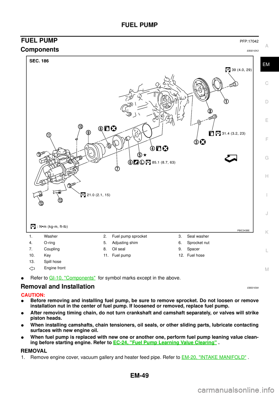
ComponentsEBS01EK3
lRefer toGI-10, "Components"for symbol marks except in the above.
Removal and InstallationEBS01E64
CAUTION:
lBefore removing and installing fuel pump, be sure to remove sprocket. Do not loosen or remove
installation nut in the center of fuel pump. If loosened or removed, replace fuel pump.
lAfter removing timing chain, do not turn crankshaft and camshaft separately, or valves will strike
piston heads.
lWhen installing camshafts, chain tensioners, oil seals, or other sliding parts, lubricate contacting
surfaces with new engine oil.
lWhen fuel pump is replaced with new one or another one, perform fuel pump leaning value clean-
ing before starting engine. Refer toEC-24, "
Fuel Pump Learning Value Clearing".
REMOVAL
1. Remove engine cover, vacuum gallery and heater feed pipe. Refer toEM-20, "INTAKE MANIFOLD".
1. Washer 2. Fuel pump sprocket 3. Seal washer
4. O-ring 5. Adjusting shim 6. Sprocket nut
7. Coupling 8. Oil seal 9. Spacer
10. Key 11. Fuel pump 12. Fuel hose
13. Spill hose
Engine front
PBIC3438E