2005 NISSAN NAVARA heater
[x] Cancel search: heaterPage 484 of 3171
ATC-150
REFRIGERANT LINES
CAUTION:
Replace the O-rings on the A/C low-pressure flexible A/C hose and the high-pressure A/C pipe with
new ones. Apply compressor oil to the O-rings for installation.
Removal and Installation for Expansion ValveEJS006CZ
REMOVAL
1. Discharge the refrigerant. Refer toATC-138, "HFC-134a (R-134a) Service Procedure".
2. Remove the heater and cooling unit assembly. Refer toATC-126, "
REMOVAL".
3. Remove the heater core and evaporator pipes grommet.
4. Remove the expansion valve.
INSTALLATION
Installation is in the reverse order of removal.
CAUTION:
lReplace the O-rings on then expansion valve and the A/C refrigerant pipes with new ones, then
apply compressor oil to them for installation.
lAfter charging refrigerant, check for leaks.
Checking for Refrigerant LeaksEJS006D1
Perform a visual inspection of all refrigeration parts, fittings, hoses and components for signs of A/C lubricant
leakage, damage and corrosion. A/C lubricant leakage may indicate an area of refrigerant leakage. Allow
extra inspection time in these areas when using either an electronic refrigerant leak detector or fluorescent
dye leak detector.
If dye is observed, confirm the leak with an electronic refrigerant leak detector. It is possible a prior leak was
repaired and not properly cleaned.
When searching for leaks, do not stop when one leak is found but continue to check for additional leaks at all
system components and connections.
When searching for refrigerant leaks using an electronic leak detector, move the probe along the suspected
leak area at 1 to 2 inches per second and no further than 1/4 inch from the component.
CAUTION:
Moving the electronic leak detector probe slower and closer to the suspected leak area will improve
the chances of finding a leak.
Checking System for Leaks Using the Fluorescent Leak DetectorEJS006D2
1. Check A/C system for leaks using the UV lamp and safety goggles [SST: J-42220] in a low sunlight area
(area without windows preferable). Illuminate all components, fittings and lines. The dye will appear as a
bright green/yellow area at the point of leakage. Fluorescent dye observed at the evaporator drain open-
ing indicates an evaporator core assembly (tubes, core or expansion valve) leak.
2. If the suspected area is difficult to see, use an adjustable mirror or wipe the area with a clean shop rag or
cloth, with the UV lamp for dye residue.
3. After the leak is repaired, remove any residual dye using dye cleaner [SST: J-43872] to prevent future mis-
diagnosis.
4. Perform a system performance check and verify the leak repair with an approved electronic refrigerant
leak detector.
NOTE:
Other gases in the work area or substances on the A/C components, for example, anti-freeze, windshield
washer fluid, solvents and lubricants, may falsely trigger the leak detector. Make sure the surfaces to be
checked are clean.
Cleanwithadryclothorblowoffwithshopair.
Do not allow the sensor tip of the detector to contact with any substance. This can also cause false readings
and may damage the detector.Expansion valve bolts : 4 N·m (0.41 kg-m, 35 in-lb)
A/C refrigerant pipe to expansion valve bolt : Refer toATC-140, "
Components"
.
Page 486 of 3171
ATC-152
REFRIGERANT LINES
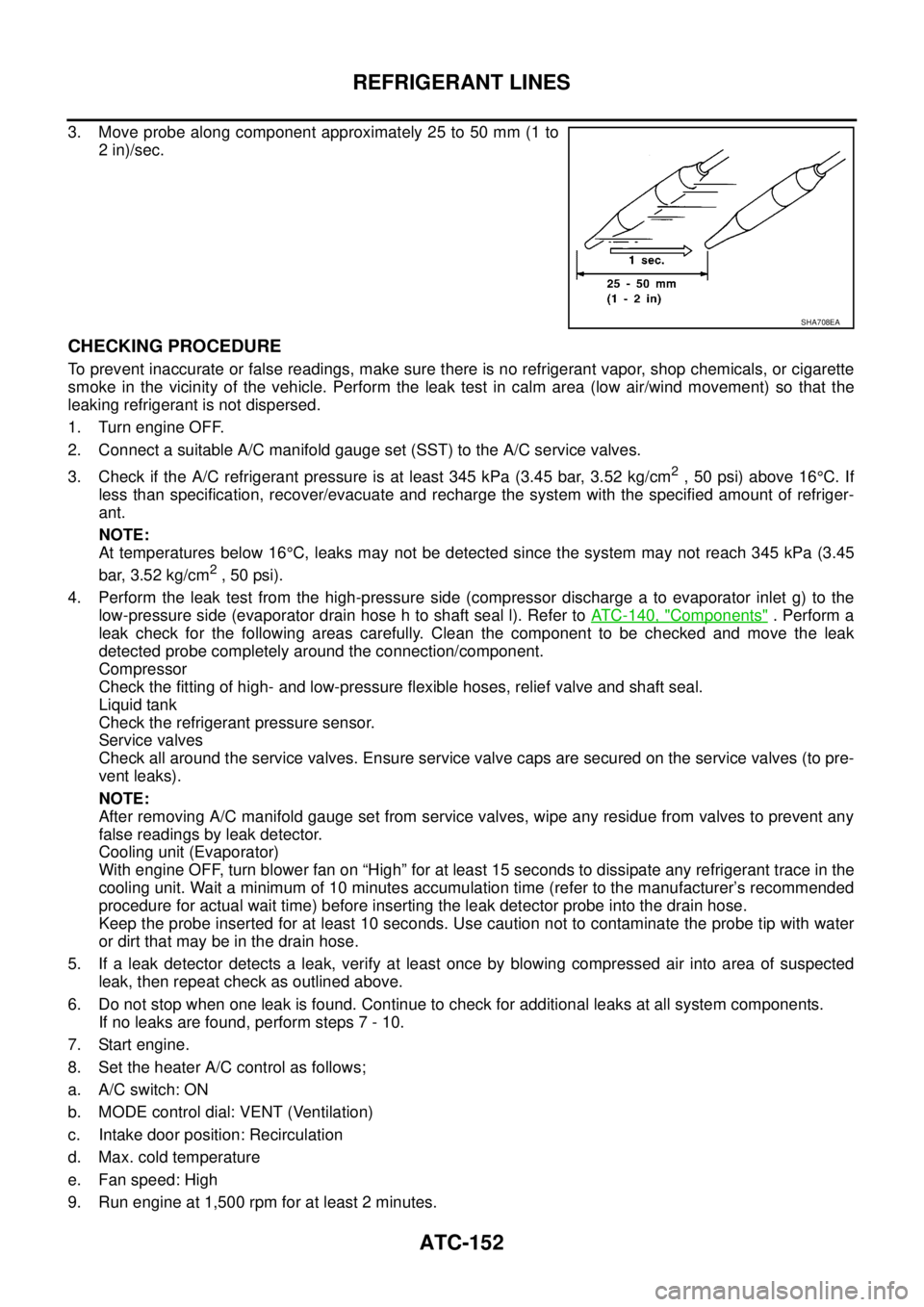
3. Move probe along component approximately 25 to 50 mm (1 to
2 in)/sec.
CHECKING PROCEDURE
To prevent inaccurate or false readings, make sure there is no refrigerant vapor, shop chemicals, or cigarette
smoke in the vicinity of the vehicle. Perform the leak test in calm area (low air/wind movement) so that the
leaking refrigerant is not dispersed.
1. Turn engine OFF.
2. Connect a suitable A/C manifold gauge set (SST) to the A/C service valves.
3. Check if the A/C refrigerant pressure is at least 345 kPa (3.45 bar, 3.52 kg/cm
2,50psi)above16°C. If
less than specification, recover/evacuate and recharge the system with the specified amount of refriger-
ant.
NOTE:
At temperatures below 16°C, leaks may not be detected since the system may not reach 345 kPa (3.45
bar, 3.52 kg/cm
2,50psi).
4. Perform the leak test from the high-pressure side (compressor discharge a to evaporator inlet g) to the
low-pressure side (evaporator drain hose h to shaft seal l). Refer toATC-140, "
Components". Perform a
leak check for the following areas carefully. Clean the component to be checked and move the leak
detected probe completely around the connection/component.
Compressor
Check the fitting of high- and low-pressure flexible hoses, relief valve and shaft seal.
Liquid tank
Check the refrigerant pressure sensor.
Service valves
Check all around the service valves. Ensure service valve caps are secured on the service valves (to pre-
vent leaks).
NOTE:
After removing A/C manifold gauge set from service valves, wipe any residue from valves to prevent any
false readings by leak detector.
Cooling unit (Evaporator)
With engine OFF, turn blower fan on “High” for at least 15 seconds to dissipate any refrigerant trace in the
cooling unit. Wait a minimum of 10 minutes accumulation time (refer to the manufacturer’s recommended
procedure for actual wait time) before inserting the leak detector probe into the drain hose.
Keep the probe inserted for at least 10 seconds. Use caution not to contaminate the probe tip with water
or dirt that may be in the drain hose.
5. If a leak detector detects a leak, verify at least once by blowing compressed air into area of suspected
leak, then repeat check as outlined above.
6. Do not stop when one leak is found. Continue to check for additional leaks at all system components.
If no leaks are found, perform steps 7 - 10.
7. Start engine.
8. Set the heater A/C control as follows;
a. A/C switch: ON
b. MODE control dial: VENT (Ventilation)
c. Intake door position: Recirculation
d. Max. cold temperature
e. Fan speed: High
9. Run engine at 1,500 rpm for at least 2 minutes.
SHA708EA
Page 892 of 3171
CO-8
ENGINE COOLANT
DRAINING ENGINE COOLANT
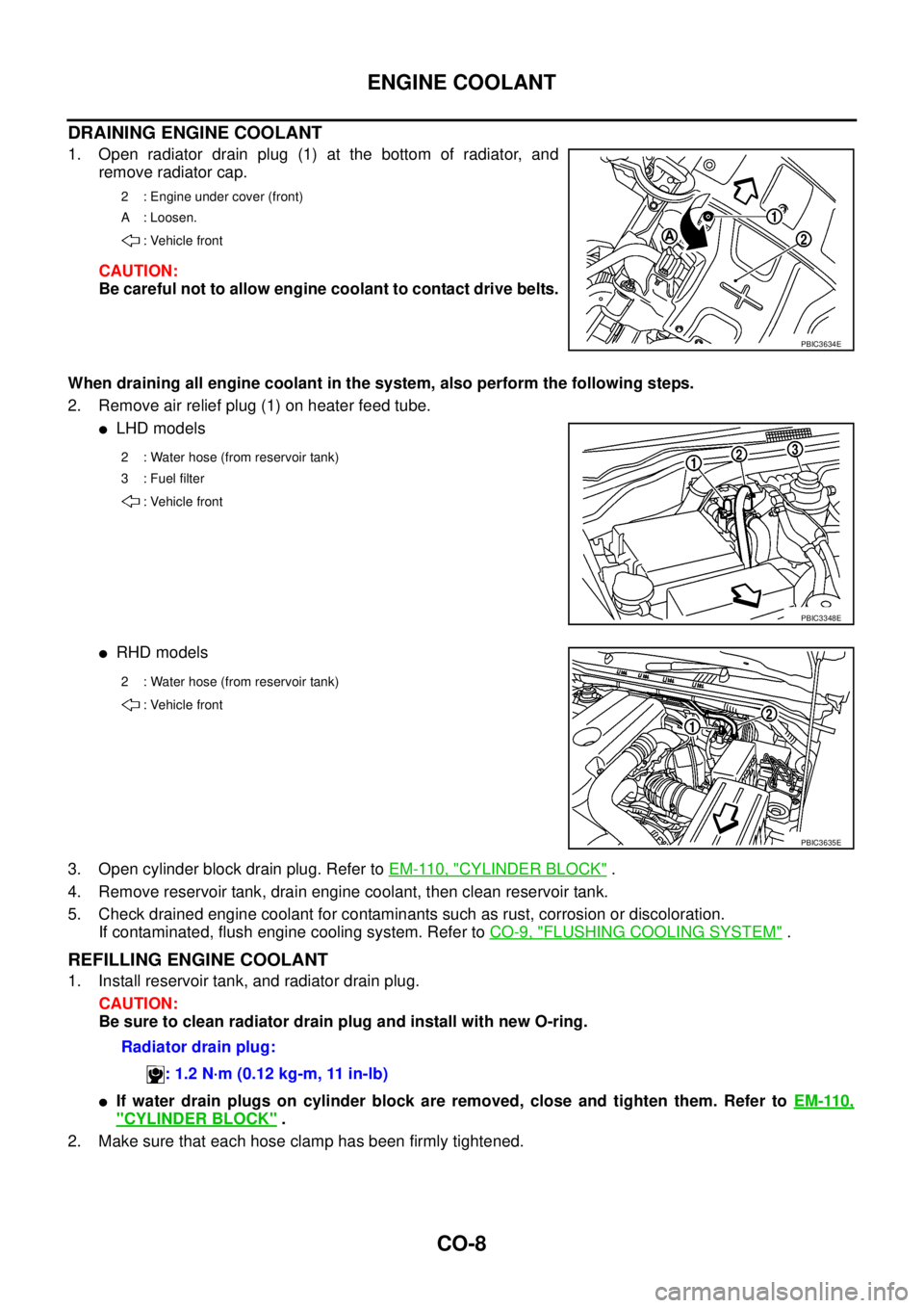
1. Open radiator drain plug (1) at the bottom of radiator, and
remove radiator cap.
CAUTION:
Be careful not to allow engine coolant to contact drive belts.
When draining all engine coolant in the system, also perform the following steps.
2. Remove air relief plug (1) on heater feed tube.
lLHD models
lRHD models
3. Open cylinder block drain plug. Refer toEM-110, "
CYLINDER BLOCK".
4. Remove reservoir tank, drain engine coolant, then clean reservoir tank.
5. Check drained engine coolant for contaminants such as rust, corrosion or discoloration.
If contaminated, flush engine cooling system. Refer toCO-9, "
FLUSHING COOLING SYSTEM".
REFILLING ENGINE COOLANT
1. Install reservoir tank, and radiator drain plug.
CAUTION:
Be sure to clean radiator drain plug and install with new O-ring.
lIf water drain plugs on cylinder block are removed, close and tighten them. Refer toEM-110,
"CYLINDER BLOCK".
2. Make sure that each hose clamp has been firmly tightened.
2 : Engine under cover (front)
A : Loosen.
: Vehicle front
PBIC3634E
2 : Water hose (from reservoir tank)
3 : Fuel filter
: Vehicle front
PBIC3348E
2 : Water hose (from reservoir tank)
: Vehicle front
PBIC3635E
Radiator drain plug:
: 1.2 N·m (0.12 kg-m, 11 in-lb)
Page 893 of 3171
ENGINE COOLANT
CO-9
C
D
E
F
G
H
I
J
K
L
MA
CO
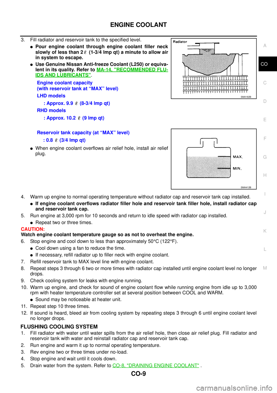
3. Fill radiator and reservoir tank to the specified level.
lPour engine coolant through engine coolant filler neck
slowly of less than 2 (1-3/4 lmp qt) a minute to allow air
in system to escape.
lUse Genuine Nissan Anti-freeze Coolant (L250) or equiva-
lent in its quality. Refer toMA-14, "
RECOMMENDED FLU-
IDS AND LUBRICANTS".
lWhen engine coolant overflows air relief hole, install air relief
plug.
4. Warm up engine to normal operating temperature without radiator cap and reservoir tank cap installed.
lIf engine coolant overflows radiator filler hole and reservoir tank filler hole, install radiator cap
and reservoir tank cap.
5. Run engine at 3,000 rpm for 10 seconds and return to idle speed with radiator cap installed.
lRepeat two or three times.
CAUTION:
Watch engine coolant temperature gauge so as not to overheat the engine.
6. Stop engine and cool down to less than approximately 50°C(122°F).
lCool down using a fan to reduce the time.
lIf necessary, refill radiator up to filler neck with engine coolant.
7. Refill reservoir tank to MAX level line with engine coolant.
8. Repeat steps 3 through 6 two or more times with radiator cap installed until engine coolant level no longer
drops.
9. Check cooling system for leaks with engine running.
10. Warm up engine, and check for sound of engine coolant flow while running engine from idle up to 3,000
rpm with heater temperature controller set at several position between COOL and WARM.
lSound may be noticeable at heater unit.
11. Repeat step 10 three times.
12. If sound is heard, bleed air from cooling system by repeating steps 3 through 6 until engine coolant level
no longer drops.
FLUSHING COOLING SYSTEM
1. Fill radiator with water until water spills from the air relief hole, then close air relief plug. Fill radiator and
reservoir tank with water and reinstall radiator cap and reservoir tank cap.
2. Run engine and warm it up to normal operating temperature.
3. Rev engine two or three times under no-load.
4. Stop engine and wait until it cools down.
5. Drain water from the system. Refer toCO-8, "
DRAINING ENGINE COOLANT". Engine coolant capacity
(with reservoir tank at “MAX” level)
LHD models
: Approx. 9.9 (8-3/4 lmp qt)
RHD models
: Approx. 10.2 (9 lmp qt)
SMA182B
Reservoir tank capacity (at “MAX” level)
: 0.8 (3/4 lmp qt)
SMA412B
Page 895 of 3171
RADIATOR
CO-11
C
D
E
F
G
H
I
J
K
L
MA
CO
RADIATORPFP:21400
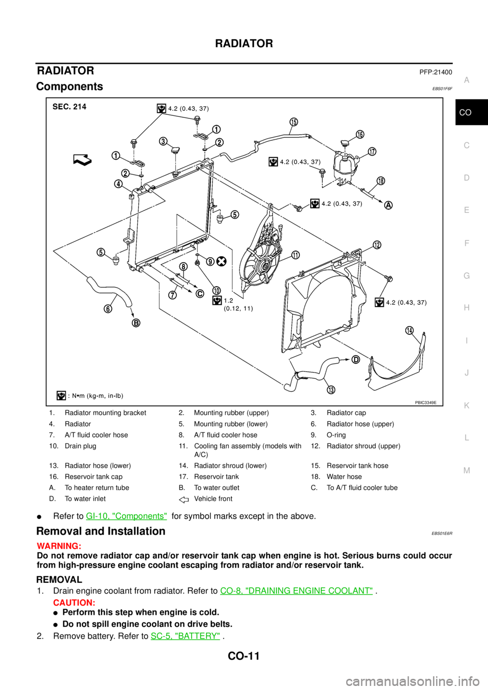
ComponentsEBS01F6F
lRefer toGI-10, "Components"for symbol marks except in the above.
Removal and InstallationEBS01E6R
WARNING:
Do not remove radiator cap and/or reservoir tank cap when engine is hot. Serious burns could occur
from high-pressure engine coolant escaping from radiator and/or reservoir tank.
REMOVAL
1. Drain engine coolant from radiator. Refer toCO-8, "DRAINING ENGINE COOLANT".
CAUTION:
lPerform this step when engine is cold.
lDo not spill engine coolant on drive belts.
2. Remove battery. Refer toSC-5, "
BATTERY".
1. Radiator mounting bracket 2. Mounting rubber (upper) 3. Radiator cap
4. Radiator 5. Mounting rubber (lower) 6. Radiator hose (upper)
7. A/T fluid cooler hose 8. A/T fluid cooler hose 9. O-ring
10. Drain plug 11. Cooling fan assembly (models with
A/C)12. Radiator shroud (upper)
13. Radiator hose (lower) 14. Radiator shroud (lower) 15. Reservoir tank hose
16. Reservoir tank cap 17. Reservoir tank 18. Water hose
A. To heater return tube B. To water outlet C. To A/T fluid cooler tube
D. To water inlet Vehicle front
PBIC3349E
Page 907 of 3171
THERMOSTAT AND WATER PIPING
CO-23
C
D
E
F
G
H
I
J
K
L
MA
CO
THERMOSTAT AND WATER PIPINGPFP:21200
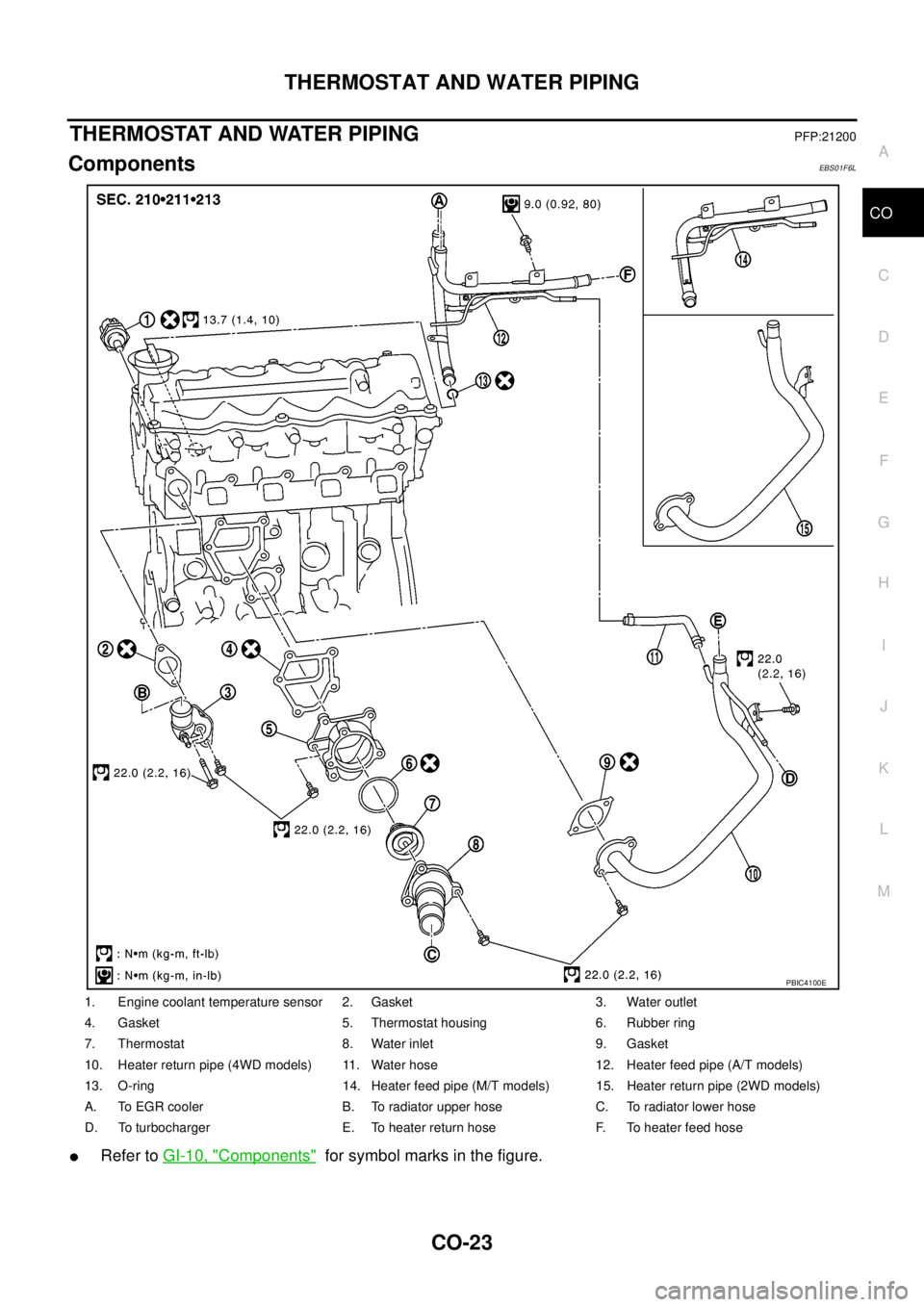
ComponentsEBS01F6L
lRefer toGI-10, "Components"for symbol marks in the figure.
1. Engine coolant temperature sensor 2. Gasket 3. Water outlet
4. Gasket 5. Thermostat housing 6. Rubber ring
7. Thermostat 8. Water inlet 9. Gasket
10. Heater return pipe (4WD models) 11. Water hose 12. Heater feed pipe (A/T models)
13. O-ring 14. Heater feed pipe (M/T models) 15. Heater return pipe (2WD models)
A. To EGR cooler B. To radiator upper hose C. To radiator lower hose
D. To turbocharger E. To heater return hose F. To heater feed hose
PBIC4100E
Page 908 of 3171
CO-24
THERMOSTAT AND WATER PIPING
Removal and Installation
EBS01E6X
WARNING:
Do not remove radiator cap and/or reservoir tank cap when engine is hot. Serious burns could occur
from high pressure engine coolant escaping from radiator and/or reservoir tank.
REMOVAL
1. Remove front engine undercover and middle engine undercover. Refer toEI-15, "FRONT BUMPER".
2. Drain engine coolant from radiator drain plug at the bottom of radiator, and from water drain plug at the
side of cylinder block. Refer toCO-7, "
Changing Engine Coolant"andEM-110, "CYLINDER BLOCK".
CAUTION:
Perform this step when engine is cold.
3. Remove engine cover. Refer toEM-20, "
INTAKE MANIFOLD".
4. Disconnect radiator hoses (upper and lower) from engine side. Refer toCO-11, "
RADIATOR".
5. Remove air inlet pipe and air duct between air cleaner case and turbocharger. Refer toEM-15, "
AIR
CLEANER AND AIR DUCT"andEM-28, "TURBO CHARGER".
6. Remove water outlet, water inlet and thermostat.
7. Remove thermostat housing.
8. Disconnect heater return hose and water hoses at heater return pipe side, and remove heater return pipe.
9. Remove oil level gauge guide mounting bolt, vacuum hoses (to turbocharger boost control solenoid valve)
and spill hose. Refer toEM-36, "
OIL PAN AND OIL STRAINER",EM-20, "INTAKE MANIFOLD"andEM-
44, "INJECTION TUBE AND FUEL INJECTOR".
10. Disconnect water hoses (to EGR cooler) (A/T models), vacuum hoses and heater feed hose at heater
feed pipe side, and remove heater feed pipe. Refer toEM-20, "
INTAKE MANIFOLD".
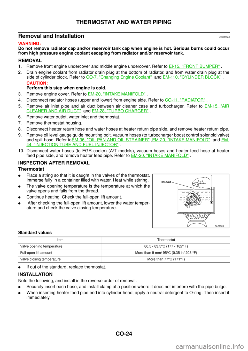
INSPECTION AFTER REMOVAL
Thermostat
lPlace a string so that it is caught in the valves of the thermostat.
Immerse fully in a container filled with water. Heat while stirring.
lThe valve opening temperature is the temperature at which the
valve opens and falls from the thread.
lContinue heating. Check the full-open lift amount.
lAfter checking the full-open lift amount, lower the water temper-
ature and check the valve closing temperature.
Standard values
lIf out of the standard, replace thermostat.
INSTALLATION
Note the following, and install in the reverse order of removal.
lSecurely insert each hose, and install clamp at a position where it does not interfere with the pipe bulge.
lWhen inserting heater feed pipe end into cylinder head, apply a neutral detergent to O-ring. Then insert it
immediately.
SLC252B
Item Thermostat
Valve opening temperature 80.5 - 83.5°C (177 - 182°F)
Full-open lift amount More than 9 mm/ 95°C (0.35 in/ 203°F)
Valve closing temperature More than 77°C(171°F)
Page 999 of 3171
ENGINE CONTROL SYSTEM
EC-19
C
D
E
F
G
H
I
J
K
L
MA
EC
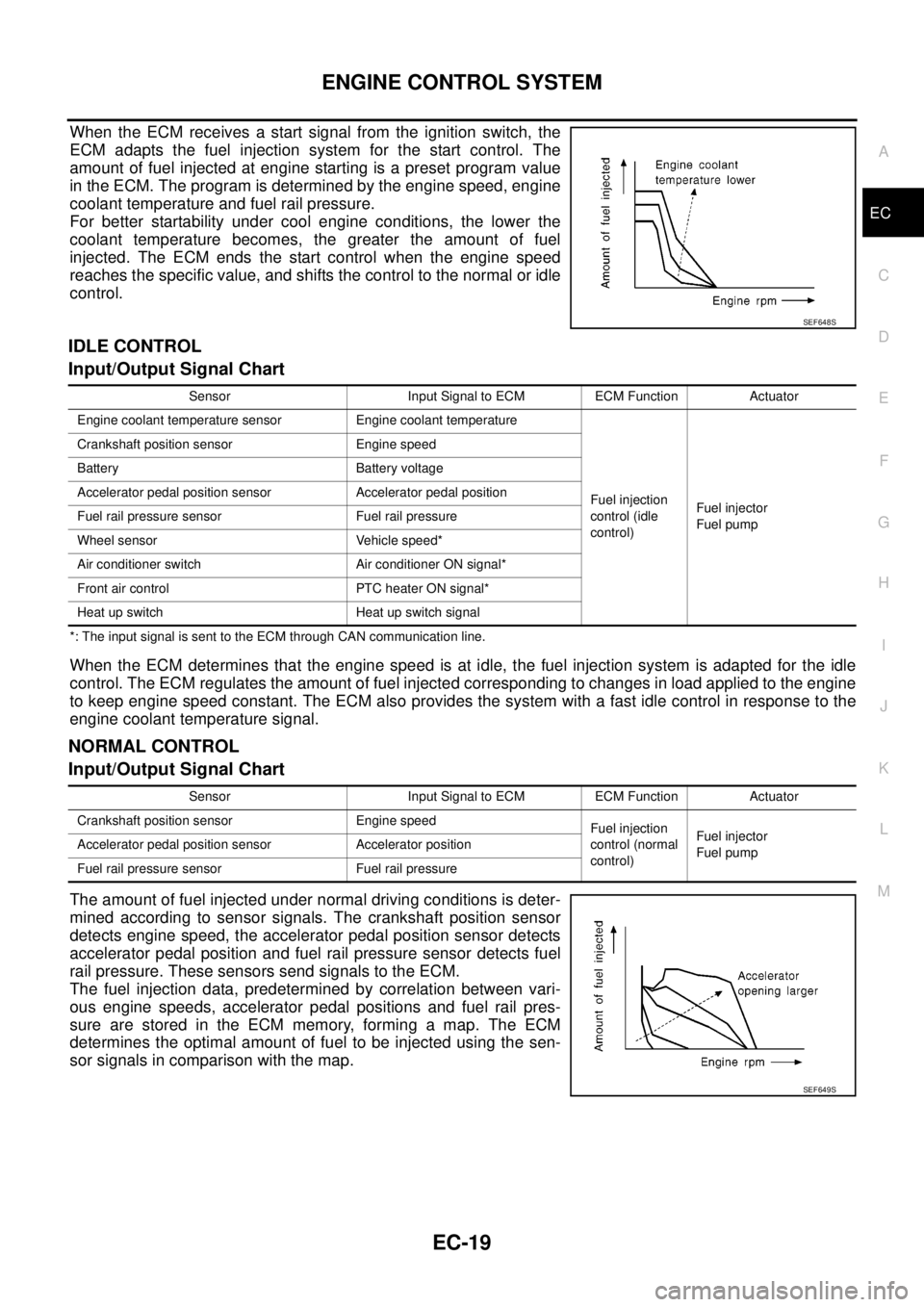
When the ECM receives a start signal from the ignition switch, the
ECM adapts the fuel injection system for the start control. The
amount of fuel injected at engine starting is a preset program value
in the ECM. The program is determined by the engine speed, engine
coolant temperature and fuel rail pressure.
For better startability under cool engine conditions, the lower the
coolant temperature becomes, the greater the amount of fuel
injected. The ECM ends the start control when the engine speed
reaches the specific value, and shifts the control to the normal or idle
control.
IDLE CONTROL
Input/Output Signal Chart
*: The input signal is sent to the ECM through CAN communication line.
When the ECM determines that the engine speed is at idle, the fuel injection system is adapted for the idle
control. The ECM regulates the amount of fuel injected corresponding to changes in load applied to the engine
to keep engine speed constant. The ECM also provides the system with a fast idle control in response to the
engine coolant temperature signal.
NORMAL CONTROL
Input/Output Signal Chart
The amount of fuel injected under normal driving conditions is deter-
mined according to sensor signals. The crankshaft position sensor
detects engine speed, the accelerator pedal position sensor detects
accelerator pedal position and fuel rail pressure sensor detects fuel
rail pressure. These sensors send signals to the ECM.
The fuel injection data, predetermined by correlation between vari-
ous engine speeds, accelerator pedal positions and fuel rail pres-
sure are stored in the ECM memory, forming a map. The ECM
determines the optimal amount of fuel to be injected using the sen-
sor signals in comparison with the map.
SEF648S
Sensor Input Signal to ECM ECM Function Actuator
Engine coolant temperature sensor Engine coolant temperature
Fuel injection
control (idle
control)Fuel injector
Fuel pump Crankshaft position sensor Engine speed
Battery Battery voltage
Accelerator pedal position sensor Accelerator pedal position
Fuel rail pressure sensor Fuel rail pressure
Wheel sensor Vehicle speed*
Air conditioner switch Air conditioner ON signal*
Front air control PTC heater ON signal*
Heat up switch Heat up switch signal
Sensor Input Signal to ECM ECM Function Actuator
Crankshaft position sensor Engine speed
Fuel injection
control (normal
control)Fuel injector
Fuel pump Accelerator pedal position sensor Accelerator position
Fuel rail pressure sensor Fuel rail pressure
SEF649S