Page 463 of 3171
INTAKE DOOR MOTOR
ATC-129
C
D
E
F
G
H
I
K
L
MA
B
AT C
INTAKE DOOR MOTORPFP:27730
ComponentsEJS006CD
Intake Door Motor - Heater and Cooling Unit Assembly
NOTE:
This illustration is for LHD models. The layout for RHD models is symmetrically opposite.
Removal and InstallationEJS006DD
REMOVAL
1. Remove the heater and cooling unit assembly. Refer toATC-124, "HEATER&COOLING UNIT ASSEM-
BLY".
2. Remove the steering member from the heater and cooling unit assembly.
3. Disconnect the intake door motor electrical connector.
4. Remove the three screws and remove the intake door motor.
INSTALLATION
Installation is in the reverse order of removal.
1. Heater and cooling unit assembly 2. Intake door motor 3. Air mix door motor (driver)
4. Variable blower control 5. Air mix door motor (passenger) 6. Mode door motor
LBIA0415E
Page 464 of 3171
ATC-130
MODE DOOR MOTOR
MODE DOOR MOTOR
PFP:27731
ComponentsEJS006CE
Mode Door Motor - Heater and Cooling Unit Assembly
NOTE:
This illustration is for LHD models. The layout for RHD models is symmetrically opposite.
Removal and InstallationEJS006DE
REMOVAL
1. Remove the instrument panel side finisher. Refer toIP-10, "INSTRUMENT PANEL ASSEMBLY".
2. Remove the lower instrument cover. Refer toIP-10, "
INSTRUMENT PANEL ASSEMBLY".
3. Disconnect the mode door motor electrical connector.
4. Remove the three screws and remove the mode door motor.
INSTALLATION
Installation is in the reverse order of removal.
1. Heater and cooling unit assembly 2. Intake door motor 3. Air mix door motor (driver)
4. Variable blower control 5. Air mix door motor (passenger) 6. Mode door motor
LBIA0415E
Page 465 of 3171

AIR MIX DOOR MOTOR
ATC-131
C
D
E
F
G
H
I
K
L
MA
B
AT C
AIR MIX DOOR MOTORPFP:27732
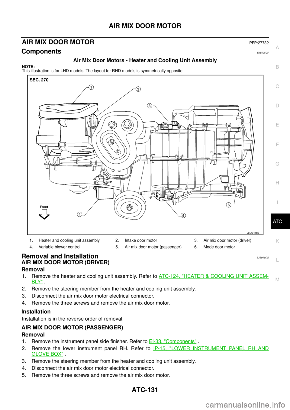
ComponentsEJS006CF
Air Mix Door Motors - Heater and Cooling Unit Assembly
NOTE:
This illustration is for LHD models. The layout for RHD models is symmetrically opposite.
Removal and InstallationEJS006CG
AIR MIX DOOR MOTOR (DRIVER)
Removal
1. Remove the heater and cooling unit assembly. Refer toATC-124, "HEATER&COOLING UNIT ASSEM-
BLY".
2. Remove the steering member from the heater and cooling unit assembly.
3. Disconnect the air mix door motor electrical connector.
4. Remove the three screws and remove the air mix door motor.
Installation
Installation is in the reverse order of removal.
AIR MIX DOOR MOTOR (PASSENGER)
Removal
1. Remove the instrument panel side finisher. Refer toEI-33, "Components".
2. Remove the lower instrument panel RH. Refer toIP-15, "
LOWER INSTRUMENT PANEL RH AND
GLOVE BOX".
3. Remove the steering member from the heater and cooling unit assembly.
4. Disconnect the air mix door motor electrical connector.
5. Remove the three screws and remove the air mix door motor.
1. Heater and cooling unit assembly 2. Intake door motor 3. Air mix door motor (driver)
4. Variable blower control 5. Air mix door motor (passenger) 6. Mode door motor
LBIA0415E
Page 467 of 3171
VARIABLE BLOWER CONTROL
ATC-133
C
D
E
F
G
H
I
K
L
MA
B
AT C
VARIABLE BLOWER CONTROLPFP:27200
ComponentsEJS006CH
Variable Blower Control - Heater and Cooling Unit Assembly
NOTE:
This illustration is for LHD models. The layout for RHD models is symmetrically opposite.
Removal and InstallationEJS006DF
REMOVAL
1. Disconnect the variable blower control electrical connector.
2. Remove the two screws and remove the variable blower control.
INSTALLATION
Installation is in the reverse order of removal.
1. Heater and cooling unit assembly 2. Intake door motor 3. Air mix door motor (driver)
4. Variable blower control 5. Air mix door motor (passenger) 6. Mode door motor
LBIA0415E
Page 468 of 3171
ATC-134
DUCTS AND GRILLES
DUCTS AND GRILLES
PFP:27860
ComponentsEJS006CJ
Ducts - Heater and Cooling Unit Assembly
MJIB0212E
1. Defroster nozzle 2. LH side demister duct 3. LH ventilator duct
4. RH side demister duct 5. RH ventilator duct 6. Center ventilator duct
7. Heater and cooling unit assembly 8. Floor connector duct grilles 9. Floor connector duct
Page 470 of 3171

ATC-136
DUCTS AND GRILLES
Removal and Installation
EJS006CK
CONSOLE DUCTS AND CONSOLE GRILLE
Removal
The center console must be removed and disassembled to remove the console ducts and the console grille.
Refer toIP-16, "
CENTER CONSOLE".
Installation
Installation is in the reverse order of removal.
DEFROSTER NOZZLE
Removal
1. Remove the instrument panel trim. Refer toIP-10, "Removal and Installation".
2. Remove the defroster nozzle.
Installation
Installation is in the reverse order of removal.
RH AND LH SIDE DEMISTER DUCT
Removal
1. Remove the instrument panel trim. Refer toIP-10, "Removal and Installation".
2. Remove the center console. Refer toIP-16, "
CENTER CONSOLE".
3. Remove the RH or LH side demister duct.
Installation
Installation is in the reverse order of removal.
RH AND LH VENTILATOR DUCT
Removal
1. Remove the instrument panel trim. Refer toIP-10, "Removal and Installation".
2. Remove the center console. Refer toIP-16, "
CENTER CONSOLE".
3. Remove the RH or LH ventilator duct.
Installation
Installation is in the reverse order of removal.
CENTER VENTILATOR DUCT
Removal
1. Remove the heater and cooling unit assembly. Refer toATC-126, "REMOVAL".
2. Remove the center console. Refer toIP-16, "
CENTER CONSOLE".
3. Remove the defroster nozzle.
4. Remove the RH and LH ventilator ducts.
5. Remove the RH and LH side demister ducts.
6. Remove the center ventilator duct.
Installation
Installation is in the reverse order of removal.
FLOOR CONNECTOR DUCT
Removal
1. Remove the heater and cooling unit assembly. Refer toATC-126, "REMOVAL".
2. Remove the center console. Refer toIP-16, "
CENTER CONSOLE".
3. Remove the floor connector duct.
Installation
Installation is in the reverse order of removal.
Page 481 of 3171

REFRIGERANT LINES
ATC-147
C
D
E
F
G
H
I
K
L
MA
B
AT C
CAUTION:
lReplace the O-ring of the low-pressure flexible A/C hose with a new one, then apply compressor
oil to it for installation.
lAfter charging refrigerant, check for leaks.
Removal and Installation for Low-pressure A/C PipeEJS006CS
REMOVAL
1. Discharge the refrigerant. Refer toATC-138, "HFC-134a (R-134a) Service Procedure".
2. Disconnect the heater pump connector.
3. Remove the heater pump from the bracket and reposition out of the way. Do not disconnect the heater
hoses from the heater pump.
4. Remove the low-pressure A/C pipe. Refer toATC-140, "
Components".
CAUTION:
Cap or wrap the joint of the pipe with suitable material such as vinyl tape to avoid the entry of air.
INSTALLATION
Installation is in the reverse order of removal.
Refer toATC-140, "
Components".
CAUTION:
lReplace the O-ring of the low-pressure A/C pipe with a new one, then apply compressor oil to it for
installation.
lAfter charging refrigerant, check for leaks.
Removal and Installation for Refrigerant Pressure SensorEJS006CV
REMOVAL
1. Discharge the refrigerant. Refer toATC-138, "HFC-134a (R-134a) Service Procedure".
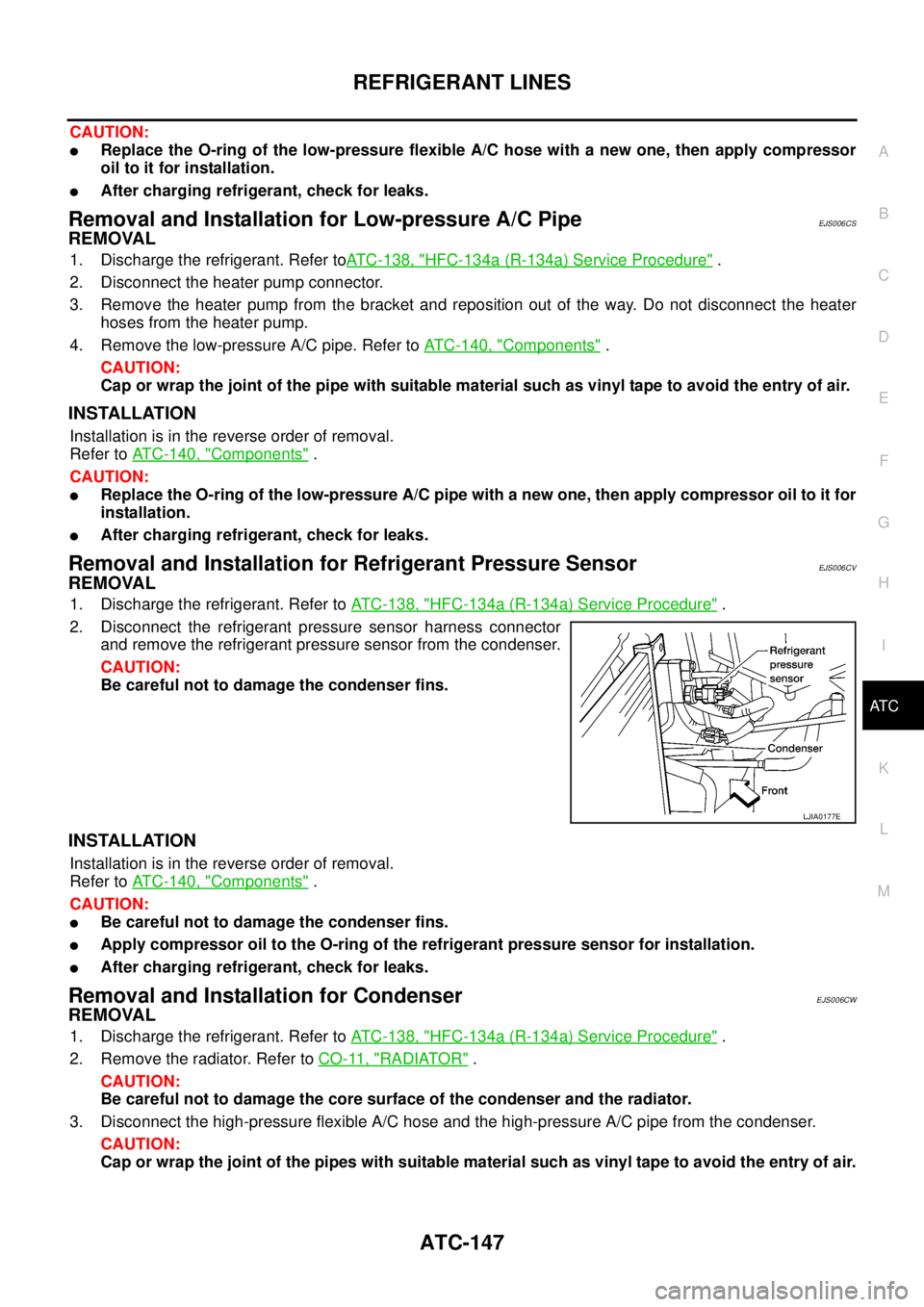
2. Disconnect the refrigerant pressure sensor harness connector
and remove the refrigerant pressure sensor from the condenser.
CAUTION:
Be careful not to damage the condenser fins.
INSTALLATION
Installation is in the reverse order of removal.
Refer toATC-140, "
Components".
CAUTION:
lBe careful not to damage the condenser fins.
lApply compressor oil to the O-ring of the refrigerant pressure sensor for installation.
lAfter charging refrigerant, check for leaks.
Removal and Installation for CondenserEJS006CW
REMOVAL
1. Discharge the refrigerant. Refer toATC-138, "HFC-134a (R-134a) Service Procedure".
2. Remove the radiator. Refer toCO-11, "
RADIATOR".
CAUTION:
Be careful not to damage the core surface of the condenser and the radiator.
3. Disconnect the high-pressure flexible A/C hose and the high-pressure A/C pipe from the condenser.
CAUTION:
Cap or wrap the joint of the pipes with suitable material such as vinyl tape to avoid the entry of air.
LJIA0177E
Page 483 of 3171
REFRIGERANT LINES
ATC-149
C
D
E
F
G
H
I
K
L
MA
B
AT C
Removal and Installation for EvaporatorEJS006CX
Heater and Cooling Unit Assembly
REMOVAL
1. Remove the heater core. Refer toATC-127, "REMOVAL".
2. Separate the heater and cooling unit case.
3. Remove the evaporator.
INSTALLATION
Installation is in the reverse order of removal.
MJIB0214E
1. Center ventilator connector duct 2. Heater core cover 3. Intake air case
4. Heater core and evaporator pipes
bracket5. Heater core and evaporator pipes
grommet6. Heater core
7. Upper heater and cooling unit case 8. Expansion valve 9. Evaporator
10. Lower heater and cooling unit case 11. Variable blower control 12. Blower motor