2005 NISSAN NAVARA heater
[x] Cancel search: heaterPage 1478 of 3171
EM-96
CYLINDER HEAD
INSTALLATION
Before installation, remove old liquid gasket from mating surface of all liquid gasket applied parts.
1. Install cylinder head gasket.
lCylinder head gasket to be installed is selected by its thickness through the following procedure.
–When replacing gasket alone
• Install a gasket with same thickness as that of the one removed.
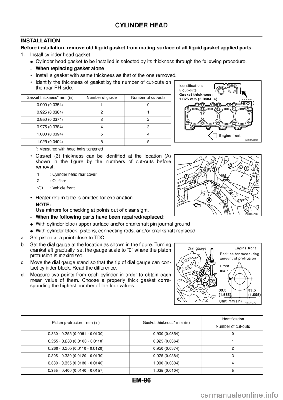
• Identify the thickness of gasket by the number of cut-outs on
the rear RH side.
*: Measured with head bolts tightened
• Gasket (3) thickness can be identified at the location (A)
shown in the figure by the numbers of cut-outs before
removal.
• Heater return tube is omitted for explanation.
NOTE:
Use mirrors for checking at points out of clear sight.
–When the following parts have been repaired/replaced:
lWith cylinder block upper surface and/or crankshaft pin journal ground
lWith cylinder block, pistons, connecting rods, and/or crankshaft replaced
a. Set piston at a point close to TDC.
b. Set the dial gauge at the location as shown in the figure. Turning
crankshaft gradually, set the gauge scale to “0” where the piston
protrusion is maximized.
c. Movethedialgaugestandsothatthetipofdialgaugecancon-
tact cylinder block. Read the difference.
d. Measure two points from each cylinder in order to obtain each
mean value of them. Choose a properly thick gasket corre-
sponding the highest number of the four values.
Gasket thickness* mm (in) Number of grade Number of cut-outs
0.900 (0.0354) 1 0
0.925 (0.0364) 2 1
0.950 (0.0374) 3 2
0.975 (0.0384) 4 3
1.000 (0.0394) 5 4
1.025 (0.0404) 6 5
1 : Cylinder head rear cover
2:Oilfilter
: Vehicle front
MBIA0020E
PBIC3478E
SEM507G
Piston protrusion mm (in) Gasket thickness* mm (in)Identification
Number of cut-outs
0.230 - 0.255 (0.0091 - 0.0100) 0.900 (0.0354) 0
0.255 - 0.280 (0.0100 - 0.0110) 0.925 (0.0364) 1
0.280 - 0.305 (0.0110 - 0.0120) 0.950 (0.0374) 2
0.305 - 0.330 (0.0120 - 0.0130) 0.975 (0.0384) 3
0.330 - 0.355 (0.0130 - 0.0140) 1.000 (0.0394) 4
0.355 - 0.400 (0.0140 - 0.0157) 1.025 (0.0404) 5
Page 1489 of 3171
ENGINE ASSEMBLY
EM-107
C
D
E
F
G
H
I
J
K
L
MA
EM
lFor supporting points for lifting and jacking point at rear axle, refer toGI-52, "Pantograph Jack,
Garage Jack and Safety Stand".
REMOVAL
Description of work
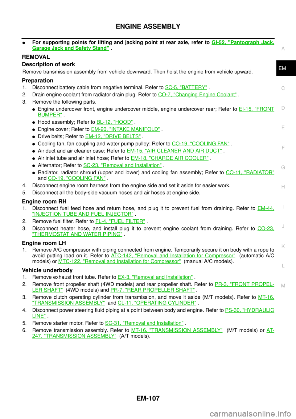
Remove transmission assembly from vehicle downward. Then hoist the engine from vehicle upward.
Preparation
1. Disconnect battery cable from negative terminal. Refer toSC-5, "BATTERY".
2. Drain engine coolant from radiator drain plug. Refer toCO-7, "
Changing Engine Coolant".
3. Remove the following parts.
lEngine undercover front, engine undercover middle, engine undercover rear; Refer toEI-15, "FRONT
BUMPER".
lHood assembly; Refer toBL-12, "HOOD".
lEngine cover; Refer toEM-20, "INTAKE MANIFOLD".
lDrive belts; Refer toEM-12, "DRIVE BELTS".
lCooling fan, fan coupling and water pump pulley; Refer toCO-19, "COOLING FAN".
lAir duct and air cleaner case; Refer toEM-15, "AIR CLEANER AND AIR DUCT".
lAir inlet tube and air inlet hose; Refer toEM-18, "CHARGE AIR COOLER".
lAlternator; Refer toSC-23, "Removal and Installation".
lRadiator, radiator shroud (upper and lower) and cooling fan assembly; Refer toCO-11, "RADIATOR"
andCO-19, "COOLING FAN".
4. Disconnect engine room harness from the engine side and set it aside for easier work.
5. Disconnect all the body-side vacuum hoses and air hoses at engine side.
Engine room RH
1. Disconnect fuel feed hose and return hose, and plug it to prevent fuel from draining. Refer toEM-44,
"INJECTION TUBE AND FUEL INJECTOR".
2. Remove fuel filter. Refer toFL-4, "
FUEL FILTER".
3. Disconnect heater hose, and install plug it to prevent engine coolant from draining. Refer toCO-23,
"THERMOSTAT AND WATER PIPING".
Engine room LH
1. Remove A/C compressor with piping connected from engine. Temporarily secure it on body with a rope to
avoid putting load on it. Refer toATC-142, "
Removal and Installation for Compressor"(automatic A/C
models) orMTC-122, "
Removal and Installation for Compressor"(manual A/C models).
Vehicle underbody
1. Remove exhaust front tube. Refer toEX-3, "Removal and Installation".
2. Remove front propeller shaft (4WD models) and rear propeller shaft. Refer toPR-3, "
FRONT PROPEL-
LER SHAFT"(4WD models) andPR-7, "REAR PROPELLER SHAFT".
3. Remove clutch operating cylinder from transmission, and move it aside (M/T models). Refer toMT-16,
"TRANSMISSION ASSEMBLY"andCL-11, "OPERATING CYLINDER".
4. Disconnect power steering fluid piping at a point between body and engine. Refer toPS-30, "
HYDRAULIC
LINE".
5. Remove starter motor. Refer toSC-31, "
Removal and Installation".
6. Remove transmission assembly. Refer toMT-16, "
TRANSMISSION ASSEMBLY"(M/T models) orAT-
247, "TRANSMISSION ASSEMBLY"(A/T models).
Page 1683 of 3171
TERMINOLOGY
GI-61
C
D
E
F
G
H
I
J
K
L
MB
GI
TERMINOLOGYPFP:00011
ISO 15031-2 Terminology ListEAS001H9
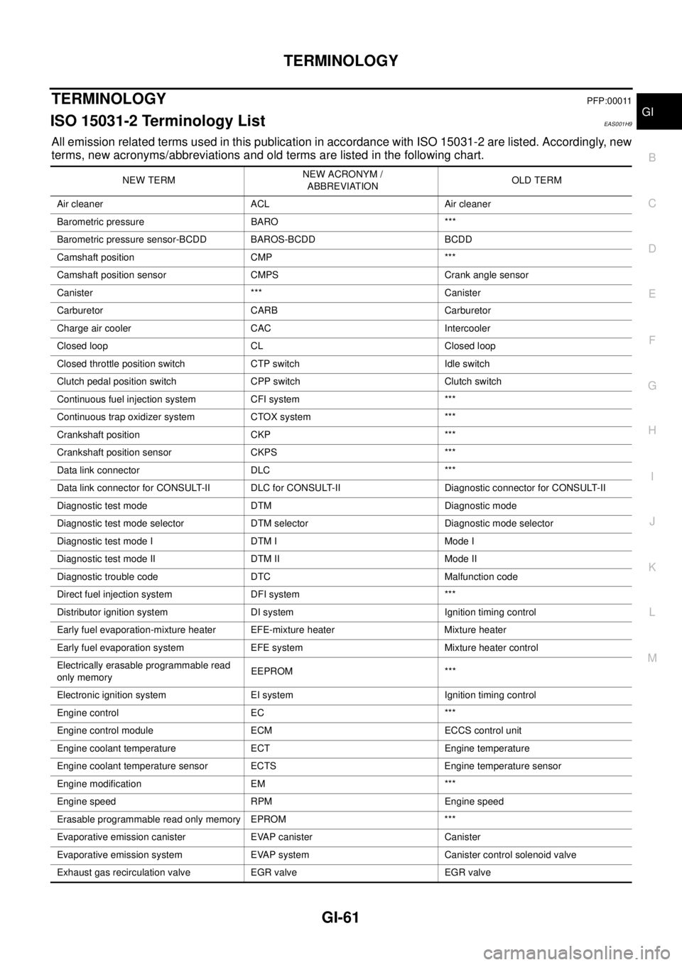
All emission related terms used in this publication in accordance with ISO 15031-2 are listed. Accordingly, new
terms, new acronyms/abbreviations and old terms are listed in the following chart.
NEW TERMNEW ACRONYM /
ABBREVIATIONOLD TERM
Air cleaner ACL Air cleaner
Barometric pressure BARO ***
Barometric pressure sensor-BCDD BAROS-BCDD BCDD
Camshaft position CMP ***
Camshaft position sensor CMPS Crank angle sensor
Canister *** Canister
Carburetor CARB Carburetor
Charge air cooler CAC Intercooler
Closed loop CL Closed loop
Closed throttle position switch CTP switch Idle switch
Clutch pedal position switch CPP switch Clutch switch
Continuous fuel injection system CFI system ***
Continuous trap oxidizer system CTOX system ***
Crankshaft position CKP ***
Crankshaft position sensor CKPS ***
Data link connector DLC ***
Data link connector for CONSULT-II DLC for CONSULT-II Diagnostic connector for CONSULT-II
Diagnostic test mode DTM Diagnostic mode
Diagnostic test mode selector DTM selector Diagnostic mode selector
Diagnostic test mode I DTM I Mode I
Diagnostic test mode II DTM II Mode II
Diagnostic trouble code DTC Malfunction code
Direct fuel injection system DFI system ***
Distributor ignition system DI system Ignition timing control
Early fuel evaporation-mixture heater EFE-mixture heater Mixture heater
Early fuel evaporation system EFE system Mixture heater control
Electrically erasable programmable read
only memoryEEPROM ***
Electronic ignition system EI system Ignition timing control
Engine control EC ***
Engine control module ECM ECCS control unit
Engine coolant temperature ECT Engine temperature
Engine coolant temperature sensor ECTS Engine temperature sensor
Engine modification EM ***
Engine speed RPM Engine speed
Erasable programmable read only memory EPROM ***
Evaporative emission canister EVAP canister Canister
Evaporative emission system EVAP system Canister control solenoid valve
Exhaust gas recirculation valve EGR valve EGR valve
Page 1751 of 3171
DOOR MIRROR
GW-65
C
D
E
F
G
H
J
K
L
MA
B
GW
Door Mirror AssemblyEIS00B8Z
REMOVAL
NOTE:
Be careful not to damage the mirror bodies.
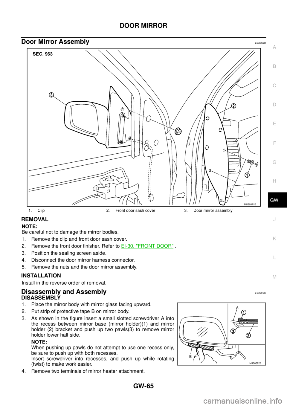
1. Remove the clip and front door sash cover.
2. Remove the front door finisher. Refer toEI-30, "
FRONT DOOR".
3. Position the sealing screen aside.
4. Disconnect the door mirror harness connector.
5. Remove the nuts and the door mirror assembly.
INSTALLATION
Install in the reverse order of removal.
Disassembly and AssemblyEIS00C06
DISASSEMBLY
1. Place the mirror body with mirror glass facing upward.
2. Put strip of protective tape B on mirror body.
3. As shown in the figure insert a small slotted screwdriver A into
the recess between mirror base (mirror holder)(1) and mirror
holder (2) bracket and push up two pawls(3) to remove mirror
holder lower half side.
NOTE:
When pushing up pawls do not attempt to use one recess only,
be sure to push up with both recesses.
Insert screwdriver into recesses, and push up while rotating
(twist) to make work easier.
4. Remove two terminals of mirror heater attachment.
1. Clip 2. Front door sash cover 3. Door mirror assembly
MIIB0571E
MIIB0572E
Page 1752 of 3171
GW-66
DOOR MIRROR
5. Lightly lift up lower side of mirror surface from mirror surface, and detach two pawls of upper side as if
pulling it out. Remove mirror surface from mirror body.
NOTE:
Be certain not to allow grease on sealing agent in center of mirror body assembly (actuator) or back side of
mirror surface (mirror holder).
ASSEMBLY
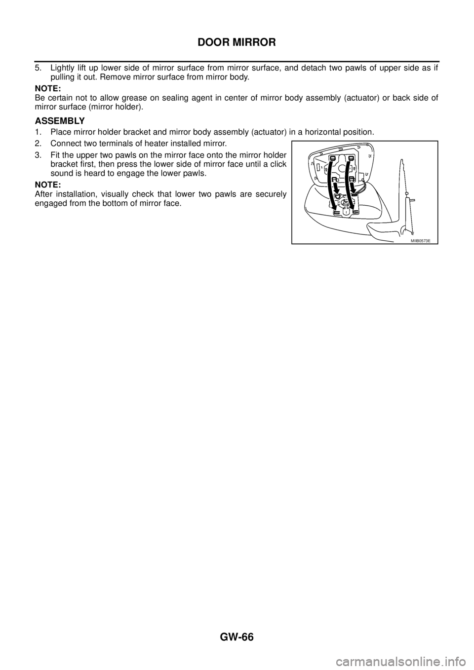
1. Place mirror holder bracket and mirror body assembly (actuator) in a horizontal position.
2. Connect two terminals of heater installed mirror.
3. Fit the upper two pawls on the mirror face onto the mirror holder
bracket first, then press the lower side of mirror face until a click
sound is heard to engage the lower pawls.
NOTE:
After installation, visually check that lower two pawls are securely
engaged from the bottom of mirror face.
MIIB0573E
Page 1756 of 3171
IDX-4
ALPHABETICAL INDEX
Engine control system diagram and chart .........EC-15
Engine coolant ....................................................CO-7
Engine coolant temperature sensor (ECTS) ....EC-103
Engine oil .............................................................LU-5
Engine oil filter replacement .............................MA-26
Engine oil precautions ..........................................GI-7
Engine removal ...............................................EM-106
Engine room cover ............................................EM-20
Engine serial number ..........................................GI-58
Evaporator ....................................ATC-149,MTC-129
Exhaust manifold ..............................................EM-34
Exhaust system ...................................................EX-2
Exhaust system inspection ..................................EX-2
Expansion valve ............................ATC-150,MTC-130
F
F/FOG - Wiring diagram .....................................LT-74
F/PUMP - Wiring diagram ..EC-248,EC-254,EC-260,
EC-266
Final drive pre-inspection .................................FFD-18
Final drive removal and installation ..RFD-14,RFD-81
Flow charts .........................................................GI-24
Fluid temperature sensor (A/T) ........................AT-118
Fluids ................................................................MA-14
Fluorescent leak detector .............ATC-150,MTC-131
Flywheel (clutch) ................................................CL-17
Flywheel runout ..............................................EM-134
Fog lamp, front ....................................................LT-71
Foot lamp ..........................................................LT-145
Fork rod (M/T) ....................................................MT-23
Freeze frame data .............................................EC-28
Front brake solenoid valve .................AT-137,AT-139
Front bumper ......................................................EI-15
Front case (Transfer) ..........................TF-114,TF-120
Front combination lamp removal and installationLT-30
Front door ................BL-118,BL-120,BL-126,GW-35
Front Door Trim ..................................................EI-30
Front drive shaft (Transfer) ...TF-114,TF-120,TF-133
Front final drive removal and installation (4WD) ...........
FFD-15
Front fog lamp .....................................................LT-71
Front passenger air bag ..................................SRS-40
Front seat ...........................................................SE-20
Front seat belt ............................................SB-3,SB-5
Front seat belt pre-tensioner ...............SRS-3,SRS-47
Front side air bag ............................................SRS-43
Front washer ......................................................WW-4
Front wiper .........................................................WW-4
FRPS - Wiring diagram ....................................EC-120
FTS - Wiring diagram .......................................EC-115
Fuel cut control (at no load high engine speed) .EC-20
Fuel filler lid ......................................................BL-136
Fuel filter ............................................................EC-23
Fuel filter replacement ..........................................FL-4
Fuel gauge ............................................................DI-4
Fuel injection control system .............................EC-18
Fuel injector ............EC-25,EC-123,EC-125,EC-237
Fuel injector and fuel tube ................................EM-44
Fuel leak ............................................................EC-88
Fuel line inspection ..............................................FL-3
Fuel pumpEC-86,EC-217,EC-245,EC-251,EC-258,
EC-263
Fuel pump(Learning Value Clearing) .................EC-24
Fuel rail pressure sensor .................................EC-118
Fuel system .........................................................FL-3
Fuel tank ..............................................................FL-9
Fuel temperature sensor ..................................EC-113
Fuse ......................................................PG-74,PG-84
Fuse and fusible link box ..................................PG-84
Fusible link ............................................PG-74,PG-84
G
Garage jack and safety stand .............................GI-52
Gauges .................................................................DI-4
Gear components (M/T) ....................................MT-21
Generator ...........................................................SC-14
Generator - See Alternator ................................SC-14
Glass ........................GW-11,GW-35,GW-38,GW-43
Glove box lamp ................................................LT-162
GLOW - Wiring diagram ..................................EC-296
Glow plug ............................................EM-41,EC-295
Glow relay ........................................................EC-295
Grease ..............................................................MA-14
Ground distribution ...........................................PG-27
H
H/AIM - Wiring diagram .....................................LT-66
Harness connector ............................................PG-75
Harness layout ..................................................PG-38
Hazard warning lamp .........................................LT-97
Headlamp aiming control ...................................LT-66
Headlamp leveler - See Headlamp aiming control ........
LT-66
Headlamp removal and installation ....................LT-30
Heat up switch .................................................EC-319
Heated seat .......................................................SE-12
Heater and cooling unit (Heater core) ..........ATC-124,
ATC-127
,MTC-103,MTC-106
Heater unit (heater core) ..............ATC-124,ATC-127,
MTC-103
,MTC-106
HEATUP - Wiring diagram ...............................EC-320
Height (Dimensions) ...........................................GI-60
HFC134a (R134a) system precaution .ATC-4,MTC-4
HFC134a (R134a) system service procedureATC-138,
MTC-118
HFC134a (R134a) system service tools ........ATC-16,
MTC-16
HFC134a system service equipment precaution ..........
ATC-12
,MTC-12
High and low reverse clutch solenoid valve ....AT-147,
AT-149
HLC - Wiring diagram ......................................WW-41
Horn .................................................................WW-59
HORN - Wiring diagram ...................................WW-59
How to erase DTC .............................................EC-27
Page 1810 of 3171
![NISSAN NAVARA 2005 Repair Workshop Manual CAN COMMUNICATION
LAN-33
[CAN]
C
D
E
F
G
H
I
J
L
MA
B
LAN
Input/output signal chart
T: Transmit R: Receive
Signals ECMNAVI con-
trol unitFront air
controlBCMCombina-
tion meterABS actua-
tor and
elect NISSAN NAVARA 2005 Repair Workshop Manual CAN COMMUNICATION
LAN-33
[CAN]
C
D
E
F
G
H
I
J
L
MA
B
LAN
Input/output signal chart
T: Transmit R: Receive
Signals ECMNAVI con-
trol unitFront air
controlBCMCombina-
tion meterABS actua-
tor and
elect](/manual-img/5/57362/w960_57362-1809.png)
CAN COMMUNICATION
LAN-33
[CAN]
C
D
E
F
G
H
I
J
L
MA
B
LAN
Input/output signal chart
T: Transmit R: Receive
Signals ECMNAVI con-
trol unitFront air
controlBCMCombina-
tion meterABS actua-
tor and
electric unit
(control
unit)IPDM E/R
A/C compressor request signal TR
ASCD CRUISE lamp signal T R
ASCD SET lamp signal T R
Cooling fan speed request signal TR
Engine coolant temperature signal T R R
Engine speed signal T R R
Engine status signal T R R
Fuel consumption monitor signalTR
RT
Glow indicator signal T R
Glow relay signal T R
Malfunction indicator signal T R
A/C switch/indicator signal T
R
*
PTC heater signal R T
A/C switch signal R
R
*T
Buzzer output signal T R
Day time running light request signal R T R R
Door switch signal T R R
Front fog light request signal R T R R
Front wiper request signal T R
High beam request signal T R R
Horn chirp signal T R
Low beam request signal T R
Position light request signal T R R
Rear fog light request signal R T R
Rear window defogger switch signal
R
*TR
Sleep wake up signal T R R
Theft warning horn request signal T R
Trailer lamp signal T R
Turn indicator signal T R
Distance to empty signal R T
Fuel level low warning signal R T
ABS warning lamp signalRT
Vehicle speed signalR
*RT
RR
R
*RT
Front wiper stop position signal R T
Hood switch signal R T
Oil pressure switch signalRT
Rear window defogger control signal R T
Page 1812 of 3171
![NISSAN NAVARA 2005 Repair Workshop Manual CAN COMMUNICATION
LAN-35
[CAN]
C
D
E
F
G
H
I
J
L
MA
B
LAN
Closed throttle position signal T R
Cooling fan speed request signal TR
Engine coolant temperature signal T R R
Engine speed signal T R R R
En NISSAN NAVARA 2005 Repair Workshop Manual CAN COMMUNICATION
LAN-35
[CAN]
C
D
E
F
G
H
I
J
L
MA
B
LAN
Closed throttle position signal T R
Cooling fan speed request signal TR
Engine coolant temperature signal T R R
Engine speed signal T R R R
En](/manual-img/5/57362/w960_57362-1811.png)
CAN COMMUNICATION
LAN-35
[CAN]
C
D
E
F
G
H
I
J
L
MA
B
LAN
Closed throttle position signal T R
Cooling fan speed request signal TR
Engine coolant temperature signal T R R
Engine speed signal T R R R
Engine status signal T R R
Fuel consumption monitor signalTR
RT
Glow indicator signal T R
Glow relay signal T R
Malfunction indicator signal T R
Wide open throttle position signal T R
A/T fluid temperature sensor signal T R
A/T position indicator lamp signal T R
OD OFF indicator lamp signal T R
Output shaft revolution signal R T
Turbine revolution signal R T
A/C switch/indicator signal T R
PTC heater signal R T
A/C switch signal R R T
Buzzer output signal T R
Day time running light request signal R T R R
Door switch signalTR R
Front fog light request signal R T R R
Front wiper request signal T R
High beam request signal T R R
Horn chirp signalTR
Low beam request signal T R
Position light request signal T R R
Rear fog light request signal R T R
Rear window defogger switch signal R T R
Sleep wake up signal T R R
Theft warning horn request signal T R
Trailer lamp signalTR
Turn indicator signal T R
1st position switch signal R T
Distance to empty signal R T
Fuel level low warning signal R T
Overdrive control switch signal R T
Stop lamp switch signal R T
ABS operation signal R T
ABS warning lamp signalRT Signals ECM TCMNAVI
control
unitFront air
controlBCMCombi-
nation
meterABS
actuator
and elec-
tric unit
(control
unit)IPDM
E/R