2005 NISSAN NAVARA check oil
[x] Cancel search: check oilPage 485 of 3171
REFRIGERANT LINES
ATC-151
C
D
E
F
G
H
I
K
L
MA
B
AT C
Dye InjectionEJS006D3
(This procedure is only necessary when recharging the system or when the compressor has seized and was
replaced.)
1. Check A/C system static (at rest) pressure. Pressure must be at least 345 kPa (3.45 bar, 3.52 kg/cm
2,50
psi).
2. Pour one bottle (1/4 ounce / 7.4 cc) of the A/C refrigerant dye into the injector tool [SST: J-41459].
3. Connect the injector tool to the A/C Low-pressure side service fitting.
4. Start engine and switch A/C ON.
5. When the A/C operating (compressor running), inject one bottle (1/4 ounce / 7.4 cc) of fluorescent dye
through the low-pressure service valve using dye injector tool J-41459 (refer to the manufacture’s operat-
ing instructions).
6. With the engine still running, disconnect the injector tool from the service fitting.
CAUTION:
Be careful the A/C system or replacing a component, pour the dye directly into the open system
connection and proceed with the service procedures.
7. Operate the A/C system for a minimum of 20 minutes to mix the dye with the system oil. Depending on the
leak size, operating conditions and location of the leak, it may take from minutes to days for the dye to
penetrate a leak and become visible.
Electronic Refrigerant Leak DetectorEJS006D4
PRECAUTIONS FOR HANDLING LEAK DETECTOR
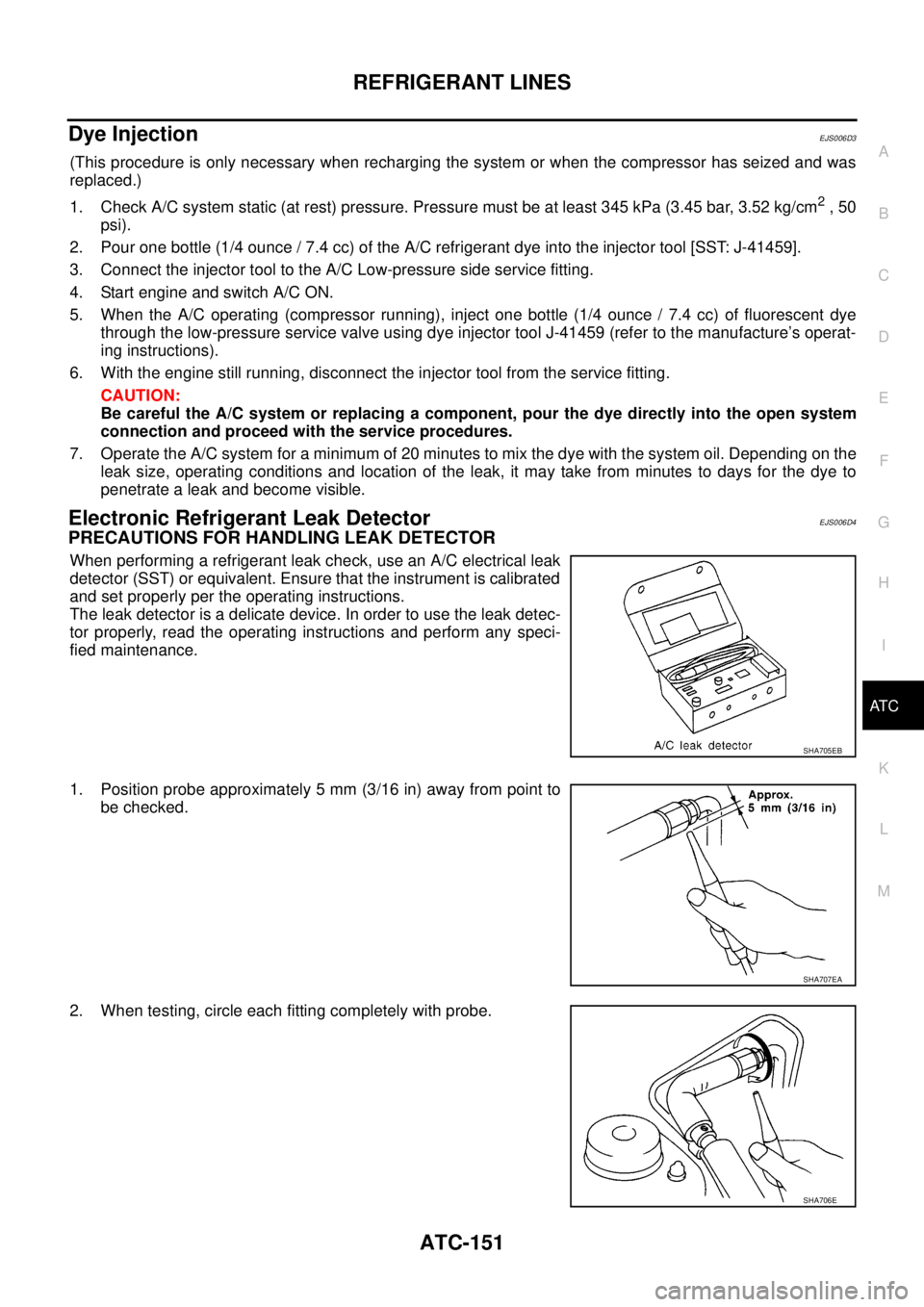
When performing a refrigerant leak check, use an A/C electrical leak
detector (SST) or equivalent. Ensure that the instrument is calibrated
and set properly per the operating instructions.
The leak detector is a delicate device. In order to use the leak detec-
tor properly, read the operating instructions and perform any speci-
fied maintenance.
1. Position probe approximately 5 mm (3/16 in) away from point to
be checked.
2. When testing, circle each fitting completely with probe.
SHA705EB
SHA707EA
SHA706E
Page 809 of 3171
VACUUM LINES
BR-23
C
D
E
G
H
I
J
K
L
MA
B
BR
Removal and InstallationEFS005SW
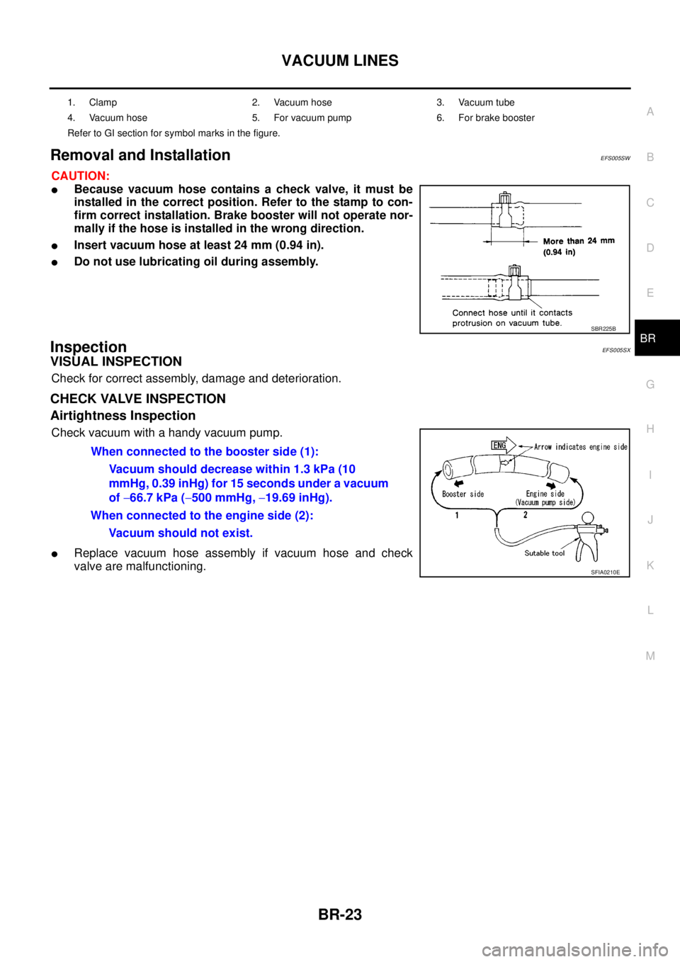
CAUTION:
lBecause vacuum hose contains a check valve, it must be
installed in the correct position. Refer to the stamp to con-
firm correct installation. Brake booster will not operate nor-
mally if the hose is installed in the wrong direction.
lInsert vacuum hose at least 24 mm (0.94 in).
lDo not use lubricating oil during assembly.
InspectionEFS005SX
VISUAL INSPECTION
Check for correct assembly, damage and deterioration.
CHECK VALVE INSPECTION
Airtightness Inspection
Check vacuum with a handy vacuum pump.
lReplace vacuum hose assembly if vacuum hose and check
valve are malfunctioning.
1. Clamp 2. Vacuum hose 3. Vacuum tube
4. Vacuum hose 5. For vacuum pump 6. For brake booster
Refer to GI section for symbol marks in the figure.
SBR225B
When connected to the booster side (1):
Vacuum should decrease within 1.3 kPa (10
mmHg, 0.39 inHg) for 15 seconds under a vacuum
of-66.7 kPa (-500 mmHg,-19.69 inHg).
When connected to the engine side (2):
Vacuum should not exist.
SFIA0210E
Page 812 of 3171
BR-26
FRONT DISC BRAKE
Removal and Installation of Brake Caliper Assembly
EFS005T1
REMOVAL
1. Remove tyre from vehicle.
2. Fasten disc rotor using wheel nut.
CAUTION:
Align the matching marks of disc rotor and wheel hub, which were marked at the time of removal
when reusing disc rotor.
3. Drain brake fluid. Refer toBR-10, "
Drain and Refill".
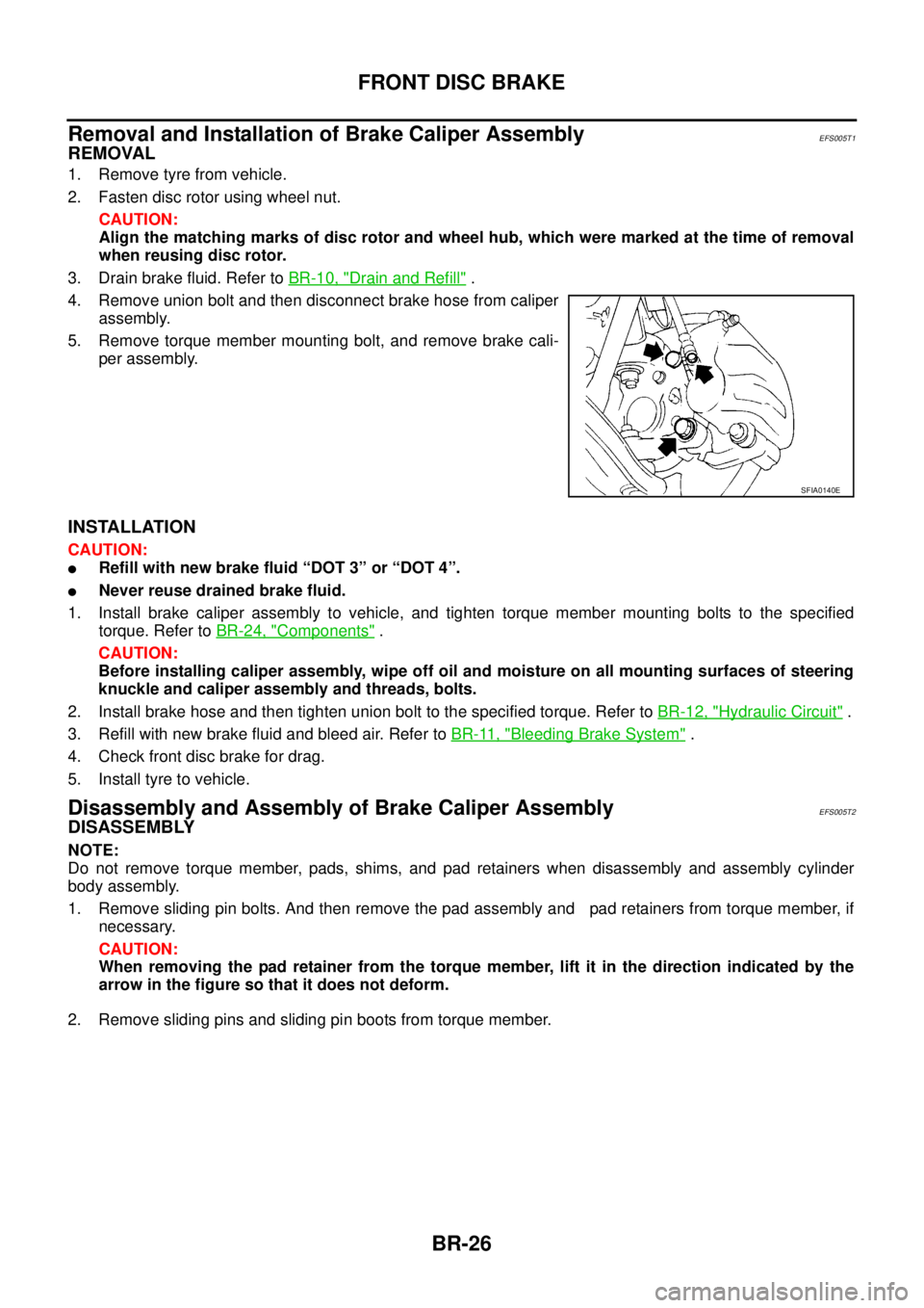
4. Remove union bolt and then disconnect brake hose from caliper
assembly.
5. Remove torque member mounting bolt, and remove brake cali-
per assembly.
INSTALLATION
CAUTION:
lRefill with new brake fluid “DOT 3” or “DOT 4”.
lNever reuse drained brake fluid.
1. Install brake caliper assembly to vehicle, and tighten torque member mounting bolts to the specified
torque. Refer toBR-24, "
Components".
CAUTION:
Before installing caliper assembly, wipe off oil and moisture on all mounting surfaces of steering
knuckle and caliper assembly and threads, bolts.
2. Install brake hose and then tighten union bolt to the specified torque. Refer toBR-12, "
Hydraulic Circuit".
3. Refill with new brake fluid and bleed air. Refer toBR-11, "
Bleeding Brake System".
4. Check front disc brake for drag.
5. Install tyre to vehicle.
Disassembly and Assembly of Brake Caliper AssemblyEFS005T2
DISASSEMBLY
NOTE:
Do not remove torque member, pads, shims, and pad retainers when disassembly and assembly cylinder
body assembly.
1. Remove sliding pin bolts. And then remove the pad assembly and pad retainers from torque member, if
necessary.
CAUTION:
When removing the pad retainer from the torque member, lift it in the direction indicated by the
arrow in the figure so that it does not deform.
2. Remove sliding pins and sliding pin boots from torque member.
SFIA0140E
Page 813 of 3171
FRONT DISC BRAKE
BR-27
C
D
E
G
H
I
J
K
L
MA
B
BR
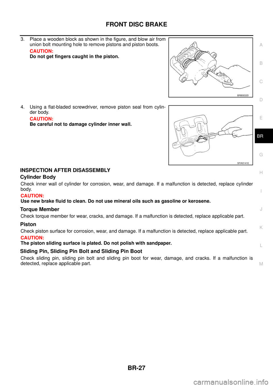
3. Place a wooden block as shown in the figure, and blow air from
union bolt mounting hole to remove pistons and piston boots.
CAUTION:
Do not get fingers caught in the piston.
4. Using a flat-bladed screwdriver, remove piston seal from cylin-
der body.
CAUTION:
Be careful not to damage cylinder inner wall.
INSPECTION AFTER DISASSEMBLY
Cylinder Body
Check inner wall of cylinder for corrosion, wear, and damage. If a malfunction is detected, replace cylinder
body.
CAUTION:
Use new brake fluid to clean. Do not use mineral oils such as gasoline or kerosene.
Torque Member
Check torque member for wear, cracks, and damage. If a malfunction is detected, replace applicable part.
Piston
Check piston surface for corrosion, wear, and damage. If a malfunction is detected, replace applicable part.
CAUTION:
The piston sliding surface is plated. Do not polish with sandpaper.
Sliding Pin, Sliding Pin Bolt and Sliding Pin Boot
Check sliding pin, sliding pin bolt and sliding pin boot for wear, damage, and cracks. If a malfunction is
detected, replace applicable part.
BRB0032D
SFIA0141E
Page 825 of 3171
![NISSAN NAVARA 2005 Repair Workshop Manual PRECAUTIONS
BRC-3
[ABS]
C
D
E
G
H
I
J
K
L
MA
B
BRC
[ABS]PRECAUTIONSPFP:00001
Precautions for Supplemental Restraint System (SRS) “AIR BAG” and “SEAT
BELT PRE-TENSIONER”
EFS006DM
The Supplement NISSAN NAVARA 2005 Repair Workshop Manual PRECAUTIONS
BRC-3
[ABS]
C
D
E
G
H
I
J
K
L
MA
B
BRC
[ABS]PRECAUTIONSPFP:00001
Precautions for Supplemental Restraint System (SRS) “AIR BAG” and “SEAT
BELT PRE-TENSIONER”
EFS006DM
The Supplement](/manual-img/5/57362/w960_57362-824.png)
PRECAUTIONS
BRC-3
[ABS]
C
D
E
G
H
I
J
K
L
MA
B
BRC
[ABS]PRECAUTIONSPFP:00001
Precautions for Supplemental Restraint System (SRS) “AIR BAG” and “SEAT
BELT PRE-TENSIONER”
EFS006DM
The Supplemental Restraint System such as “AIR BAG” and “SEAT BELT PRE-TENSIONER”, used along
with a front seat belt, helps to reduce the risk or severity of injury to the driver and front passenger for certain
types of collision. Information necessary to service the system safely is included in the SRS and SB section of
this Service Manual.
WARNING:
lTo avoid rendering the SRS inoperative, which could increase the risk of personal injury or death
in the event of a collision which would result in air bag inflation, all maintenance must be per-
formed by an authorized NISSAN/INFINITI dealer.
lImproper maintenance, including incorrect removal and installation of the SRS, can lead to per-
sonal injury caused by unintentional activation of the system. For removal of Spiral Cable and Air
Bag Module, see the SRS section.
lDo not use electrical test equipment on any circuit related to the SRS unless instructed to in this
Service Manual. SRS wiring harnesses can be identified by yellow and/or orange harnesses or
harness connectors.
Precautions for Brake SystemEFS005TG
lRecommended fluid is brake fluid “DOT 3” or “DOT 4”.
lNever reuse drained brake fluid.
lBe careful not to splash brake fluid on painted areas.If brake fluid is splashed, wipe it off and flush area
with water immediately.
lNever use mineral oils such as gasoline or kerosene. They will ruin rubber parts of the hydraulic system.
lUse flare nut wrench when removing flare nuts, and use a flare
nut torque wrench when tighten flare nuts.
lBrake system is an important safety part.If a brake fluid leak is
detected, always disassemble the affected part.If a malfunction
is detected, replace part with new one.
lBefore working, turn ignition switch OFF and disconnect con-
nector of ABS actuator and electric unit (control unit) or the bat-
tery cables.
lWhen installing brake tube and hose, be sure to torque.
WARNING:
Clean brake pads and shoes with a waster cloth, then wipe with
a dust collector.
Precautions for Brake ControlEFS005TH
lJust after starting vehicle after ignition switch ON, brake pedal may vibrate or motor operating noise may
be heard from engine room. This is a normal status of operation check.
lStopping distance may be longer than that of vehicles without ABS when vehicle drives on rough, gravel,
or snow-covered (fresh, deep snow) roads.
lWhen an error is indicated by ABS or another warning lamp, collect all necessary information from cus-
tomer (what symptoms are present under what conditions) and check for simple causes before starting
diagnostic servicing. Besides electrical system inspection, check brake booster operation, brake fluid
level, and fluid leaks.
lIf tyre size and type are used in an improper combination, or brake pads are not Genuine NISSAN parts,
stopping distance or steering stability may deteriorate.
lIf there is a radio, antenna, or antenna lead-in wire (including wiring) near control module, ABS function
may have a malfunction or error.
lIf aftermarket parts (car stereo, CD player, etc.) have been installed, check for incidents such as harness
pinches, open circuits, and improper wiring.
SBR820BA
Page 897 of 3171
RADIATOR
CO-13
C
D
E
F
G
H
I
J
K
L
MA
CO
INSPECTION AFTER REMOVAL
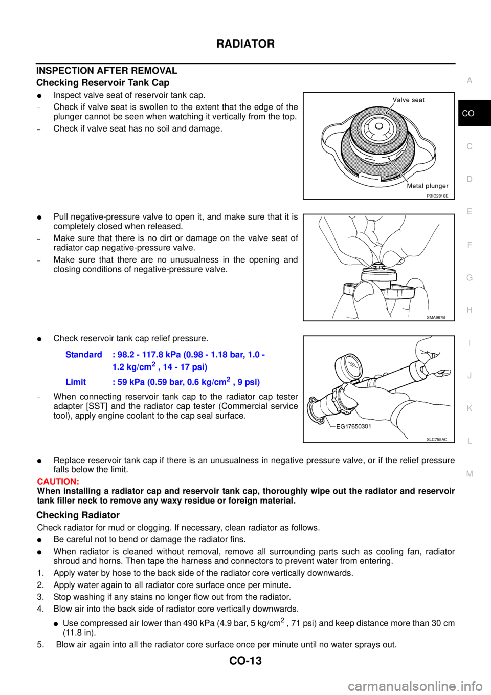
Checking Reservoir Tank Cap
lInspect valve seat of reservoir tank cap.
–Check if valve seat is swollen to the extent that the edge of the
plunger cannot be seen when watching it vertically from the top.
–Check if valve seat has no soil and damage.
lPull negative-pressure valve to open it, and make sure that it is
completely closed when released.
–Make sure that there is no dirt or damage on the valve seat of
radiator cap negative-pressure valve.
–Make sure that there are no unusualness in the opening and
closing conditions of negative-pressure valve.
lCheck reservoir tank cap relief pressure.
–When connecting reservoir tank cap to the radiator cap tester
adapter [SST] and the radiator cap tester (Commercial service
tool), apply engine coolant to the cap seal surface.
lReplace reservoir tank cap if there is an unusualness in negative pressure valve, or if the relief pressure
falls below the limit.
CAUTION:
When installing a radiator cap and reservoir tank cap, thoroughly wipe out the radiator and reservoir
tank filler neck to remove any waxy residue or foreign material.
Checking Radiator
Check radiator for mud or clogging. If necessary, clean radiator as follows.
lBe careful not to bend or damage the radiator fins.
lWhen radiator is cleaned without removal, remove all surrounding parts such as cooling fan, radiator
shroud and horns. Then tape the harness and connectors to prevent water from entering.
1. Apply water by hose to the back side of the radiator core vertically downwards.
2. Apply water again to all radiator core surface once per minute.
3. Stop washing if any stains no longer flow out from the radiator.
4. Blow air into the back side of radiator core vertically downwards.
lUse compressed air lower than 490 kPa (4.9 bar, 5 kg/cm2, 71 psi) and keep distance more than 30 cm
(11.8 in).
5. Blow air again into all the radiator core surface once per minute until no water sprays out.
PBIC2816E
SMA967B
Standard : 98.2 - 117.8 kPa (0.98 - 1.18 bar, 1.0 -
1.2 kg/cm
2,14-17psi)
Limit : 59 kPa (0.59 bar, 0.6 kg/cm
2,9psi)
SLC755AC
Page 903 of 3171
COOLING FAN
CO-19
C
D
E
F
G
H
I
J
K
L
MA
CO
COOLING FANPFP:21140
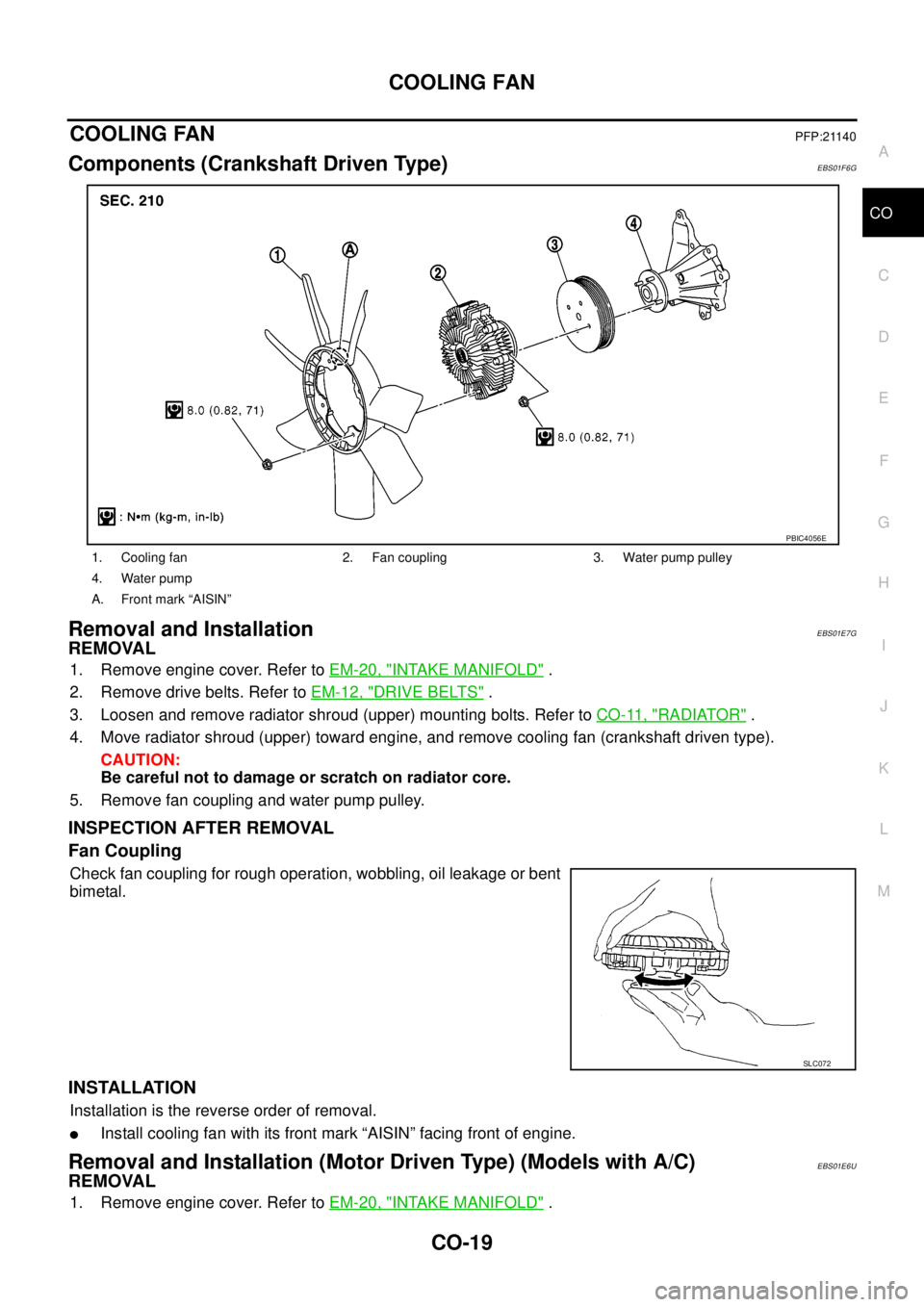
Components (Crankshaft Driven Type)EBS01F6G
Removal and InstallationEBS01E7G
REMOVAL
1. Remove engine cover. Refer toEM-20, "INTAKE MANIFOLD".
2. Remove drive belts. Refer toEM-12, "
DRIVE BELTS".
3. Loosen and remove radiator shroud (upper) mounting bolts. Refer toCO-11, "
RADIATOR".
4. Move radiator shroud (upper) toward engine, and remove cooling fan (crankshaft driven type).
CAUTION:
Be careful not to damage or scratch on radiator core.
5. Remove fan coupling and water pump pulley.
INSPECTION AFTER REMOVAL
Fan Coupling
Check fan coupling for rough operation, wobbling, oil leakage or bent
bimetal.
INSTALLATION
Installation is the reverse order of removal.
lInstall cooling fan with its front mark “AISIN” facing front of engine.
Removal and Installation (Motor Driven Type) (Models with A/C)EBS01E6U
REMOVAL
1. Remove engine cover. Refer toEM-20, "INTAKE MANIFOLD".
1. Cooling fan 2. Fan coupling 3. Water pump pulley
4. Water pump
A. Front mark “AISIN”
PBIC4056E
SLC072
Page 908 of 3171
CO-24
THERMOSTAT AND WATER PIPING
Removal and Installation
EBS01E6X
WARNING:
Do not remove radiator cap and/or reservoir tank cap when engine is hot. Serious burns could occur
from high pressure engine coolant escaping from radiator and/or reservoir tank.
REMOVAL
1. Remove front engine undercover and middle engine undercover. Refer toEI-15, "FRONT BUMPER".
2. Drain engine coolant from radiator drain plug at the bottom of radiator, and from water drain plug at the
side of cylinder block. Refer toCO-7, "
Changing Engine Coolant"andEM-110, "CYLINDER BLOCK".
CAUTION:
Perform this step when engine is cold.
3. Remove engine cover. Refer toEM-20, "
INTAKE MANIFOLD".
4. Disconnect radiator hoses (upper and lower) from engine side. Refer toCO-11, "
RADIATOR".
5. Remove air inlet pipe and air duct between air cleaner case and turbocharger. Refer toEM-15, "
AIR
CLEANER AND AIR DUCT"andEM-28, "TURBO CHARGER".
6. Remove water outlet, water inlet and thermostat.
7. Remove thermostat housing.
8. Disconnect heater return hose and water hoses at heater return pipe side, and remove heater return pipe.
9. Remove oil level gauge guide mounting bolt, vacuum hoses (to turbocharger boost control solenoid valve)
and spill hose. Refer toEM-36, "
OIL PAN AND OIL STRAINER",EM-20, "INTAKE MANIFOLD"andEM-
44, "INJECTION TUBE AND FUEL INJECTOR".
10. Disconnect water hoses (to EGR cooler) (A/T models), vacuum hoses and heater feed hose at heater
feed pipe side, and remove heater feed pipe. Refer toEM-20, "
INTAKE MANIFOLD".
INSPECTION AFTER REMOVAL
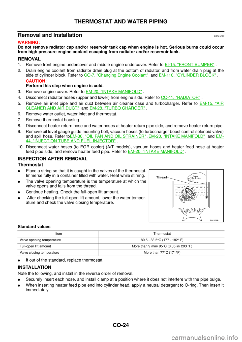
Thermostat
lPlace a string so that it is caught in the valves of the thermostat.
Immerse fully in a container filled with water. Heat while stirring.
lThe valve opening temperature is the temperature at which the
valve opens and falls from the thread.
lContinue heating. Check the full-open lift amount.
lAfter checking the full-open lift amount, lower the water temper-
ature and check the valve closing temperature.
Standard values
lIf out of the standard, replace thermostat.
INSTALLATION
Note the following, and install in the reverse order of removal.
lSecurely insert each hose, and install clamp at a position where it does not interfere with the pipe bulge.
lWhen inserting heater feed pipe end into cylinder head, apply a neutral detergent to O-ring. Then insert it
immediately.
SLC252B
Item Thermostat
Valve opening temperature 80.5 - 83.5°C (177 - 182°F)
Full-open lift amount More than 9 mm/ 95°C (0.35 in/ 203°F)
Valve closing temperature More than 77°C(171°F)