Page 245 of 3171

ON-VEHICLE SERVICE
AT-237
D
E
F
G
H
I
J
K
L
MA
B
AT
Rear Oil SealECS00GVM
REMOVAL AND INSTALLATION
Removal
1. Remove rear propeller shaft. Refer toPR-8, "Removal and
Installation".
2. Remove transfer from A/T assembly (4WD models). Refer to
T F - 111 , "
Removal and Installation".
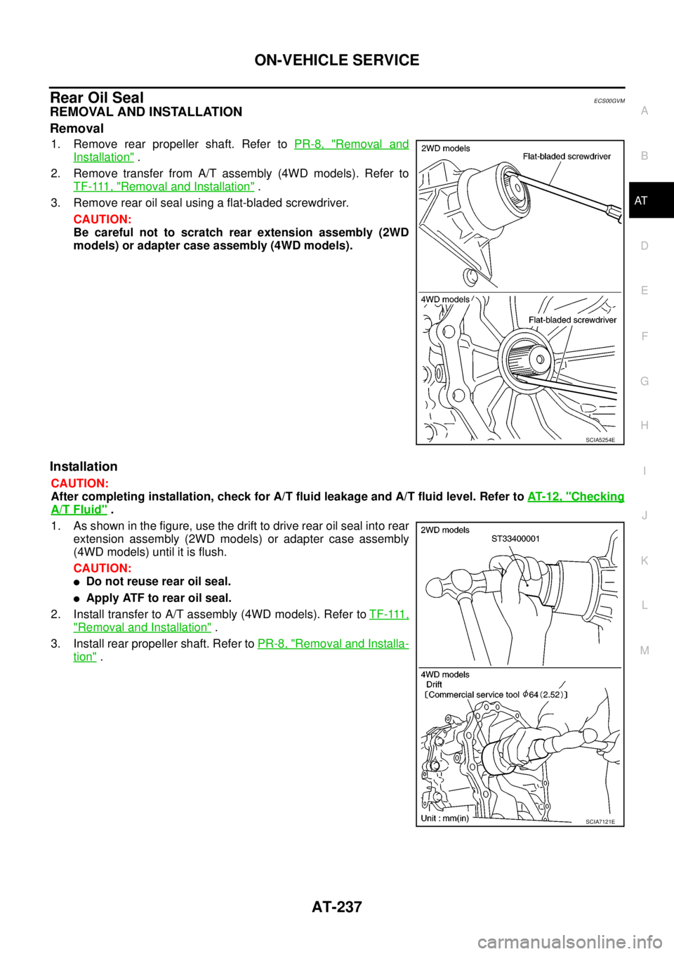
3. Remove rear oil seal using a flat-bladed screwdriver.
CAUTION:
Be careful not to scratch rear extension assembly (2WD
models) or adapter case assembly (4WD models).
Installation
CAUTION:
After completing installation, check for A/T fluid leakage and A/T fluid level. Refer toAT- 1 2 , "
Checking
A/T Fluid".
1. As shown in the figure, use the drift to drive rear oil seal into rear
extension assembly (2WD models) or adapter case assembly
(4WD models) until it is flush.
CAUTION:
lDo not reuse rear oil seal.
lApply ATF to rear oil seal.
2. Install transfer to A/T assembly (4WD models). Refer toT F - 111 ,
"Removal and Installation".
3. Install rear propeller shaft. Refer toPR-8, "
Removal and Installa-
tion".
SCIA5254E
SCIA7121E
Page 247 of 3171

ON-VEHICLE SERVICE
AT-239
D
E
F
G
H
I
J
K
L
MA
B
AT
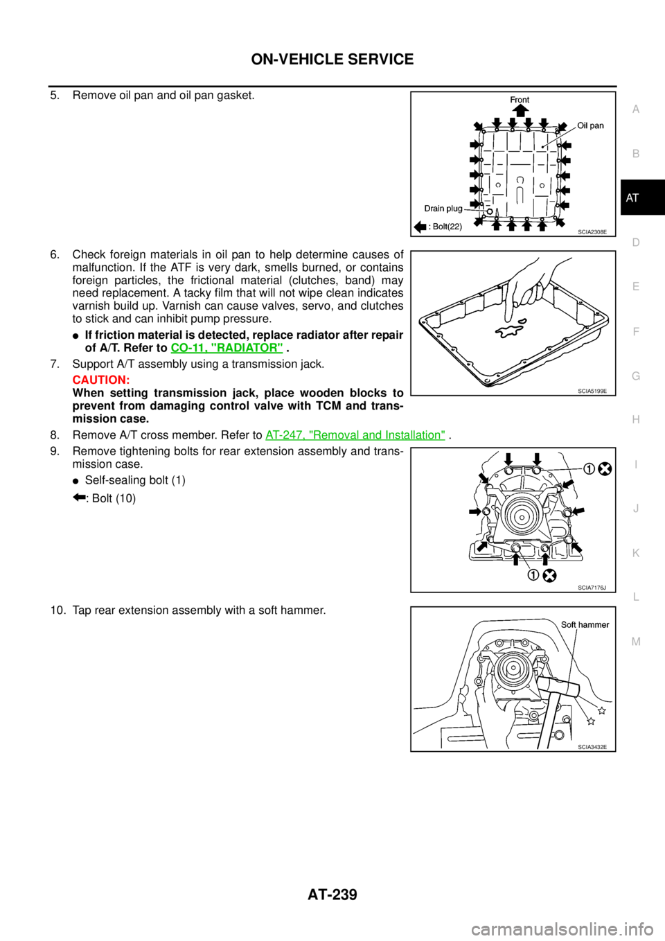
5. Remove oil pan and oil pan gasket.
6. Check foreign materials in oil pan to help determine causes of
malfunction. If the ATF is very dark, smells burned, or contains
foreign particles, the frictional material (clutches, band) may
need replacement. A tacky film that will not wipe clean indicates
varnish build up. Varnish can cause valves, servo, and clutches
to stick and can inhibit pump pressure.
lIf friction material is detected, replace radiator after repair
of A/T. Refer toCO-11, "
RADIATOR".
7. Support A/T assembly using a transmission jack.
CAUTION:
When setting transmission jack, place wooden blocks to
prevent from damaging control valve with TCM and trans-
mission case.
8. Remove A/T cross member. Refer toAT- 2 4 7 , "
Removal and Installation".
9. Remove tightening bolts for rear extension assembly and trans-
mission case.
lSelf-sealing bolt (1)
: Bolt (10)
10. Tap rear extension assembly with a soft hammer.
SCIA2308E
SCIA5199E
SCIA7176J
SCIA3432E
Page 249 of 3171

ON-VEHICLE SERVICE
AT-241
D
E
F
G
H
I
J
K
L
MA
B
AT
Installation
CAUTION:
After completing installation, check A/T fluid leakage, A/T fluid level and A/T position. Refer toAT- 1 2 ,
"Checking A/T Fluid",AT- 2 11 , "Checking of A/T Position".
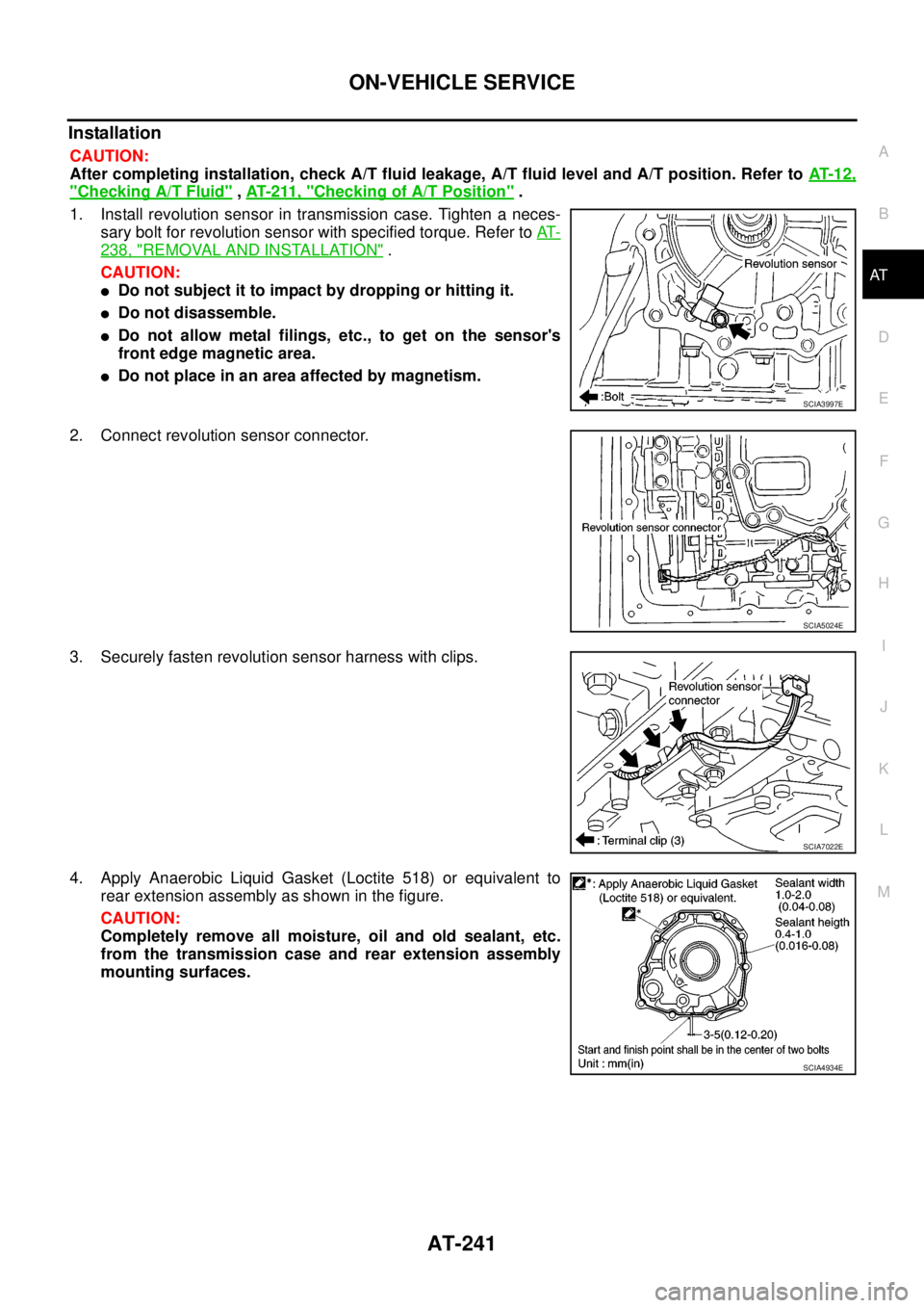
1. Install revolution sensor in transmission case. Tighten a neces-
sary bolt for revolution sensor with specified torque. Refer toAT-
238, "REMOVAL AND INSTALLATION".
CAUTION:
lDo not subject it to impact by dropping or hitting it.
lDo not disassemble.
lDo not allow metal filings, etc., to get on the sensor's
front edge magnetic area.
lDo not place in an area affected by magnetism.
2. Connect revolution sensor connector.
3. Securely fasten revolution sensor harness with clips.
4. Apply Anaerobic Liquid Gasket (Loctite 518) or equivalent to
rear extension assembly as shown in the figure.
CAUTION:
Completely remove all moisture, oil and old sealant, etc.
from the transmission case and rear extension assembly
mounting surfaces.
SCIA3997E
SCIA5024E
SCIA7022E
SCIA4934E
Page 277 of 3171
DISASSEMBLY
AT-269
D
E
F
G
H
I
J
K
L
MA
B
AT
28. Remove oil pan and oil pan gasket.
29. Check foreign materials in oil pan to help determine causes of
malfunction. If the A/T fluid is very dark, smells burned, or con-
tains foreign particles, the frictional material (clutches, band)
may need replacement. A tacky film that will not wipe clean indi-
cates varnish build up. Varnish can cause valves, servo, and
clutches to stick and can inhibit pump pressure.
lIf friction material is detected, replace radiator after repair
of A/T. Refer toCO-11, "
RADIATOR".
30. Remove magnets from oil pan.
31. Disconnect A/T fluid temperature sensor 2 connector.
CAUTION:
Be careful not to damage connector.
32. Straighten terminal clips to free terminal cord assembly and A/T
fluid temperature sensor 2 harness.
SCIA2308E
SCIA5199E
SCIA5200E
SCIA5023E
SCIA5446E
Page 283 of 3171
DISASSEMBLY
AT-275
D
E
F
G
H
I
J
K
L
MA
B
AT
49. Remove revolution sensor from transmission case.
CAUTION:
lDo not subject it to impact by dropping or hitting it.
lDo not disassemble.
lDo not allow metal filings, etc. to get on sensor's front
edge magnetic area.
lDo not place in an area affected by magnetism.
50. Remove reverse brake snap ring (fixing plate) using 2 flat-
bladed screwdrivers.
NOTE:
Press out snap ring from transmission case oil pan side
gap using a flat-bladed screwdriver, and remove it using a
another screwdriver.
51. Remove reverse brake retaining plate from transmission case.
lCheck facing for burns, cracks or damage. If necessary,
replace the plate.
52. Remove N-spring from transmission case.
53. Remove reverse brake drive plates, driven plates and dish plate
from transmission case.
lCheck facing for burns, cracks or damage. If necessary,
replace the plate.
SCIA2320E
SCIA5032E
SCIA5214E
SCIA2322E
Page 293 of 3171
REPAIR FOR COMPONENT PARTS
AT-285
D
E
F
G
H
I
J
K
L
MA
B
AT
INSPECTION
3rd One-way Clutch
lCheck frictional surface for wear or damage.
CAUTION:
If necessary, replace 3rd one-way clutch.
Front Sun Gear Snap Ring
lCheck for deformation, fatigue or damage.
CAUTION:
If necessary, replace snap ring.
Front Sun Gear
lCheck for deformation, fatigue or damage.
CAUTION:
If necessary, replace front sun gear.
ASSEMBLY
1. Install 3rd one-way clutch in front sun gear.
2. Install snap ring in front sun gear using a flat-bladed screwdriver.
3. Check operation of 3rd one-way clutch.
a. Hold oil pump assembly and turn front sun gear.
b. Check 3rd one-way clutch for correct locking and unlocking
directions.
CAUTION:
If not as shown in figure, check installation direction of 3rd
one-way clutch.
S C I A 3 111 E
SCIA3110E
SCIA3131E
Page 418 of 3171

ATC-84
TROUBLE DIAGNOSIS
6.CHECK VARIABLE BLOWER CONTROL POWER SUPPLY CIRCUIT FOR OPEN
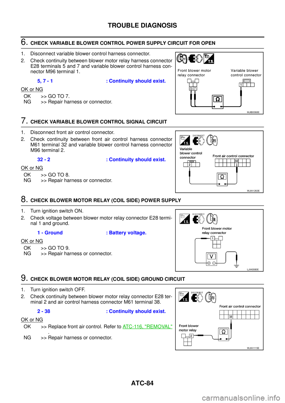
1. Disconnect variable blower control harness connector.
2. Check continuity between blower motor relay harness connector
E28 terminals 5 and 7 and variable blower control harness con-
nector M96 terminal 1.
OK or NG
OK >> GO TO 7.
NG >> Repair harness or connector.
7.CHECK VARIABLE BLOWER CONTROL SIGNAL CIRCUIT
1. Disconnect front air control connector.
2. Check continuity between front air control harness connector
M61 terminal 32 and variable blower control harness connector
M96 terminal 2.
OK or NG
OK >> GO TO 8.
NG >> Repair harness or connector.
8.CHECK BLOWER MOTOR RELAY (COIL SIDE) POWER SUPPLY
1. Turn ignition switch ON.
2. Check voltage between blower motor relay connector E28 termi-
nal 1 and ground.
OK or NG
OK >> GO TO 9.
NG >> Repair harness or connector.
9.CHECK BLOWER MOTOR RELAY (COIL SIDE) GROUND CIRCUIT
1. Turn ignition switch OFF.
2. Check continuity between blower motor relay connector E28 ter-
minal 2 and air control harness connector M61 terminal 38.
OK or NG
OK >> Replace front air control. Refer toAT C - 11 6 , "REMOVAL"
.
NG >> Repair harness or connector.5, 7 - 1 : Continuity should exist.
MJIB0068E
32 - 2 : Continuity should exist.
WJIA1263E
1 - Ground : Battery voltage.
LJIA0080E
2 - 38 : Continuity should exist.
WJIA1115E
Page 420 of 3171
ATC-86
TROUBLE DIAGNOSIS
COMPONENT INSPECTION
Blower Motor Relay
Check continuity between terminals by supplying 12 volts and
ground to coil side terminals of relay.
Blower Motor
Confirm smooth rotation of the blower motor.
lEnsure that there are no foreign particles inside the blower unit.
lApply 12 volts to terminal + and ground to terminal - and verify
that the motor operates freely and quietly.
LJIA0068E
WJIA1265E